alternator DODGE NEON 1999 Service Repair Manual
[x] Cancel search | Manufacturer: DODGE, Model Year: 1999, Model line: NEON, Model: DODGE NEON 1999Pages: 1200, PDF Size: 35.29 MB
Page 867 of 1200

CRANKSHAFT POSITION SENSORÐPCM INPUT
The PCM determines what cylinder to fire from the
crankshaft position sensor input and the camshaft
position sensor input. The second crankshaft counter-
weight has two sets of four timing reference notches
including a 60 degree signature notch (Fig. 7). From
the crankshaft position sensor input the PCM deter-
mines engine speed and crankshaft angle (position).
The notches generate pulses from high to low in
the crankshaft position sensor output voltage. When
a metal portion of the counterweight aligns with the
crankshaft position sensor, the sensor output voltage
goes low (less than 0.5 volts). When a notch aligns
with the sensor, voltage goes high (5.0 volts). As a
group of notches pass under the sensor, the outputvoltage switches from low (metal) to high (notch)
then back to low.
If available, an oscilloscope can display the square
wave patterns of each voltage pulses. From the width
of the output voltage pulses, the PCM calculates
engine speed. The width of the pulses represent the
amount of time the output voltage stays high before
switching back to low. The period of time the sensor
output voltage stays high before switching back to
low is referred to as pulse width. The faster the
engine is operating, the smaller the pulse width on
the oscilloscope.
By counting the pulses and referencing the pulse
from the 60 degree signature notch, the PCM calcu-
lates crankshaft angle (position). In each group of
timing reference notches, the first notch represents
69 degrees before top dead center (BTDC). The sec-
ond notch represents 49 degrees BTDC. The third
notch represents 29 degrees. The last notch in each
set represents 9 degrees before top dead center
(TDC).
The timing reference notches are machined at 20É
increments. From the voltage pulse width the PCM
tells the difference between the timing reference
notches and the 60 degree signature notch. The 60
degree signature notch produces a longer pulse width
than the smaller timing reference notches. If the
camshaft position sensor input switches from high to
low when the 60 degree signature notch passes under
the crankshaft position sensor, the PCM knows cylin-
der number one is the next cylinder at TDC.
The crankshaft position sensor mounts to the
engine block behind the alternator, just above the oil
filter (Fig. 8).
ENGINE COOLANT TEMPERATURE SENSORÐPCM
INPUT
The combination coolant temperature sensor has
two elements. One element supplies coolant temper-
ature signal to the PCM. The other element supplies
coolant temperature signal to the instrument panel
gauge cluster. The PCM determines engine coolant
temperature from the coolant temperature sensor.
As coolant temperature varies the coolant temper-
ature sensors resistance changes resulting in a differ-
ent input voltage to the PCM and the instrument
panel gauge cluster.
When the engine is cold, the PCM will provide
slightly richer air- fuel mixtures and higher idle
speeds until normal operating temperatures are
reached.
SOHC
The coolant sensor threads into the rear of the cyl-
inder head, next to the camshaft position sensor (Fig.
9). New sensors have sealant applied to the threads.
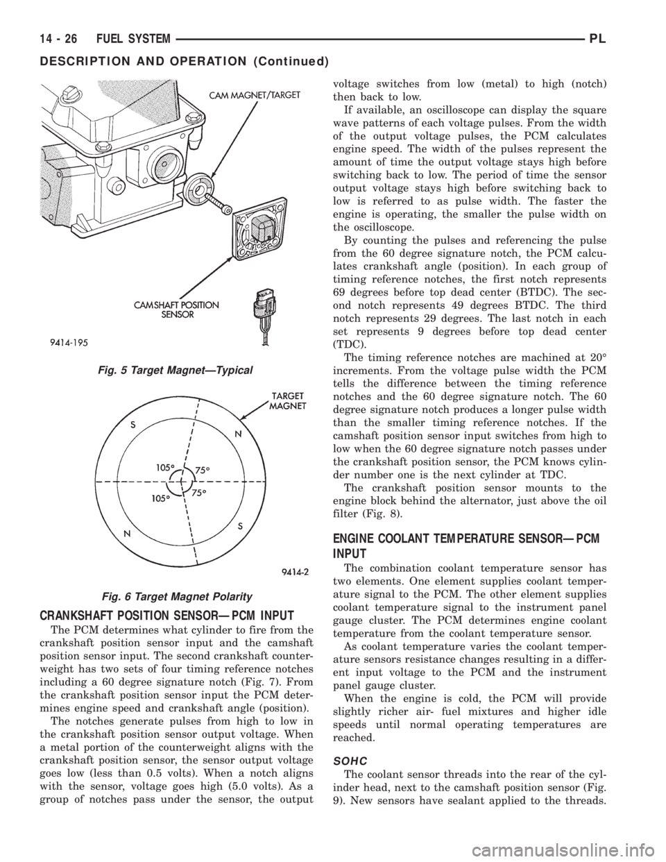
Fig. 5 Target MagnetÐTypical
Fig. 6 Target Magnet Polarity
14 - 26 FUEL SYSTEMPL
DESCRIPTION AND OPERATION (Continued)
Page 1152 of 1200

(4) Remove two resistor block retaining screws.
The screw threads attaching the resistor block are
not full length. It is necessary to gently pry out the
resistor block while turning the screws counterclock-
wise enabling the threads to engages.
(5) Remove resistor block from vehicle.
INSTALLATION
For installation, reverse the above procedures.
BLOWER MOTOR WHEEL
The blower motor wheel is only serviced with the
blower motor. The wheel and the motor are balanced
as an assembly. If the blower motor wheel requires
replacement, the blower motor must also be replaced.
Refer to blower motor for replacement procedure.
COMPRESSOR
CAUTION: Add only new lubricant when system
requires additional lubricant. Do not use old
reclaimed lubricant.
REMOVAL
The A/C compressor may be unbolted and reposi-
tioned without discharging the refrigerant system.
Discharging is not necessary if removing the com-
pressor clutch/coil assembly, engine, cylinder head, or
alternator.
WARNING: REFRIGERANT PRESSURES REMAIN
HIGH EVEN THOUGH THE ENGINE MAY BE
TURNED OFF. DO NOT TWIST OR KINK THE
REFRIGERANT LINES WHEN REMOVING A FULLY
CHARGED COMPRESSOR. SAFETY GLASSES
MUST BE WORN.
(1) Disconnect battery negative cable.
(2) Loosen and remove drive belts, refer to Group
7, Engine Cooling.
(3) Using a R-134a refrigerant recovery machine,
remove the refrigerant from A/C system. If the com-
pressor is being replaced.
(4) Disconnect compressor clutch wire lead.
(5) Remove refrigerant lines from compressor, if
necessary.
(6) If system is left open place plug/cap over open
lines.
(7) Remove compressor attaching bolt.
(8) Remove compressor. If refrigerant lines were
not removed, lift compressor/clutch assembly and tie
it to a suitable component.
INSTALLATION
For installation, reverse the above procedures.
COMPRESSOR CLUTCH/COIL ASSEMBLY
Compressor assembly must be removed from mount-
ing. Although, refrigerant discharge is not necessary.
REMOVAL
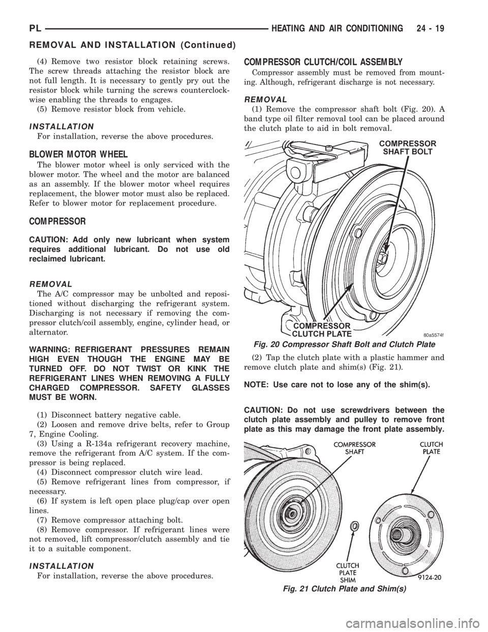
(1) Remove the compressor shaft bolt (Fig. 20). A
band type oil filter removal tool can be placed around
the clutch plate to aid in bolt removal.
(2) Tap the clutch plate with a plastic hammer and
remove clutch plate and shim(s) (Fig. 21).
NOTE: Use care not to lose any of the shim(s).
CAUTION: Do not use screwdrivers between the
clutch plate assembly and pulley to remove front
plate as this may damage the front plate assembly.
Fig. 20 Compressor Shaft Bolt and Clutch Plate
Fig. 21 Clutch Plate and Shim(s)
PLHEATING AND AIR CONDITIONING 24 - 19
REMOVAL AND INSTALLATION (Continued)