oil level DODGE NEON 1999 Service Repair Manual
[x] Cancel search | Manufacturer: DODGE, Model Year: 1999, Model line: NEON, Model: DODGE NEON 1999Pages: 1200, PDF Size: 35.29 MB
Page 4 of 1200
MAINTENANCE SCHEDULES
INDEX
page page
GENERAL INFORMATION
INTRODUCTION......................... 3
SCHEDULE ± A.......................... 3SCHEDULE ± B.......................... 4
UNSCHEDULED INSPECTION............... 3
GENERAL INFORMATION
INTRODUCTION
Service and maintenance procedures for compo-
nents and systems listed in Schedule ± A or B can be
found by using the Group Tab Locator index at the
front of this manual. If it is not clear which group
contains the information needed, refer to the index at
the back of this manual.
There are two maintenance schedules that show
proper service based on the conditions that the vehi-
cle is subjected to. Use the schedule that best
describes these conditions.
Schedule ±A, lists maintenance recommended for
vehicles used for general transportation.
Schedule ±B, lists maintenance recommended for
vehicles used under the following conditions:
²Frequent short trip driving less than 5 miles (8
km)
²Frequent driving in dusty conditions
²Frequent trailer towing
²Extensive idling
²More than 50% of your driving is at sustained
high speeds during hot weather, above 90ÉF (32ÉC)
Where time and mileage are listed, follow the
interval that occurs first.
EMISSION CONTROL SYSTEM MAINTENANCE
The scheduled emission maintenance listed inbold
typeon the Maintenance Schedules, must be done at
the mileage specified to assure the continued proper
functioning of the emission control system. These,
and all other maintenance services included in this
manual, should be done to provide the best vehicle
performance and reliability. More frequent mainte-
nance may be needed for vehicles in severe operating
conditions such as dusty areas and very short trip
driving.
UNSCHEDULED INSPECTION
At Each Stop For Fuel
²Check engine oil level, add as required.
²Check windshield washer solvent and add if
required.
Once A Month
²Check tire pressure and look for unusual wear
or damage.
²Inspect battery, clean, and tighten terminals as
required.
²Check fluid levels of coolant reservoir, power
steering and automatic transmission and add as
required.
²Check all lights and all other electrical items for
correct operation.
At Each Oil Change
²Inspect exhaust system.
²Inspect brake hoses.
²Inspect the CV joints and front suspension com-
ponents.
²Rotate the tires at each oil change interval
shown on Schedule ± A (7,500 miles) or every other
interval shown on schedule ± B (6,000 miles).
²Check coolant level, hoses and clamps.
²Check the manual transaxle fluid level.
²If the mileage is less than 7,500 miles (12 000
km) yearly, replace the engine oil filter at each oil
change.
SCHEDULE ± A
7,500 Miles (12 000 km) or at 6 months
²Change engine oil.
15,000 Miles (24 000 km) or at 12 months
²Change engine oil.
²Replace engine oil filter.
²Adjust drive belt tension.
22,500 Miles (36 000 km) or at 18 months
²Change engine oil.
²Inspect the front brake pads and rear brake lin-
ings.
30,000 Miles (48 000 km) or at 24 months
²Change engine oil.
²Replace engine oil filter.
²Lubricate front suspension ball joints.
²Adjust drive belt tension.
PLLUBRICATION AND MAINTENANCE 0 - 3
Page 100 of 1200
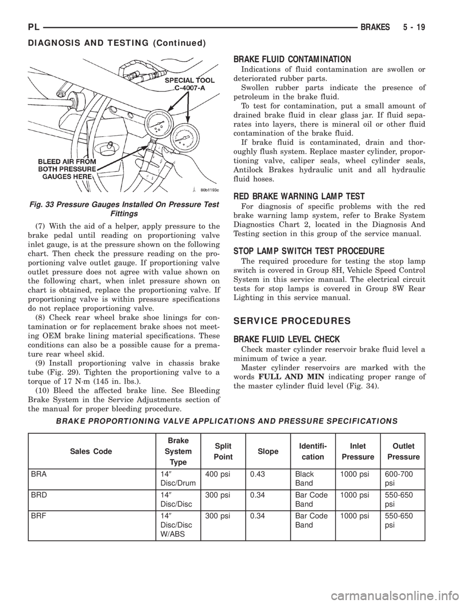
(7) With the aid of a helper, apply pressure to the
brake pedal until reading on proportioning valve
inlet gauge, is at the pressure shown on the following
chart. Then check the pressure reading on the pro-
portioning valve outlet gauge. If proportioning valve
outlet pressure does not agree with value shown on
the following chart, when inlet pressure shown on
chart is obtained, replace the proportioning valve. If
proportioning valve is within pressure specifications
do not replace proportioning valve.
(8) Check rear wheel brake shoe linings for con-
tamination or for replacement brake shoes not meet-
ing OEM brake lining material specifications. These
conditions can also be a possible cause for a prema-
ture rear wheel skid.
(9) Install proportioning valve in chassis brake
tube (Fig. 29). Tighten the proportioning valve to a
torque of 17 N´m (145 in. lbs.).
(10) Bleed the affected brake line. See Bleeding
Brake System in the Service Adjustments section of
the manual for proper bleeding procedure.
BRAKE FLUID CONTAMINATION
Indications of fluid contamination are swollen or
deteriorated rubber parts.
Swollen rubber parts indicate the presence of
petroleum in the brake fluid.
To test for contamination, put a small amount of
drained brake fluid in clear glass jar. If fluid sepa-
rates into layers, there is mineral oil or other fluid
contamination of the brake fluid.
If brake fluid is contaminated, drain and thor-
oughly flush system. Replace master cylinder, propor-
tioning valve, caliper seals, wheel cylinder seals,
Antilock Brakes hydraulic unit and all hydraulic
fluid hoses.
RED BRAKE WARNING LAMP TEST
For diagnosis of specific problems with the red
brake warning lamp system, refer to Brake System
Diagnostics Chart 2, located in the Diagnosis And
Testing section in this group of the service manual.
STOP LAMP SWITCH TEST PROCEDURE
The required procedure for testing the stop lamp
switch is covered in Group 8H, Vehicle Speed Control
System in this service manual. The electrical circuit
tests for stop lamps is covered in Group 8W Rear
Lighting in this service manual.
SERVICE PROCEDURES
BRAKE FLUID LEVEL CHECK
Check master cylinder reservoir brake fluid level a
minimum of twice a year.
Master cylinder reservoirs are marked with the
wordsFULL AND MINindicating proper range of
the master cylinder fluid level (Fig. 34).
Fig. 33 Pressure Gauges Installed On Pressure Test
Fittings
BRAKE PROPORTIONING VALVE APPLICATIONS AND PRESSURE SPECIFICATIONS
Sales CodeBrake
System
TypeSplit
PointSlopeIdentifi-
cationInlet
PressureOutlet
Pressure
BRA 149
Disc/Drum400 psi 0.43 Black
Band1000 psi 600-700
psi
BRD 149
Disc/Disc300 psi 0.34 Bar Code
Band1000 psi 550-650
psi
BRF 149
Disc/Disc
W/ABS300 psi 0.34 Bar Code
Band1000 psi 550-650
psi
PLBRAKES 5 - 19
DIAGNOSIS AND TESTING (Continued)
Page 161 of 1200
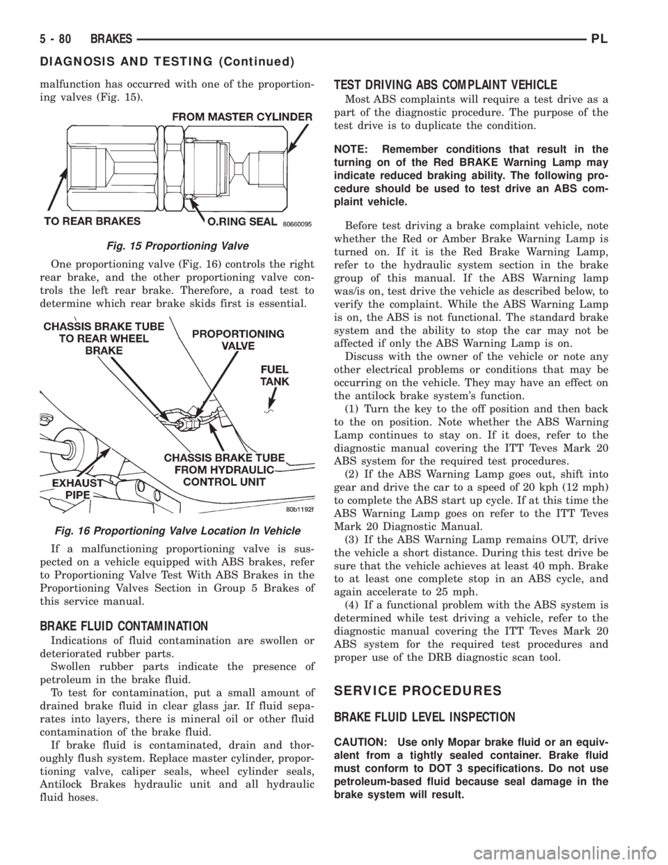
malfunction has occurred with one of the proportion-
ing valves (Fig. 15).
One proportioning valve (Fig. 16) controls the right
rear brake, and the other proportioning valve con-
trols the left rear brake. Therefore, a road test to
determine which rear brake skids first is essential.
If a malfunctioning proportioning valve is sus-
pected on a vehicle equipped with ABS brakes, refer
to Proportioning Valve Test With ABS Brakes in the
Proportioning Valves Section in Group 5 Brakes of
this service manual.
BRAKE FLUID CONTAMINATION
Indications of fluid contamination are swollen or
deteriorated rubber parts.
Swollen rubber parts indicate the presence of
petroleum in the brake fluid.
To test for contamination, put a small amount of
drained brake fluid in clear glass jar. If fluid sepa-
rates into layers, there is mineral oil or other fluid
contamination of the brake fluid.
If brake fluid is contaminated, drain and thor-
oughly flush system. Replace master cylinder, propor-
tioning valve, caliper seals, wheel cylinder seals,
Antilock Brakes hydraulic unit and all hydraulic
fluid hoses.
TEST DRIVING ABS COMPLAINT VEHICLE
Most ABS complaints will require a test drive as a
part of the diagnostic procedure. The purpose of the
test drive is to duplicate the condition.
NOTE: Remember conditions that result in the
turning on of the Red BRAKE Warning Lamp may
indicate reduced braking ability. The following pro-
cedure should be used to test drive an ABS com-
plaint vehicle.
Before test driving a brake complaint vehicle, note
whether the Red or Amber Brake Warning Lamp is
turned on. If it is the Red Brake Warning Lamp,
refer to the hydraulic system section in the brake
group of this manual. If the ABS Warning lamp
was/is on, test drive the vehicle as described below, to
verify the complaint. While the ABS Warning Lamp
is on, the ABS is not functional. The standard brake
system and the ability to stop the car may not be
affected if only the ABS Warning Lamp is on.
Discuss with the owner of the vehicle or note any
other electrical problems or conditions that may be
occurring on the vehicle. They may have an effect on
the antilock brake system's function.
(1) Turn the key to the off position and then back
to the on position. Note whether the ABS Warning
Lamp continues to stay on. If it does, refer to the
diagnostic manual covering the ITT Teves Mark 20
ABS system for the required test procedures.
(2) If the ABS Warning Lamp goes out, shift into
gear and drive the car to a speed of 20 kph (12 mph)
to complete the ABS start up cycle. If at this time the
ABS Warning Lamp goes on refer to the ITT Teves
Mark 20 Diagnostic Manual.
(3) If the ABS Warning Lamp remains OUT, drive
the vehicle a short distance. During this test drive be
sure that the vehicle achieves at least 40 mph. Brake
to at least one complete stop in an ABS cycle, and
again accelerate to 25 mph.
(4) If a functional problem with the ABS system is
determined while test driving a vehicle, refer to the
diagnostic manual covering the ITT Teves Mark 20
ABS system for the required test procedures and
proper use of the DRB diagnostic scan tool.
SERVICE PROCEDURES
BRAKE FLUID LEVEL INSPECTION
CAUTION: Use only Mopar brake fluid or an equiv-
alent from a tightly sealed container. Brake fluid
must conform to DOT 3 specifications. Do not use
petroleum-based fluid because seal damage in the
brake system will result.
Fig. 15 Proportioning Valve
Fig. 16 Proportioning Valve Location In Vehicle
5 - 80 BRAKESPL
DIAGNOSIS AND TESTING (Continued)
Page 194 of 1200
COOLING
CONTENTS
page page
GENERAL INFORMATION
ACCESSORY DRIVE BELTS................ 2
AUTOMATIC TRANSMISSION OIL COOLER.... 3
COOLANT RECOVERY SYSTEM (CRS)....... 2
COOLANT.............................. 3
COOLING SYSTEM PRESSURE CAP......... 3
COOLING SYSTEM....................... 1
ENGINE BLOCK HEATER.................. 3
ENGINE THERMOSTAT.................... 3
RADIATOR............................. 3
WATER PUMP.......................... 3
DESCRIPTION AND OPERATION
COOLANT PERFORMANCE................. 4
COOLING SYSTEM PRESSURE CAP......... 5
ENGINE BLOCK HEATER.................. 5
ENGINE THERMOSTAT.................... 4
RADIATOR HOSES AND CLAMPS........... 5
WATER PUMP.......................... 6
DIAGNOSIS AND TESTING
ACCESSORY DRIVEBELT DIAGNOSIS....... 13
COOLING SYSTEM DIAGNOSIS............. 7
COOLING SYSTEM FLOW CHECK.......... 14
DEAERATION.......................... 15
ELECTRIC FAN MOTOR TEST.............. 14
ENGINE THERMOSTAT TESTING........... 13
LOW COOLANT LEVEL AERATION.......... 15
PRESSURE CAP TO FILLER NECK SEAL
PRESSURE RELIEF CHECK.............. 15
PRESSURE TESTING COOLING SYSTEM
PRESSURE CAP...................... 15
RADIATOR FAN CONTROL................ 14
TEMPERATURE GAUGE INDICATION........ 16
TESTING COOLING SYSTEM FOR LEAKS.... 14WATER PUMP DIAGNOSIS............... 14
SERVICE PROCEDURES
COOLANT LEVEL CHECKÐROUTINE........ 16
COOLANT LEVELÐSERVICING............ 16
COOLANTÐADDING ADDITIONAL......... 16
COOLING SYSTEMÐDRAINING............ 16
COOLING SYSTEMÐREFILLING........... 17
REMOVAL AND INSTALLATION
ACCESSORY DRIVE BELTS............... 21
ENGINE BLOCK HEATER................. 21
ENGINE THERMOSTAT................... 18
RADIATOR DRAINCOCK.................. 20
RADIATOR FANS AND MOTOR............ 20
RADIATOR............................ 19
WATER PUMP INLET TUBE............... 18
WATER PUMP......................... 17
CLEANING AND INSPECTION
ACCESSORY DRIVE BELT INSPECTION...... 22
CHEMICAL CLEANING................... 23
CLEANING COOLING SYSTEM............. 22
COOLING SYSTEM CAP.................. 22
RADIATOR FLUSHING................... 23
REVERSE FLUSHING.................... 23
WATER PUMP......................... 21
ADJUSTMENTS
BELT TENSION GAUGE METHOD........... 24
PROPER BELT TENSION................. 23
SPECIFICATIONS
COOLING SYSTEM CAPACITY............. 24
TORQUE.............................. 24
SPECIAL TOOLS
COOLING............................. 24
GENERAL INFORMATION
COOLING SYSTEM
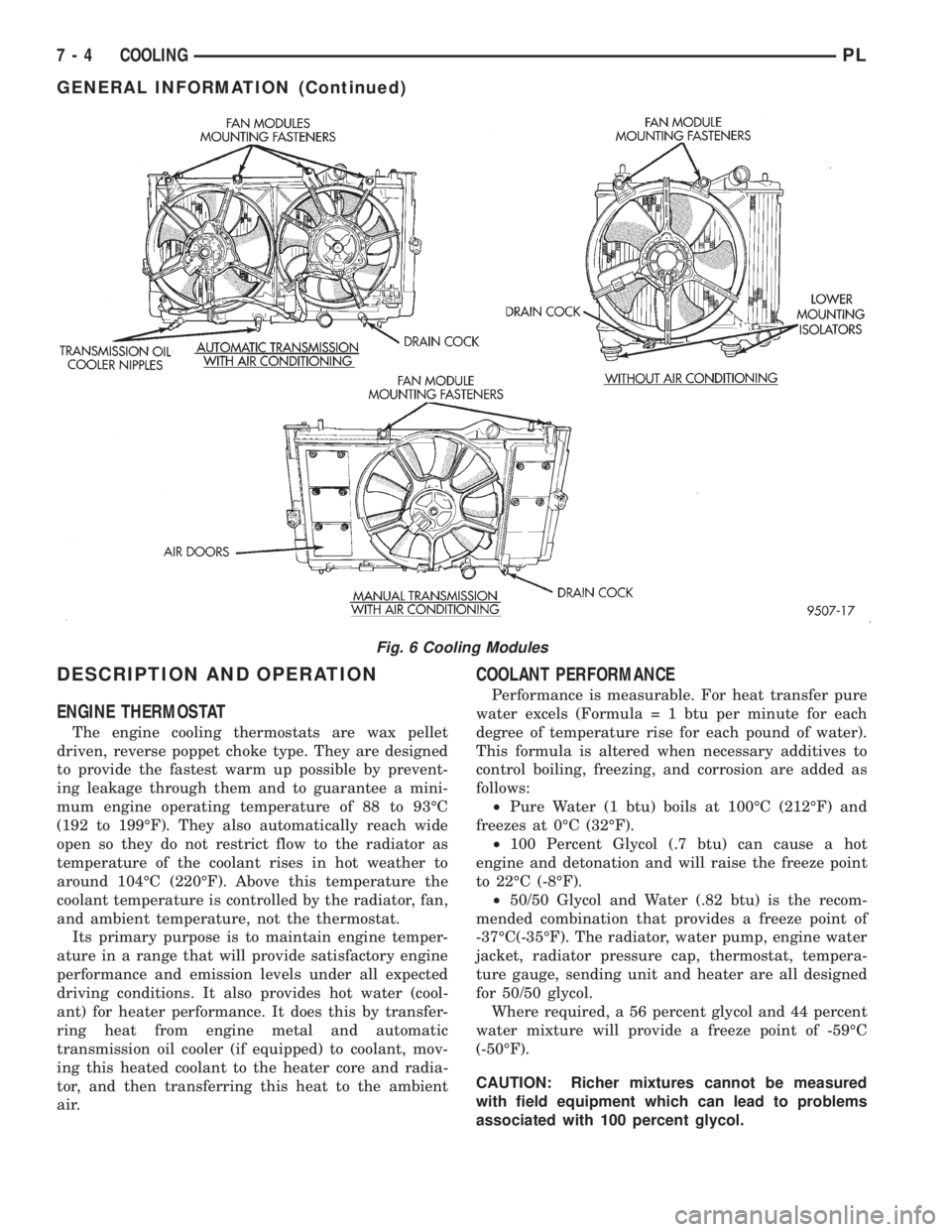
The cooling system consists of an engine cooling
module, thermostat, coolant, and a water pump to
circulate the coolant. The engine cooling module may
consist of a radiator, electric fan motor, fan, shroud,
coolant reserve system, transmission oil cooler, hoses,
clamps, air condition condenser and transmission oil lines.
²When the Engine is cold: The thermostat is
closed; the cooling system has no flow through the
radiator. The coolant flows through the engine,
heater system and bypass.
²When the Engine is warm: Thermostat is open;
the cooling system has flow through radiator, engine,
heater system and bypass.
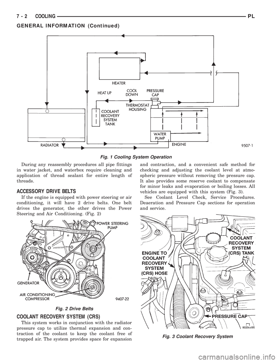
Coolant flow circuit for the 2.0L engine is shown in
(Fig. 1).
PLCOOLING 7 - 1
Page 195 of 1200
During any reassembly procedures all pipe fittings
in water jacket, and waterbox require cleaning and
application of thread sealant for entire length of
threads.
ACCESSORY DRIVE BELTS
If the engine is equipped with power steering or air
conditioning, it will have 2 drive belts. One belt
drives the generator, the other drives the Power
Steering and Air Conditioning. (Fig. 2)
COOLANT RECOVERY SYSTEM (CRS)
This system works in conjunction with the radiator
pressure cap to utilize thermal expansion and con-
traction of the coolant to keep the coolant free of
trapped air. The system provides space for expansionand contraction, and a convenient safe method for
checking and adjusting the coolant level at atmo-
spheric pressure without removing the pressure cap.
It also provides some reserve coolant to compensate
for minor leaks and evaporation or boiling losses. All
vehicles are equipped with this system (Fig. 3).
See Coolant Level Check, Service Procedures.
Deaeration and Pressure Cap sections for operation
and service.
Fig. 1 Cooling System Operation
Fig. 2 Drive Belts
Fig. 3 Coolant Recovery System
7 - 2 COOLINGPL
GENERAL INFORMATION (Continued)
Page 197 of 1200
DESCRIPTION AND OPERATION
ENGINE THERMOSTAT
The engine cooling thermostats are wax pellet
driven, reverse poppet choke type. They are designed
to provide the fastest warm up possible by prevent-
ing leakage through them and to guarantee a mini-
mum engine operating temperature of 88 to 93ÉC
(192 to 199ÉF). They also automatically reach wide
open so they do not restrict flow to the radiator as
temperature of the coolant rises in hot weather to
around 104ÉC (220ÉF). Above this temperature the
coolant temperature is controlled by the radiator, fan,
and ambient temperature, not the thermostat.
Its primary purpose is to maintain engine temper-
ature in a range that will provide satisfactory engine
performance and emission levels under all expected
driving conditions. It also provides hot water (cool-
ant) for heater performance. It does this by transfer-
ring heat from engine metal and automatic
transmission oil cooler (if equipped) to coolant, mov-
ing this heated coolant to the heater core and radia-
tor, and then transferring this heat to the ambient
air.
COOLANT PERFORMANCE
Performance is measurable. For heat transfer pure
water excels (Formula = 1 btu per minute for each
degree of temperature rise for each pound of water).
This formula is altered when necessary additives to
control boiling, freezing, and corrosion are added as
follows:
²Pure Water (1 btu) boils at 100ÉC (212ÉF) and
freezes at 0ÉC (32ÉF).
²100 Percent Glycol (.7 btu) can cause a hot
engine and detonation and will raise the freeze point
to 22ÉC (-8ÉF).
²50/50 Glycol and Water (.82 btu) is the recom-
mended combination that provides a freeze point of
-37ÉC(-35ÉF). The radiator, water pump, engine water
jacket, radiator pressure cap, thermostat, tempera-
ture gauge, sending unit and heater are all designed
for 50/50 glycol.
Where required, a 56 percent glycol and 44 percent
water mixture will provide a freeze point of -59ÉC
(-50ÉF).
CAUTION: Richer mixtures cannot be measured
with field equipment which can lead to problems
associated with 100 percent glycol.
Fig. 6 Cooling Modules
7 - 4 COOLINGPL
GENERAL INFORMATION (Continued)
Page 200 of 1200
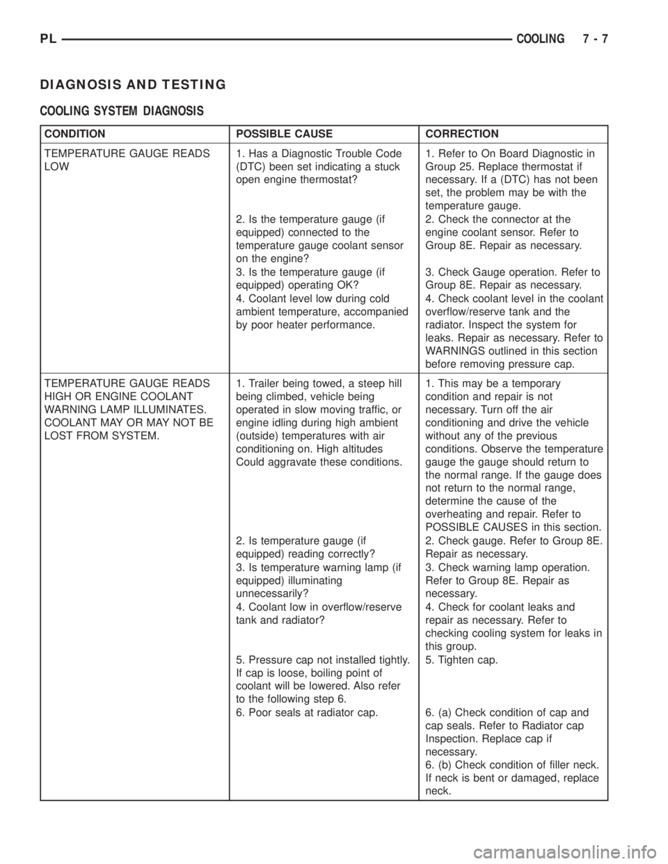
DIAGNOSIS AND TESTING
COOLING SYSTEM DIAGNOSIS
CONDITION POSSIBLE CAUSE CORRECTION
TEMPERATURE GAUGE READS
LOW1. Has a Diagnostic Trouble Code
(DTC) been set indicating a stuck
open engine thermostat?1. Refer to On Board Diagnostic in
Group 25. Replace thermostat if
necessary. If a (DTC) has not been
set, the problem may be with the
temperature gauge.
2. Is the temperature gauge (if
equipped) connected to the
temperature gauge coolant sensor
on the engine?2. Check the connector at the
engine coolant sensor. Refer to
Group 8E. Repair as necessary.
3. Is the temperature gauge (if
equipped) operating OK?3. Check Gauge operation. Refer to
Group 8E. Repair as necessary.
4. Coolant level low during cold
ambient temperature, accompanied
by poor heater performance.4. Check coolant level in the coolant
overflow/reserve tank and the
radiator. Inspect the system for
leaks. Repair as necessary. Refer to
WARNINGS outlined in this section
before removing pressure cap.
TEMPERATURE GAUGE READS
HIGH OR ENGINE COOLANT
WARNING LAMP ILLUMINATES.
COOLANT MAY OR MAY NOT BE
LOST FROM SYSTEM.1. Trailer being towed, a steep hill
being climbed, vehicle being
operated in slow moving traffic, or
engine idling during high ambient
(outside) temperatures with air
conditioning on. High altitudes
Could aggravate these conditions.1. This may be a temporary
condition and repair is not
necessary. Turn off the air
conditioning and drive the vehicle
without any of the previous
conditions. Observe the temperature
gauge the gauge should return to
the normal range. If the gauge does
not return to the normal range,
determine the cause of the
overheating and repair. Refer to
POSSIBLE CAUSES in this section.
2. Is temperature gauge (if
equipped) reading correctly?2. Check gauge. Refer to Group 8E.
Repair as necessary.
3. Is temperature warning lamp (if
equipped) illuminating
unnecessarily?3. Check warning lamp operation.
Refer to Group 8E. Repair as
necessary.
4. Coolant low in overflow/reserve
tank and radiator?4. Check for coolant leaks and
repair as necessary. Refer to
checking cooling system for leaks in
this group.
5. Pressure cap not installed tightly.
If cap is loose, boiling point of
coolant will be lowered. Also refer
to the following step 6.5. Tighten cap.
6. Poor seals at radiator cap. 6. (a) Check condition of cap and
cap seals. Refer to Radiator cap
Inspection. Replace cap if
necessary.
6. (b) Check condition of filler neck.
If neck is bent or damaged, replace
neck.
PLCOOLING 7 - 7
Page 208 of 1200
There may be internal leaks, which can be deter-
mined by removing the oil dipstick. If water globules
appear intermixed with the oil, it indicates an inter-
nal leak in the engine. If there is an internal leak,
the engine must be disassembled for repair.
PRESSURE CAP TO FILLER NECK SEAL
PRESSURE RELIEF CHECK
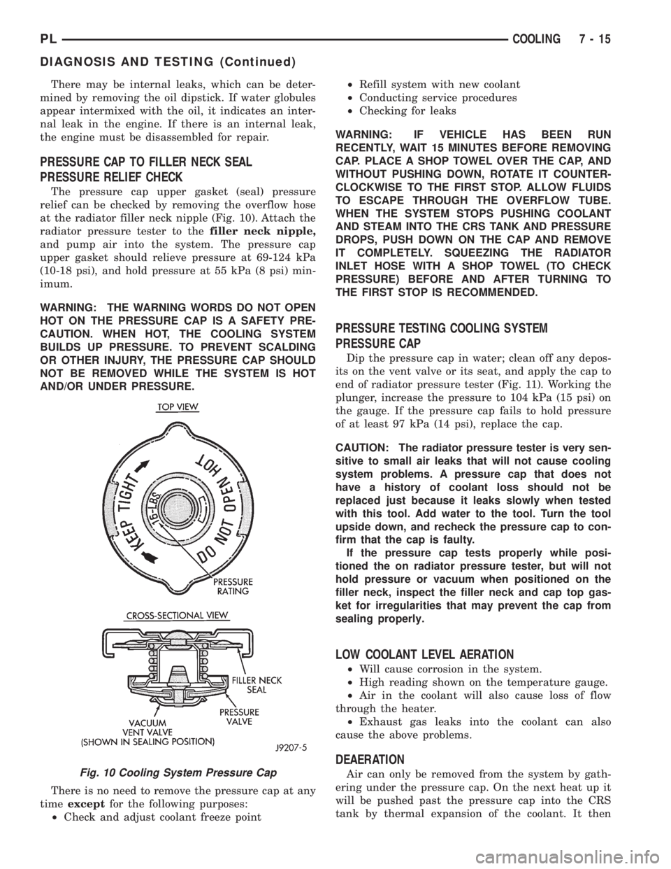
The pressure cap upper gasket (seal) pressure
relief can be checked by removing the overflow hose
at the radiator filler neck nipple (Fig. 10). Attach the
radiator pressure tester to thefiller neck nipple,
and pump air into the system. The pressure cap
upper gasket should relieve pressure at 69-124 kPa
(10-18 psi), and hold pressure at 55 kPa (8 psi) min-
imum.
WARNING: THE WARNING WORDS DO NOT OPEN
HOT ON THE PRESSURE CAP IS A SAFETY PRE-
CAUTION. WHEN HOT, THE COOLING SYSTEM
BUILDS UP PRESSURE. TO PREVENT SCALDING
OR OTHER INJURY, THE PRESSURE CAP SHOULD
NOT BE REMOVED WHILE THE SYSTEM IS HOT
AND/OR UNDER PRESSURE.
There is no need to remove the pressure cap at any
timeexceptfor the following purposes:
²Check and adjust coolant freeze point²Refill system with new coolant
²Conducting service procedures
²Checking for leaks
WARNING: IF VEHICLE HAS BEEN RUN
RECENTLY, WAIT 15 MINUTES BEFORE REMOVING
CAP. PLACE A SHOP TOWEL OVER THE CAP, AND
WITHOUT PUSHING DOWN, ROTATE IT COUNTER-
CLOCKWISE TO THE FIRST STOP. ALLOW FLUIDS
TO ESCAPE THROUGH THE OVERFLOW TUBE.
WHEN THE SYSTEM STOPS PUSHING COOLANT
AND STEAM INTO THE CRS TANK AND PRESSURE
DROPS, PUSH DOWN ON THE CAP AND REMOVE
IT COMPLETELY. SQUEEZING THE RADIATOR
INLET HOSE WITH A SHOP TOWEL (TO CHECK
PRESSURE) BEFORE AND AFTER TURNING TO
THE FIRST STOP IS RECOMMENDED.
PRESSURE TESTING COOLING SYSTEM
PRESSURE CAP
Dip the pressure cap in water; clean off any depos-
its on the vent valve or its seat, and apply the cap to
end of radiator pressure tester (Fig. 11). Working the
plunger, increase the pressure to 104 kPa (15 psi) on
the gauge. If the pressure cap fails to hold pressure
of at least 97 kPa (14 psi), replace the cap.
CAUTION: The radiator pressure tester is very sen-
sitive to small air leaks that will not cause cooling
system problems. A pressure cap that does not
have a history of coolant loss should not be
replaced just because it leaks slowly when tested
with this tool. Add water to the tool. Turn the tool
upside down, and recheck the pressure cap to con-
firm that the cap is faulty.
If the pressure cap tests properly while posi-
tioned the on radiator pressure tester, but will not
hold pressure or vacuum when positioned on the
filler neck, inspect the filler neck and cap top gas-
ket for irregularities that may prevent the cap from
sealing properly.
LOW COOLANT LEVEL AERATION
²Will cause corrosion in the system.
²High reading shown on the temperature gauge.
²Air in the coolant will also cause loss of flow
through the heater.
²Exhaust gas leaks into the coolant can also
cause the above problems.
DEAERATION
Air can only be removed from the system by gath-
ering under the pressure cap. On the next heat up it
will be pushed past the pressure cap into the CRS
tank by thermal expansion of the coolant. It thenFig. 10 Cooling System Pressure Cap
PLCOOLING 7 - 15
DIAGNOSIS AND TESTING (Continued)
Page 224 of 1200
WARNING: DO NOT CHARGE A BATTERY THAT
HAS EXCESSIVELY LOW ELECTROLYTE LEVEL.
BATTERY MAY SPARK INTERNALLY AND
EXPLODE. EXPLOSIVE GASES FORM OVER THE
BATTERY. DO NOT SMOKE, USE FLAME, OR CRE-
ATE SPARKS NEAR BATTERY. DO NOT ASSIST
BOOST OR CHARGE A FROZEN BATTERY. BAT-
TERY CASING MAY FRACTURE. BATTERY ACID IS
POISON, AND MAY CAUSE SEVERE BURNS. BAT-
TERIES CONTAIN SULFURIC ACID. AVOID CON-
TACT WITH SKIN, EYES, OR CLOTHING. IN THE
EVENT OF CONTACT, FLUSH WITH WATER AND
CALL PHYSICIAN IMMEDIATELY. KEEP OUT OF
REACH OF CHILDREN.
CAUTION: Disconnect the battery NEGATIVE cable
first, before charging battery to avoid damage to
electrical systems. Lift the red battery boot cover
from the positive cable clamp. Do not exceed 16.0
volts while charging battery. Refer to the instruc-
tions supplied with charging equipment
Battery electrolyte may bubble inside of battery
case while being charged properly. If the electrolyte
boils violently, or is discharged from the vent holes
while charging, immediately reduce charging rate or
turn off charger. Evaluate battery condition. Battery
damage may occur if charging is excessive.
Some battery chargers are equipped with polarity
sensing devices to protect the charger or battery from
being damaged if improperly connected. If the bat-
tery state of charge is too low for the polarity sensor
to detect, the sensor must be bypassed for charger to
operate. Refer to operating instructions provided
with battery charger being used.
CAUTION: Charge battery until test indicator
appears green. Do not overcharge.
It may be necessary to jiggle the battery or vehicle
to bring the green dot in the test indicator into view.
After the battery has been charged to 12.4 volts or
greater, perform a load test to determine cranking
capacity. Refer to Battery Load Test in this Group. If
the battery passes the load test, the battery is OK to
use. If battery will not pass the load test, it must be
replaced. Properly clean and inspect battery hold
downs, tray, terminals, cables, posts, and top before
completing service.
CHARGING COMPLETELY DISCHARGED BATTERY
The following procedure should be used to recharge
a completely discharged battery. Unless procedure is
properly followed, a good battery may be needlessly
replaced. Refer to Battery Charging Rate Table for
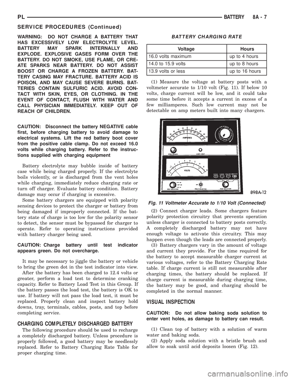
proper charging time.(1) Measure the voltage at battery posts with a
voltmeter accurate to 1/10 volt (Fig. 11). If below 10
volts, charge current will be low, and it could take
some time before it accepts a current in excess of a
few milliamperes. Such low current may not be
detectable on amp meters built into many chargers.
(2) Connect charger leads. Some chargers feature
polarity protection circuitry that prevents operation
unless charger is connected to battery posts correctly.
A completely discharged battery may not have
enough voltage to activate this circuitry. This may
happen even though the leads are connected properly.
(3) Battery chargers vary in the amount of voltage
and current they provide. For the time required for
the battery to accept measurable charger current at
various voltages, refer to the Battery Charging Rate
table. If charge current is still not measurable after
charging times, the battery should be replaced. If
charge current is measurable during charging time,
the battery may be good, and charging should be
completed in the normal manner.
VISUAL INSPECTION
CAUTION: Do not allow baking soda solution to
enter vent holes, as damage to battery can result.
(1) Clean top of battery with a solution of warm
water and baking soda.
(2) Apply soda solution with a bristle brush and
allow to soak until acid deposits loosen (Fig. 12).
BATTERY CHARGING RATE
Voltage Hours
16.0 volts maximum up to 4 hours
14.0 to 15.9 volts up to 8 hours
13.9 volts or less up to 16 hours
Fig. 11 Voltmeter Accurate to 1/10 Volt (Connected)
PLBATTERY 8A - 7
SERVICE PROCEDURES (Continued)
Page 264 of 1200
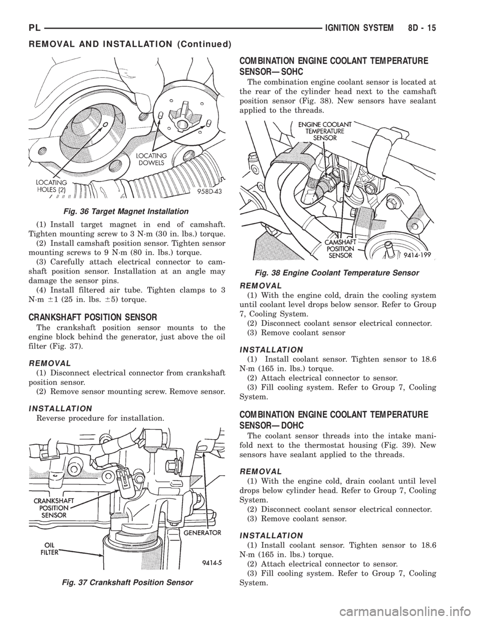
(1) Install target magnet in end of camshaft.
Tighten mounting screw to 3 N´m (30 in. lbs.) torque.
(2) Install camshaft position sensor. Tighten sensor
mounting screws to 9 N´m (80 in. lbs.) torque.
(3) Carefully attach electrical connector to cam-
shaft position sensor. Installation at an angle may
damage the sensor pins.
(4) Install filtered air tube. Tighten clamps to 3
N´m61 (25 in. lbs.65) torque.
CRANKSHAFT POSITION SENSOR
The crankshaft position sensor mounts to the
engine block behind the generator, just above the oil
filter (Fig. 37).
REMOVAL
(1) Disconnect electrical connector from crankshaft
position sensor.
(2) Remove sensor mounting screw. Remove sensor.
INSTALLATION
Reverse procedure for installation.
COMBINATION ENGINE COOLANT TEMPERATURE
SENSORÐSOHC
The combination engine coolant sensor is located at
the rear of the cylinder head next to the camshaft
position sensor (Fig. 38). New sensors have sealant
applied to the threads.
REMOVAL
(1) With the engine cold, drain the cooling system
until coolant level drops below sensor. Refer to Group
7, Cooling System.
(2) Disconnect coolant sensor electrical connector.
(3) Remove coolant sensor
INSTALLATION
(1) Install coolant sensor. Tighten sensor to 18.6
N´m (165 in. lbs.) torque.
(2) Attach electrical connector to sensor.
(3) Fill cooling system. Refer to Group 7, Cooling
System.
COMBINATION ENGINE COOLANT TEMPERATURE
SENSORÐDOHC
The coolant sensor threads into the intake mani-
fold next to the thermostat housing (Fig. 39). New
sensors have sealant applied to the threads.
REMOVAL
(1) With the engine cold, drain coolant until level
drops below cylinder head. Refer to Group 7, Cooling
System.
(2) Disconnect coolant sensor electrical connector.
(3) Remove coolant sensor.
INSTALLATION
(1) Install coolant sensor. Tighten sensor to 18.6
N´m (165 in. lbs.) torque.
(2) Attach electrical connector to sensor.
(3) Fill cooling system. Refer to Group 7, Cooling
System.
Fig. 36 Target Magnet Installation
Fig. 37 Crankshaft Position Sensor
Fig. 38 Engine Coolant Temperature Sensor
PLIGNITION SYSTEM 8D - 15
REMOVAL AND INSTALLATION (Continued)