relay DODGE NEON 1999 Service Repair Manual
[x] Cancel search | Manufacturer: DODGE, Model Year: 1999, Model line: NEON, Model: DODGE NEON 1999Pages: 1200, PDF Size: 35.29 MB
Page 150 of 1200
ANTILOCK BRAKE SYSTEM±TEVES MARK 20
INDEX
page page
DESCRIPTION AND OPERATION
ABS BRAKE SYSTEM COMPONENTS........ 71
ABS BRAKES OPERATION AND VEHICLE
PERFORMANCE....................... 69
ABS COMPONENT ABBREVIATION LIST...... 69
ABS FLUID ACCUMULATORS.............. 72
ABS FUSES............................ 73
ABS MASTER CYLINDER AND POWER BRAKE
BOOSTER............................ 71
ABS RELAYS........................... 73
ABS WARNING LAMP (YELLOW)............ 75
ANTILOCK BRAKES OPERATION
DESCRIPTION........................ 69
CONTROLLER ANTILOCK BRAKES (CAB)..... 74
HCU PUMP/MOTOR..................... 72
HYDRAULIC CIRCUITS AND VALVE
OPERATION.......................... 75
INLET VALVES AND SOLENOIDS............ 72
INTEGRATED CONTROL UNIT (ICU)......... 71
OUTLET VALVES AND SOLENOIDS.......... 72
PROPORTIONING VALVE................. 73
WHEEL SPEED SENSORS................. 73
DIAGNOSIS AND TESTING
ABS DIAGNOSTIC TROUBLE CODES........ 78
ABS DIAGNOSTICS MANUAL.............. 76
ABS GENERAL DIAGNOSTICS INFORMATION . 75
ABS SERVICE PRECAUTIONS.............. 76
ABS SYSTEM SELF DIAGNOSTICS.......... 77ABS WIRING DIAGRAM INFORMATION....... 76
BRAKE FLUID CONTAMINATION............ 80
DRB DIAGNOSTIC CONNECTOR............ 77
DRB DIAGNOSTIC SCAN TOOL USAGE...... 77
INTERMITTENT DIAGNOSTIC TROUBLE
CODES.............................. 78
PROPORTIONING VALVE................. 79
TEST DRIVING ABS COMPLAINT VEHICLE.... 80
TONEWHEEL INSPECTION................ 79
SERVICE PROCEDURES
BLEEDING TEVES MARK 20 HYDRAULIC
SYSTEM............................. 81
BRAKE FLUID LEVEL INSPECTION.......... 80
REMOVAL AND INSTALLATION
ABS GENERAL SERVICE PRECAUTIONS..... 81
ABS HYDRAULIC CONTROL UNIT........... 82
CONTROLLER ANTILOCK BRAKES (CAB)..... 86
FRONT WHEEL SPEED SENSOR........... 87
MASTER CYLINDER AND POWER BRAKE
BOOSTER............................ 86
PROPORTIONING VALVES................ 86
REAR WHEEL SPEED SENSOR............ 88
SPECIFICATIONS
BRAKE FASTENER TORQUE SPECIFICATIONS . 89
SPEED SENSOR TONE WHEEL RUNOUT..... 89
WHEEL SPEED SENSOR TO TONE WHEEL
CLEARANCE.......................... 89
DESCRIPTION AND OPERATION
ANTILOCK BRAKES OPERATION DESCRIPTION
The purpose of an Antilock Brake System (ABS) is
to prevent wheel lock-up under braking conditions on
virtually any type of road surface. Antilock Braking
is desirable because a vehicle which is stopped with-
out locking the wheels will retain directional stability
and some steering capability. This allows the driver
to retain greater control of the vehicle during brak-
ing.
This section of the service manual covers the
description and on car service for the ITT Teves
Mark 20 ABS Brake System. If other service is
required on the non ABS related components of the
brake system, refer to the appropriate section in this
group of the service manual for the specific service
procedure required.
ABS COMPONENT ABBREVIATION LIST
In this section of the service manual, several
abbreviations are used for the components of the
Teves Mark 20 ABS Brake System. They are listed
below for your reference.
²CAB±Controller Antilock Brake
²ICU±Integrated Control Unit
²HCU±Hydraulic Control Unit
²ABS±Antilock Brake System
²PSI±Pounds Per Square Inch (pressure)
²WSS±Wheel Speed Sensor
²FWD±Front Wheel Drive
²DTC±Diagnostic Trouble Code
ABS BRAKES OPERATION AND VEHICLE
PERFORMANCE
This ABS System represents the current state-of-
the-art in vehicle braking systems and offers the
driver increased safety and control during braking.
PLBRAKES 5 - 69
Page 154 of 1200
ABS FUSES
The fuse for the ABS pump motor and the ABS
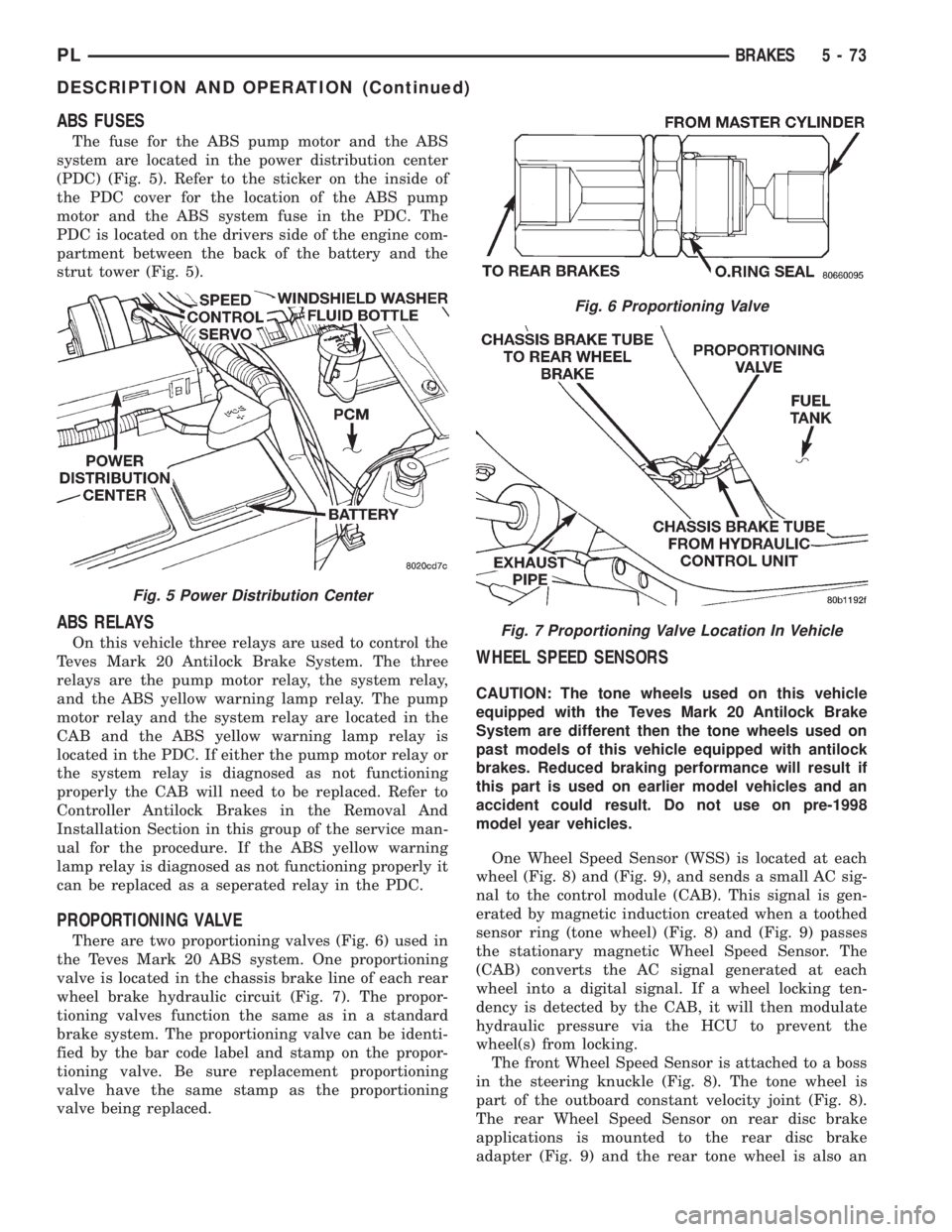
system are located in the power distribution center
(PDC) (Fig. 5). Refer to the sticker on the inside of
the PDC cover for the location of the ABS pump
motor and the ABS system fuse in the PDC. The
PDC is located on the drivers side of the engine com-
partment between the back of the battery and the
strut tower (Fig. 5).
ABS RELAYS
On this vehicle three relays are used to control the
Teves Mark 20 Antilock Brake System. The three
relays are the pump motor relay, the system relay,
and the ABS yellow warning lamp relay. The pump
motor relay and the system relay are located in the
CAB and the ABS yellow warning lamp relay is
located in the PDC. If either the pump motor relay or
the system relay is diagnosed as not functioning
properly the CAB will need to be replaced. Refer to
Controller Antilock Brakes in the Removal And
Installation Section in this group of the service man-
ual for the procedure. If the ABS yellow warning
lamp relay is diagnosed as not functioning properly it
can be replaced as a seperated relay in the PDC.
PROPORTIONING VALVE
There are two proportioning valves (Fig. 6) used in
the Teves Mark 20 ABS system. One proportioning
valve is located in the chassis brake line of each rear
wheel brake hydraulic circuit (Fig. 7). The propor-
tioning valves function the same as in a standard
brake system. The proportioning valve can be identi-
fied by the bar code label and stamp on the propor-
tioning valve. Be sure replacement proportioning
valve have the same stamp as the proportioning
valve being replaced.
WHEEL SPEED SENSORS
CAUTION: The tone wheels used on this vehicle
equipped with the Teves Mark 20 Antilock Brake
System are different then the tone wheels used on
past models of this vehicle equipped with antilock
brakes. Reduced braking performance will result if
this part is used on earlier model vehicles and an
accident could result. Do not use on pre-1998
model year vehicles.
One Wheel Speed Sensor (WSS) is located at each
wheel (Fig. 8) and (Fig. 9), and sends a small AC sig-
nal to the control module (CAB). This signal is gen-
erated by magnetic induction created when a toothed
sensor ring (tone wheel) (Fig. 8) and (Fig. 9) passes
the stationary magnetic Wheel Speed Sensor. The
(CAB) converts the AC signal generated at each
wheel into a digital signal. If a wheel locking ten-
dency is detected by the CAB, it will then modulate
hydraulic pressure via the HCU to prevent the
wheel(s) from locking.
The front Wheel Speed Sensor is attached to a boss
in the steering knuckle (Fig. 8). The tone wheel is
part of the outboard constant velocity joint (Fig. 8).
The rear Wheel Speed Sensor on rear disc brake
applications is mounted to the rear disc brake
adapter (Fig. 9) and the rear tone wheel is also an
Fig. 5 Power Distribution Center
Fig. 6 Proportioning Valve
Fig. 7 Proportioning Valve Location In Vehicle
PLBRAKES 5 - 73
DESCRIPTION AND OPERATION (Continued)
Page 156 of 1200
cally cleared from the CAB memory after the identi-
cal fault has not been seen during the next 255 key
cycles of vehicle operation.
CONTROLLER ANTILOCK BRAKE INPUTS
²Four wheel speed sensors.
²Stop lamp switch.
²Ignition switch.
²System relay voltage.
²Ground.
²Diagnostics Communications (CCD)
CONTROLLER ANTILOCK BRAKE OUTPUTS
²ABS warning lamp actuation.
²Diagnostic communication. (CCD)
ABS WARNING LAMP (YELLOW)
The ABS system uses a yellow colored ABS Warn-
ing Lamp. The ABS warning lamp is located on the
lower left side of the instrument pane. The purpose
of the warning lamp is discussed in detail below.
The ABS warning lamp will turn on when the CAB
detects a condition which results in a shutdown of
ABS function. When the ignition key is turned to the
on position, the ABS Warning Lamp is on until the
CAB completes its self tests and turns the lamp off
(approximately 4 seconds after the ignition switch is
turned on). Under most conditions, when the ABS
warning lamp is on, only the ABS function of the
brake system is affected. The standard brake system
and the ability to stop the car will not be affected
when only the ABS warning lamp is on.
The ABS warning lamp is controlled by the CAB.
The CAB turns on the yellow ABS warning lamp by
grounding the circuit.
HYDRAULIC CIRCUITS AND VALVE OPERATION
Through the following operation descriptions the
function of the various hydraulic control valves in the
ABS will be described. The fluid control valves men-
tioned below, control the flow of pressurized brake
fluid to the wheel brakes during the different modes
of ABS braking.
For explanation purposes, all wheel speed sensors
except the right front are sending the same wheel
speed information. The following diagrams show only
the right front wheel in a antilock braking condition.
NORMAL BRAKING HYDRAULIC CIRCUIT AND
SOLENOID VALVE FUNCTION
This condition is the normal operation of the vehi-
cles base brake hydraulic system. The hydraulic sys-
tem circuit diagram (Fig. 11) shows a situation where
no wheel spin or slip is occurring relative to the
speed of the vehicle. The driver is applying the brake
pedal to build pressure in the brake hydraulic system
to apply the brakes and stop the vehicle.
TEVES MARK 20 ABS CIRCUIT AND
SOLENOID VALVE FUNCTION
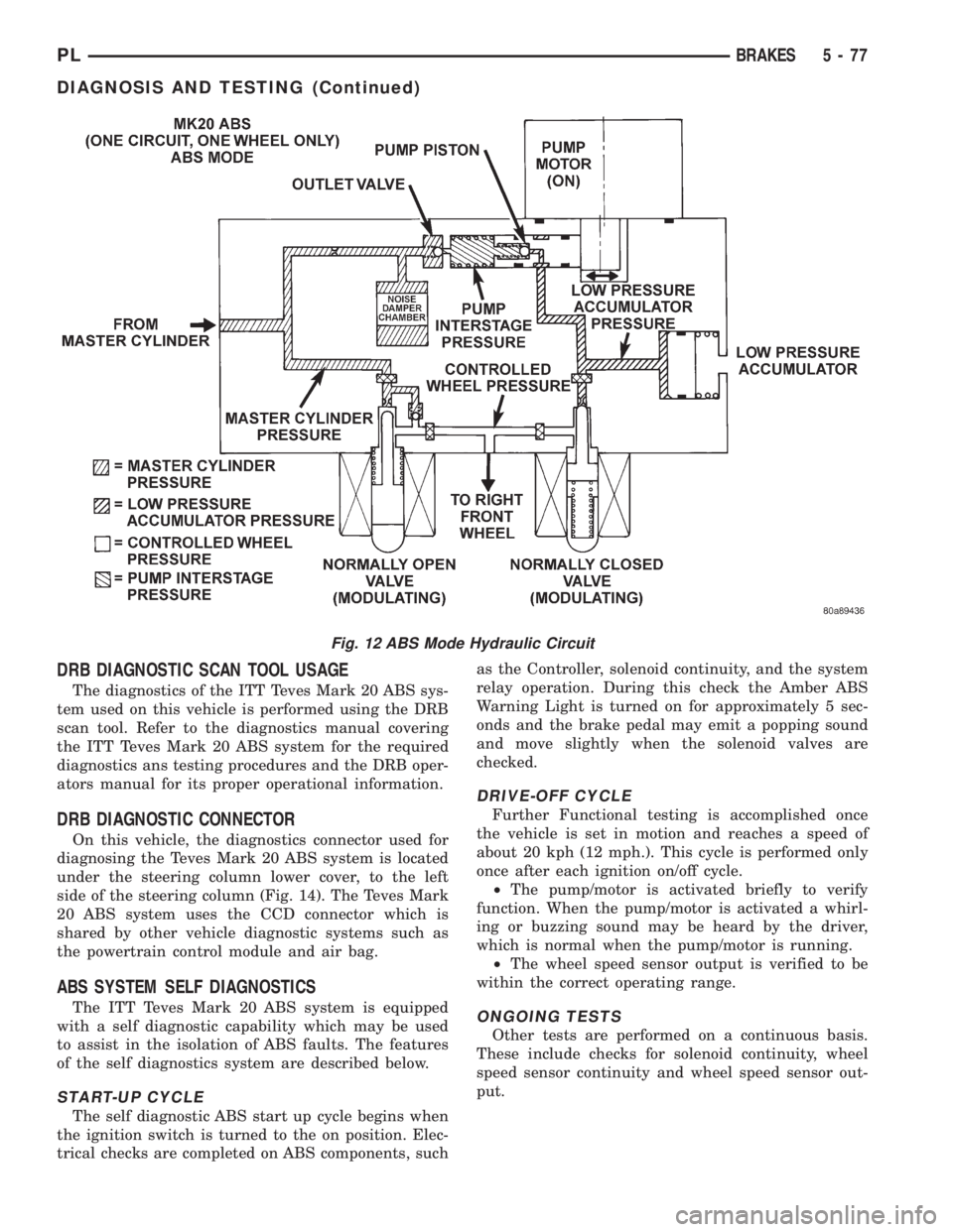
This hydraulic circuit diagram (Fig. 12) shows the
vehicle in the ABS braking mode. This hydraulic cir-
cuit (Fig. 12) shows a situation where one wheel is
slipping because the driver is attempting to stop the
vehicle at a faster rate than the surface the vehicle's
tires are on will allow. The normally open and nor-
mally closed valves modulate the brake hydraulic
pressure as required. The pump/motor is switched on
so that the brake fluid from the low pressure accu-
mulators is returned to the master cylinder circuits.
The brake fluid will then be routed to either the mas-
ter cylinder or the wheel brake depending on the
position of the normally open valve.
TEVES MARK 20 SECONDARY ABS CIRCUIT
AND SOLENOID VALVE FUNCTION
This hydraulic circuit diagram (Fig. 13) shows the
vehicle in the ABS braking mode. This hydraulic cir-
cuit (Fig. 13) shows a situation where one wheel is
slipping because the driver is attempting to stop the
vehicle at a faster rate than the surface the vehicle's
tires are on will allow. The normally open and nor-
mally closed valves modulate the brake hydraulic
pressure as required. The pump/motor is switched on
so that the brake fluid from the low pressure accu-
mulators is returned to the master cylinder circuits.
The brake fluid will then be routed to either the mas-
ter cylinder or the wheel brake depending on the
position of the normally open valve. A volume of 1.2
cc's of brake fluid is taken in by the lip seal saver
(Fig. 13) to protect the lip seals on the piston of the
master cylinder.
DIAGNOSIS AND TESTING
ABS GENERAL DIAGNOSTICS INFORMATION
This section contains the information necessary to
diagnose the ITT Teves Mark 20 ABS Brake System.
Specifically, this section should be used to help diag-
nose conditions which result in any of the following:
(1) ABS Warning Lamp turned on.
(2) Brakes Lock-up on hard application
Diagnosis of base brake conditions which are obvi-
ously mechanical in nature should be directed to
Group 5 Brakes in this service manual. This includes
brake noise, brake pulsation, lack of power assist,
parking brake, Red BRAKE Warning Lamp lighting,
or vehicle vibration during normal braking.
Many conditions that generate customer com-
plaints may be normal operating conditions, but are
judged to be a problem due to not being familiar with
the ABS system. These conditions can be recognized
without performing extensive diagnostic work, given
adequate understanding of the operating principles
PLBRAKES 5 - 75
DESCRIPTION AND OPERATION (Continued)
Page 158 of 1200
DRB DIAGNOSTIC SCAN TOOL USAGE
The diagnostics of the ITT Teves Mark 20 ABS sys-
tem used on this vehicle is performed using the DRB
scan tool. Refer to the diagnostics manual covering
the ITT Teves Mark 20 ABS system for the required
diagnostics ans testing procedures and the DRB oper-
ators manual for its proper operational information.
DRB DIAGNOSTIC CONNECTOR
On this vehicle, the diagnostics connector used for
diagnosing the Teves Mark 20 ABS system is located
under the steering column lower cover, to the left
side of the steering column (Fig. 14). The Teves Mark
20 ABS system uses the CCD connector which is
shared by other vehicle diagnostic systems such as
the powertrain control module and air bag.
ABS SYSTEM SELF DIAGNOSTICS
The ITT Teves Mark 20 ABS system is equipped
with a self diagnostic capability which may be used
to assist in the isolation of ABS faults. The features
of the self diagnostics system are described below.
START-UP CYCLE
The self diagnostic ABS start up cycle begins when
the ignition switch is turned to the on position. Elec-
trical checks are completed on ABS components, suchas the Controller, solenoid continuity, and the system
relay operation. During this check the Amber ABS
Warning Light is turned on for approximately 5 sec-
onds and the brake pedal may emit a popping sound
and move slightly when the solenoid valves are
checked.
DRIVE-OFF CYCLE
Further Functional testing is accomplished once
the vehicle is set in motion and reaches a speed of
about 20 kph (12 mph.). This cycle is performed only
once after each ignition on/off cycle.
²The pump/motor is activated briefly to verify
function. When the pump/motor is activated a whirl-
ing or buzzing sound may be heard by the driver,
which is normal when the pump/motor is running.
²The wheel speed sensor output is verified to be
within the correct operating range.
ONGOING TESTS
Other tests are performed on a continuous basis.
These include checks for solenoid continuity, wheel
speed sensor continuity and wheel speed sensor out-
put.
Fig. 12 ABS Mode Hydraulic Circuit
PLBRAKES 5 - 77
DIAGNOSIS AND TESTING (Continued)
Page 160 of 1200
A visual inspection for loose, disconnected, or mis-
routed wires should be done before attempting to
diagnose or service the ITT Teves Mark 20 antilock
brake system. A visual inspection will eliminate
unnecessary testing and diagnostics time. A thorough
visual inspection will include the following compo-
nents and areas of the vehicle.
(1) Inspect fuses in the power distribution center
(PDC) and the wiring junction block. Verify that all
fuses are fully inserted into the PDC and wring junc-
tion block. A label on the underside of the PDC cover
identifies the locations of the ABS fuses in the PDC.
(2) Inspect the 25-way electrical connector at the
CAB for damage, spread or backed-out wiring termi-
nals. Verify that the 25-way connector is fully
inserted in the socket on the CAB. Be sure that wires
are not stretched tight or pulled out of the connector.
(3) Verify that all the wheel speed sensor connec-
tions are secure.
(4) Poor mating of connector halves or terminals
not fully seated in the connector body.
(5) Improperly formed or damaged terminals. All
connector terminals in a suspect circuit should be
carefully reformed to increase contact tension.
(6) Poor terminal to wire connection. This requires
removing the terminal from the connector body to
inspect.
(7) Pin presence in the connector assembly
(8) Proper ground connections. Check all ground
connections for signs of corrosion, tight fasteners, or
other potential defects. Refer to wiring diagram man-
ual for ground locations.
(9) Problems with main power sources of the vehi-
cle. Inspect battery, generator, ignition circuits and
other related relays and fuses.
(10) If a visual check does not find the cause of the
problem, operate the car in an attempt to duplicate
the condition and record the trouble code.
(11) Most failures of the ABS system will disable
ABS function for the entire ignition cycle even if the
fault clears before key-off. There are some failure
conditions, however, which will allow ABS operation
to resume during the ignition cycle in which a failure
occurred if the failure conditions are no longer
present. The following conditions may result in inter-
mittent illumination of the ABS Warning Lamp. All
other failures will cause the lamp to remain on until
the ignition switch is turned off. Circuits involving
these inputs to the CAB should be investigated if a
complaint of intermittent warning system operation
is encountered.
(12) Low system voltage. If Low System Voltage is
detected by the CAB, the CAB will turn on the ABS
Warning Lamp until normal system voltage is
achieved. Once normal voltage is seen at the CAB,
normal operation resumes.(13) High system voltage. If high system voltage is
detected by the CAB, the CAB will turn on the
Amber ABS Warning Lamp until normal system volt-
age is achieved. Once normal voltage is again
detected by the CAB, normal ABS operation resumes.
(14) Additionally, any condition which results in
interruption of electrical current to the CAB or mod-
ulator assembly may cause the ABS Warning Lamp
to turn on intermittently.
(15) The body controller can turn on the (yellow)
ABS warning lamp if CCD communication between
the body controller and the CAB is interupted.
TONEWHEEL INSPECTION
CAUTION: The tone wheels used on this vehicle
equipped with the Teves Mark 20 Antilock Brake
System are different then those used on past mod-
els of this vehicle equipped with antilock brakes.
Reduced braking performance will result if this part
is used on earlier model vehicles and an accident
could result. Do not use on pre-1998 model year
vehicles.
Carefully inspect tonewheel at the suspected faulty
wheel speed sensor for missing, chipped or broken
teeth, this can cause erratic speed sensor signals.
Tonewheels should show no evidence of contact
with the wheel speed sensors. If contact was made,
determine cause and correct before replacing the
wheel speed sensor.
Excessive runout of the tonewheel can cause
erratic wheel speed sensor signals. Refer to Tone-
wheel Runout in the Specification Section in this sec-
tion of the service manual for the tonewheel runout
specification. Replace drive shaft assembly or rear
hub/bearing assembly if tonewheel runout exceeds
the specification.
Inspect tonewheels for looseness on their mounting
surfaces. Tonewheels are pressed onto their mounting
surfaces and should not rotate independently from
the mounting surface.
Check the wheel speed sensor head alignment to
the tone wheel. Also check the gap between the speed
sensor head and the tone wheel to ensure it is at
specification. Refer to Wheel Speed Sensor Clearance
in the Specification Section in this section of the ser-
vice manual.
PROPORTIONING VALVE
CAUTION: Proportioning valves should never be
disassembled.
If premature rear wheel skid occurs on a hard
brake application, it could be an indication that a
PLBRAKES 5 - 79
DIAGNOSIS AND TESTING (Continued)
Page 173 of 1200
The clutch cable has a unique self-adjuster mecha-
nism built into the cable which compensates for
clutch disc wear. The cable requires no maintenance
or lubrication. There are no serviceable components
on the cable assembly.
The clutch pedal is connected to the cable through
a plastic spacer. The upper end of the clutch pedal
pivots in the pedal bracket on two nylon bushings
and a shaft. These bushings are greased at assembly
and do not require periodic lubrication.
CLUTCH DISC AND COVER APPLICATION
The 2.0 single overhead cam engine uses a 216 mm
(8.5 in.) clutch disc. The manual transaxle is avail-
able only with the 2.0 liter engine.
CLUTCH REPLACEMENT
The transaxle must be removed to service the
clutch disc, pressure plate, flywheel/drive plate,
and/or clutch release bearing and lever.
DESCRIPTION AND OPERATION
CLUTCH CABLE
The manual transaxle clutch release system has a
unique self-adjusting mechanism to compensate for
clutch disc wear. This adjuster mechanism is located
within the clutch cable assembly. The preload spring
maintains tension on the cable. This tension keeps
the clutch release bearing continuously loaded
against the fingers of the clutch cover assembly.
CLUTCH PEDAL POSITION SWITCH
The clutch pedal position switch functions as a
safety interlock device. It prevents possible engine
cranking with the clutch engaged.
The clutch pedal position switch is wired in series
between the starter relay coil and the ignition
switch.
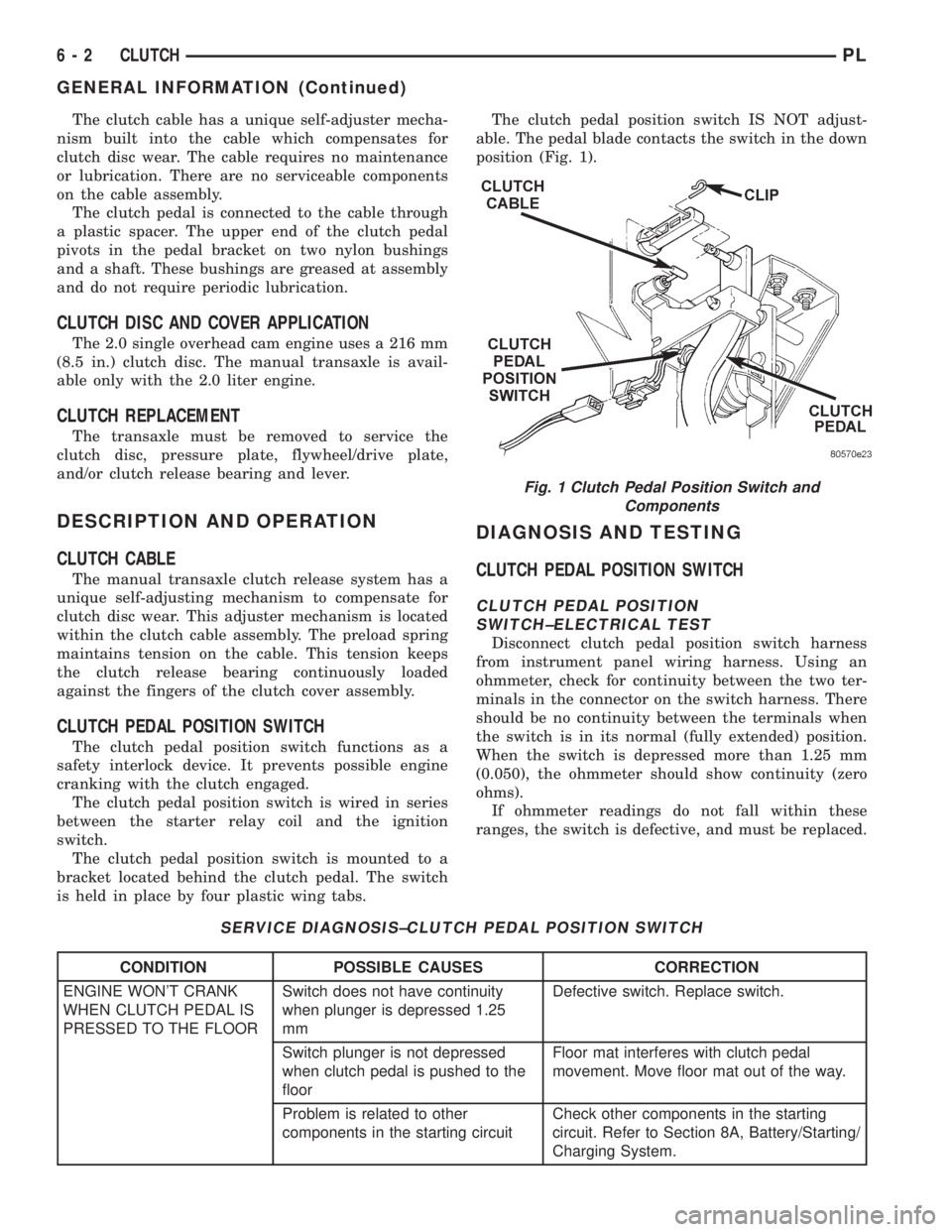
The clutch pedal position switch is mounted to a
bracket located behind the clutch pedal. The switch
is held in place by four plastic wing tabs.The clutch pedal position switch IS NOT adjust-
able. The pedal blade contacts the switch in the down
position (Fig. 1).
DIAGNOSIS AND TESTING
CLUTCH PEDAL POSITION SWITCH
CLUTCH PEDAL POSITION
SWITCH±ELECTRICAL TEST
Disconnect clutch pedal position switch harness
from instrument panel wiring harness. Using an
ohmmeter, check for continuity between the two ter-
minals in the connector on the switch harness. There
should be no continuity between the terminals when
the switch is in its normal (fully extended) position.
When the switch is depressed more than 1.25 mm
(0.050), the ohmmeter should show continuity (zero
ohms).
If ohmmeter readings do not fall within these
ranges, the switch is defective, and must be replaced.
SERVICE DIAGNOSIS±CLUTCH PEDAL POSITION SWITCH
CONDITION POSSIBLE CAUSES CORRECTION
ENGINE WON'T CRANK
WHEN CLUTCH PEDAL IS
PRESSED TO THE FLOORSwitch does not have continuity
when plunger is depressed 1.25
mmDefective switch. Replace switch.
Switch plunger is not depressed
when clutch pedal is pushed to the
floorFloor mat interferes with clutch pedal
movement. Move floor mat out of the way.
Problem is related to other
components in the starting circuitCheck other components in the starting
circuit. Refer to Section 8A, Battery/Starting/
Charging System.
Fig. 1 Clutch Pedal Position Switch and
Components
6 - 2 CLUTCHPL
GENERAL INFORMATION (Continued)
Page 207 of 1200
WATER PUMP DIAGNOSIS
A quick flow test to tell whether or not the pump is
working is to see if the heater warms properly. A
defective pump will not be able to circulate heated
coolant through the long heater hose.
Another flow test to help determine pump opera-
tion.
WARNING: DO NOT remove radiator cap if the cool-
ing system is hot or under pressure.
(1) Remove radiator cap.
(2) Remove a small amount of coolant from the
system, start the engine and warm up until thermo-
stat opens. With the thermostat open and coolant
level low you will see if the water pump is pumping
coolant through the system.
COOLING SYSTEM FLOW CHECK
To determine whether coolant is flowing through
the cooling system, use the following procedures:
(1) If engine is cold, idle engine until normal oper-
ating temperature is reached. Then feel the upper
radiator hose. If it is hot, coolant is circulating.
WARNING: DO NOT REMOVE THE COOLING SYS-
TEM PRESSURE CAP WITH THE SYSTEM HOT AND
UNDER PRESSURE BECAUSE SERIOUS BURNS
FROM COOLANT CAN OCCUR.
(2) Remove pressure cap when engine is cold,
remove small amount of coolant Idle engine until
thermostat opens, you should observe coolant flow
while looking down the filler neck. Once flow is
detected install the pressure cap.
RADIATOR FAN CONTROL
Fan control is accomplished two ways. The fan
always runs when the air conditioning compressor
clutch is engaged. In addition to this control, the fan
is turned on by the temperature of the coolant which
is sensed by the coolant temperature sensor which
sends the message to the Powertrain Control Module
(PCM). The (PCM) turns on the fan through the
Solid State Fan Relay. The Solid State Fan Relay is
located on the left front inner frame just behind the
radiator. See Wiring Diagrams Manual for circuity
and diagnostics provided.
Switching through the (PCM) provides fan control
for the following conditions.
²The fan will not run during cranking until the
engine starts no matter what the coolant tempera-
ture is.
²Fan will run when the air conditioning clutch is
engaged and low pressure cutout switch is closed.
²Fan will run at vehicle speeds above about 40
mph only if coolant temperature reaches 110ÉC(230ÉF). It will turn off when the temperature drops
to 104ÉC (220ÉF). At speeds below 40 mph the fan
switches on at 102ÉC (215ÉF) and off at 93ÉC (200ÉF).
Refer to Radiator Fan Control Module Group 14,
Fuel Injection for more information.
ELECTRIC FAN MOTOR TEST
Refer to Powertrain Diagnostic Manual for procedure.
TESTING COOLING SYSTEM FOR LEAKS
The system should be full. With the engine not
running, wipe the filler neck sealing seat clean.
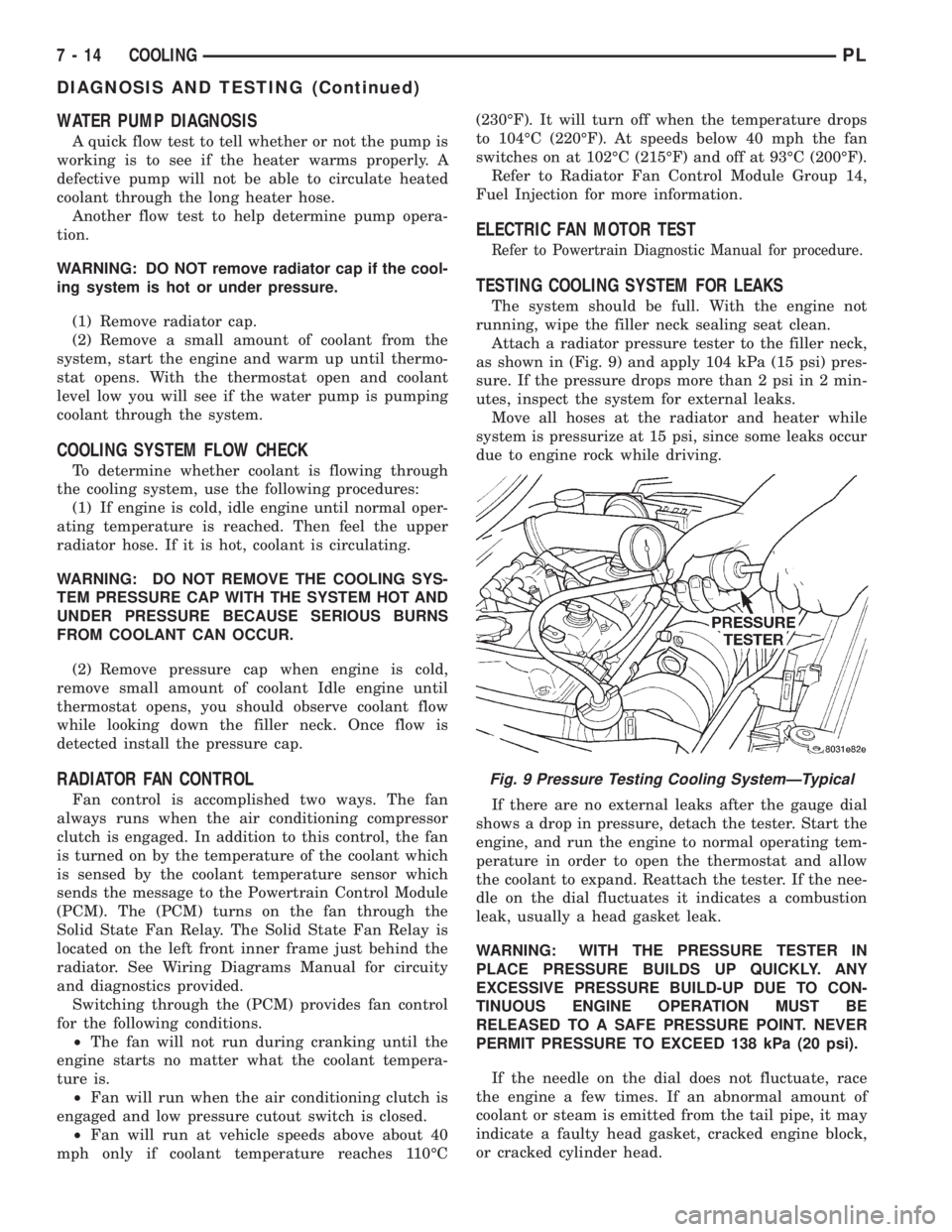
Attach a radiator pressure tester to the filler neck,
as shown in (Fig. 9) and apply 104 kPa (15 psi) pres-
sure. If the pressure drops more than 2 psi in 2 min-
utes, inspect the system for external leaks.
Move all hoses at the radiator and heater while
system is pressurize at 15 psi, since some leaks occur
due to engine rock while driving.
If there are no external leaks after the gauge dial
shows a drop in pressure, detach the tester. Start the
engine, and run the engine to normal operating tem-
perature in order to open the thermostat and allow
the coolant to expand. Reattach the tester. If the nee-
dle on the dial fluctuates it indicates a combustion
leak, usually a head gasket leak.
WARNING: WITH THE PRESSURE TESTER IN
PLACE PRESSURE BUILDS UP QUICKLY. ANY
EXCESSIVE PRESSURE BUILD-UP DUE TO CON-
TINUOUS ENGINE OPERATION MUST BE
RELEASED TO A SAFE PRESSURE POINT. NEVER
PERMIT PRESSURE TO EXCEED 138 kPa (20 psi).
If the needle on the dial does not fluctuate, race
the engine a few times. If an abnormal amount of
coolant or steam is emitted from the tail pipe, it may
indicate a faulty head gasket, cracked engine block,
or cracked cylinder head.
Fig. 9 Pressure Testing Cooling SystemÐTypical
7 - 14 COOLINGPL
DIAGNOSIS AND TESTING (Continued)
Page 228 of 1200
STARTING
CONTENTS
page page
GENERAL INFORMATION
BOSCH STARTER........................ 1
INTRODUCTION......................... 1
SUPPLY CIRCUIT AND CONTROL CIRCUIT.... 1
DIAGNOSIS AND TESTING
FEED CIRCUIT RESISTANCE TEST........... 2
FEED CIRCUIT TEST...................... 2
STARTER CONTROL CIRCUIT.............. 1STARTING SYSTEM TEST................. 4
REMOVAL AND INSTALLATION
SAFETY SWITCHES...................... 6
STARTER RELAY........................ 7
STARTER .............................. 6
SPECIFICATIONS
STARTER .............................. 7
TORQUE............................... 7
GENERAL INFORMATION
INTRODUCTION
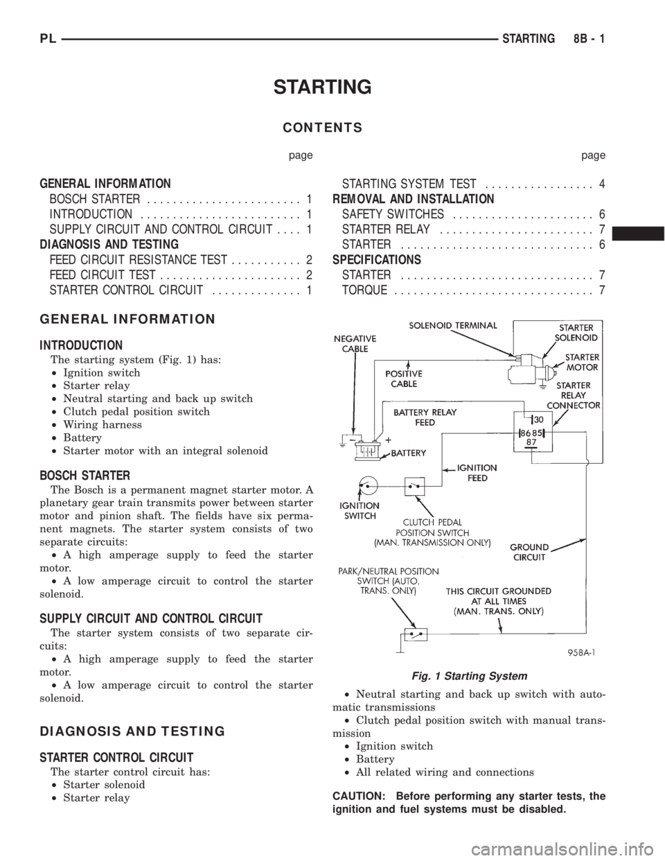
The starting system (Fig. 1) has:
²Ignition switch
²Starter relay
²Neutral starting and back up switch
²Clutch pedal position switch
²Wiring harness
²Battery
²Starter motor with an integral solenoid
BOSCH STARTER
The Bosch is a permanent magnet starter motor. A
planetary gear train transmits power between starter
motor and pinion shaft. The fields have six perma-
nent magnets. The starter system consists of two
separate circuits:
²A high amperage supply to feed the starter
motor.
²A low amperage circuit to control the starter
solenoid.
SUPPLY CIRCUIT AND CONTROL CIRCUIT
The starter system consists of two separate cir-
cuits:
²A high amperage supply to feed the starter
motor.
²A low amperage circuit to control the starter
solenoid.
DIAGNOSIS AND TESTING
STARTER CONTROL CIRCUIT
The starter control circuit has:
²Starter solenoid
²Starter relay²Neutral starting and back up switch with auto-
matic transmissions
²Clutch pedal position switch with manual trans-
mission
²Ignition switch
²Battery
²All related wiring and connections
CAUTION: Before performing any starter tests, the
ignition and fuel systems must be disabled.
Fig. 1 Starting System
PLSTARTING 8B - 1
Page 229 of 1200
To disable the ignition and fuel systems, disconnect
the Automatic Shutdown Relay (ASD). The ASD relay
is located in the Power Distribution Center (PDC).
Refer to the PDC cover for proper relay location.
FEED CIRCUIT RESISTANCE TEST
Before proceeding with this operation, review Diag-
nostic Preparation and Starter Feed Circuit Tests.
The following operation will require a voltmeter,
accurate to 1/10 of a volt.
CAUTION: Ignition system also must be disabled
to prevent engine start while performing the follow-
ing tests.
(1) To disable the ignition and fuel systems, dis-
connect the Automatic Shutdown Relay (ASD). The
ASD relay is located in the Power Distribution Cen-
ter (PDC). Refer to the PDC cover for proper relay
location.
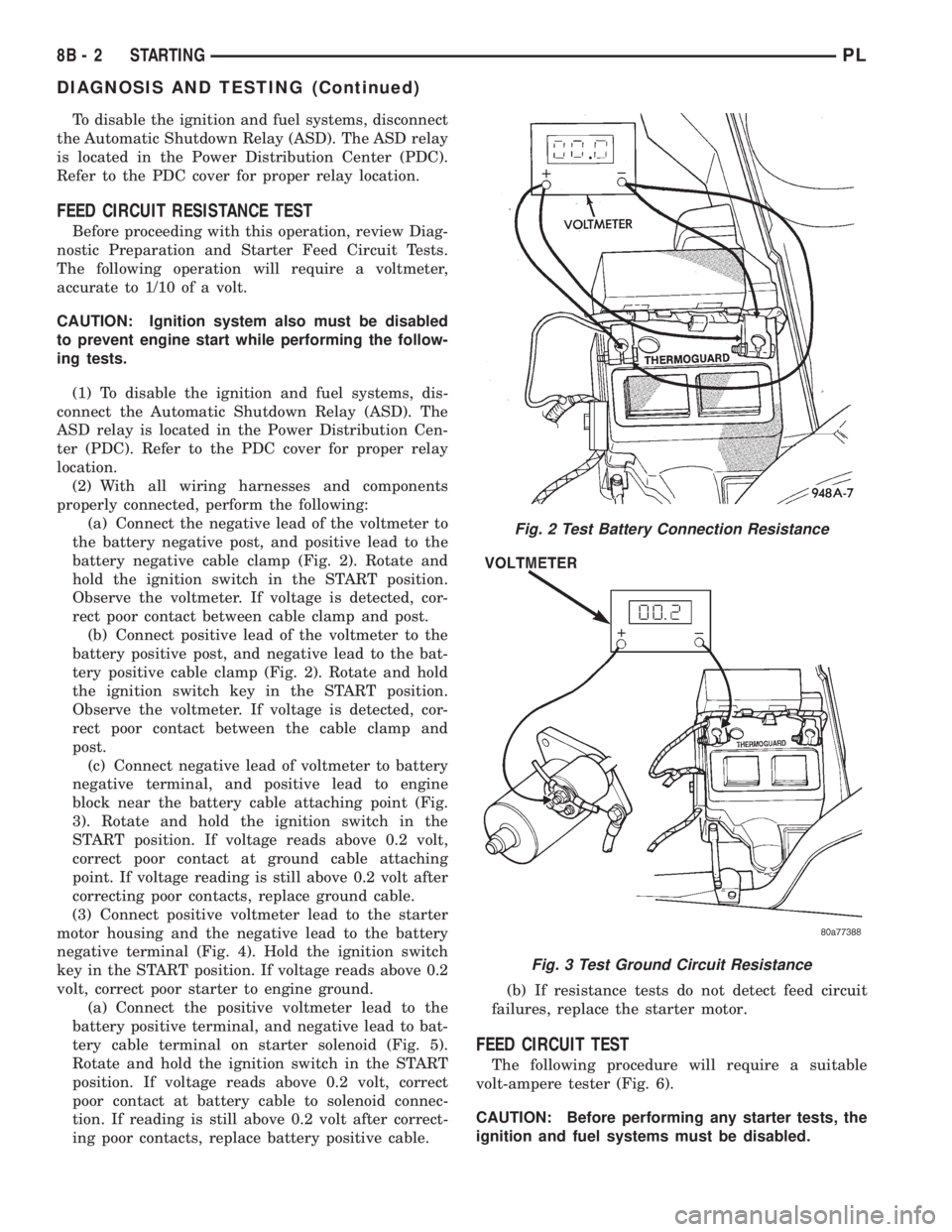
(2) With all wiring harnesses and components
properly connected, perform the following:
(a) Connect the negative lead of the voltmeter to
the battery negative post, and positive lead to the
battery negative cable clamp (Fig. 2). Rotate and
hold the ignition switch in the START position.
Observe the voltmeter. If voltage is detected, cor-
rect poor contact between cable clamp and post.
(b) Connect positive lead of the voltmeter to the
battery positive post, and negative lead to the bat-
tery positive cable clamp (Fig. 2). Rotate and hold
the ignition switch key in the START position.
Observe the voltmeter. If voltage is detected, cor-
rect poor contact between the cable clamp and
post.
(c) Connect negative lead of voltmeter to battery
negative terminal, and positive lead to engine
block near the battery cable attaching point (Fig.
3). Rotate and hold the ignition switch in the
START position. If voltage reads above 0.2 volt,
correct poor contact at ground cable attaching
point. If voltage reading is still above 0.2 volt after
correcting poor contacts, replace ground cable.
(3) Connect positive voltmeter lead to the starter
motor housing and the negative lead to the battery
negative terminal (Fig. 4). Hold the ignition switch
key in the START position. If voltage reads above 0.2
volt, correct poor starter to engine ground.
(a) Connect the positive voltmeter lead to the
battery positive terminal, and negative lead to bat-
tery cable terminal on starter solenoid (Fig. 5).
Rotate and hold the ignition switch in the START
position. If voltage reads above 0.2 volt, correct
poor contact at battery cable to solenoid connec-
tion. If reading is still above 0.2 volt after correct-
ing poor contacts, replace battery positive cable.(b) If resistance tests do not detect feed circuit
failures, replace the starter motor.
FEED CIRCUIT TEST
The following procedure will require a suitable
volt-ampere tester (Fig. 6).
CAUTION: Before performing any starter tests, the
ignition and fuel systems must be disabled.
Fig. 2 Test Battery Connection Resistance
Fig. 3 Test Ground Circuit Resistance
8B - 2 STARTINGPL
DIAGNOSIS AND TESTING (Continued)
Page 230 of 1200
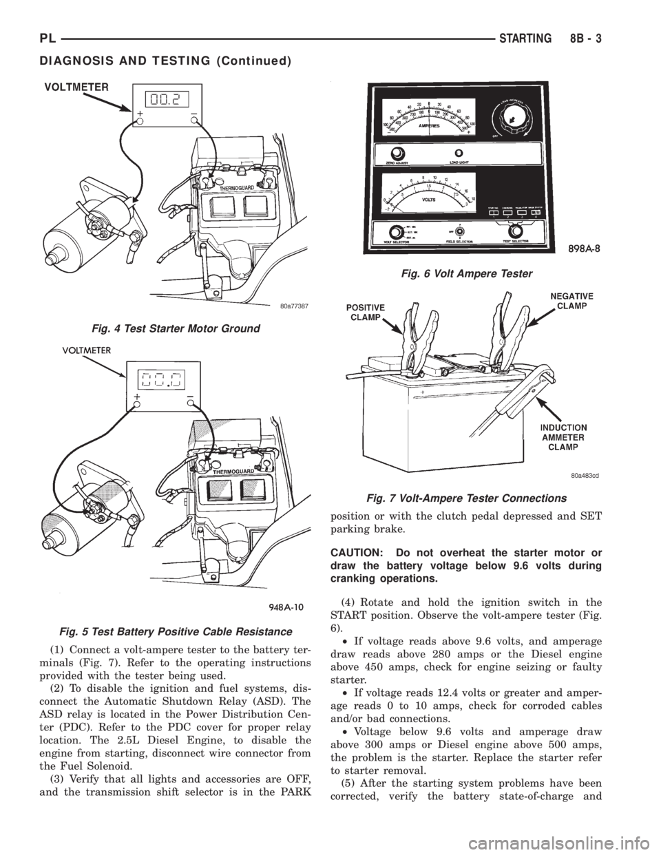
(1) Connect a volt-ampere tester to the battery ter-
minals (Fig. 7). Refer to the operating instructions
provided with the tester being used.
(2) To disable the ignition and fuel systems, dis-
connect the Automatic Shutdown Relay (ASD). The
ASD relay is located in the Power Distribution Cen-
ter (PDC). Refer to the PDC cover for proper relay
location. The 2.5L Diesel Engine, to disable the
engine from starting, disconnect wire connector from
the Fuel Solenoid.
(3) Verify that all lights and accessories are OFF,
and the transmission shift selector is in the PARKposition or with the clutch pedal depressed and SET
parking brake.
CAUTION: Do not overheat the starter motor or
draw the battery voltage below 9.6 volts during
cranking operations.
(4) Rotate and hold the ignition switch in the
START position. Observe the volt-ampere tester (Fig.
6).
²If voltage reads above 9.6 volts, and amperage
draw reads above 280 amps or the Diesel engine
above 450 amps, check for engine seizing or faulty
starter.
²If voltage reads 12.4 volts or greater and amper-
age reads 0 to 10 amps, check for corroded cables
and/or bad connections.
²Voltage below 9.6 volts and amperage draw
above 300 amps or Diesel engine above 500 amps,
the problem is the starter. Replace the starter refer
to starter removal.
(5) After the starting system problems have been
corrected, verify the battery state-of-charge and
Fig. 6 Volt Ampere Tester
Fig. 7 Volt-Ampere Tester Connections
Fig. 4 Test Starter Motor Ground
Fig. 5 Test Battery Positive Cable Resistance
PLSTARTING 8B - 3
DIAGNOSIS AND TESTING (Continued)