battery replacement DODGE NEON 1999 Service Repair Manual
[x] Cancel search | Manufacturer: DODGE, Model Year: 1999, Model line: NEON, Model: DODGE NEON 1999Pages: 1200, PDF Size: 35.29 MB
Page 89 of 1200
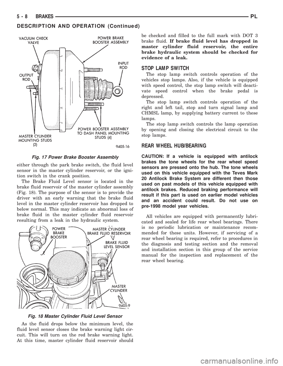
either through the park brake switch, the fluid level
sensor in the master cylinder reservoir, or the igni-
tion switch in the crank position.
The Brake Fluid Level sensor is located in the
brake fluid reservoir of the master cylinder assembly
(Fig. 18). The purpose of the sensor is to provide the
driver with an early warning that the brake fluid
level in the master cylinder reservoir has dropped to
below normal. This may indicate an abnormal loss of
brake fluid in the master cylinder fluid reservoir
resulting from a leak in the hydraulic system.
As the fluid drops below the minimum level, the
fluid level sensor closes the brake warning light cir-
cuit. This will turn on the red brake warning light.
At this time, master cylinder fluid reservoir shouldbe checked and filled to the full mark with DOT 3
brake fluid.If brake fluid level has dropped in
master cylinder fluid reservoir, the entire
brake hydraulic system should be checked for
evidence of a leak.
STOP LAMP SWITCH
The stop lamp switch controls operation of the
vehicles stop lamps. Also, if the vehicle is equipped
with speed control, the stop lamp switch will deacti-
vate speed control when the brake pedal is
depressed.
The stop lamp switch controls operation of the
right and left tail, stop and turn signal lamp and
CHMSL lamp, by supplying battery current to these
lamps.
The stop lamp switch controls the lamp operation
by opening and closing the electrical circuit to the
stop lamps.
REAR WHEEL HUB/BEARING
CAUTION: If a vehicle is equipped with antilock
brakes the tone wheels for the rear wheel speed
sensors are pressed onto the hub. The tone wheels
used on this vehicle equipped with the Teves Mark
20 Antilock Brake System are different then those
used on past models of this vehicle equipped with
antilock brakes. Reduced braking performance will
result if this part is used on earlier model vehicles
and an accident could result. Do not use on
pre-1998 model year vehicles.
All vehicles are equipped with permanently lubri-
cated and sealed for life rear wheel bearings. There
is no periodic lubrication or maintenance recom-
mended for these units. However, if servicing of a
rear wheel bearing is required, refer to procedures in
the diagnosis and testing section and the removal
and installation section in this group of the service
manual for the inspection and replacement of the
rear wheel bearing.Fig. 17 Power Brake Booster Assembly
Fig. 18 Master Cylinder Fluid Level Sensor
5 - 8 BRAKESPL
DESCRIPTION AND OPERATION (Continued)
Page 154 of 1200
ABS FUSES
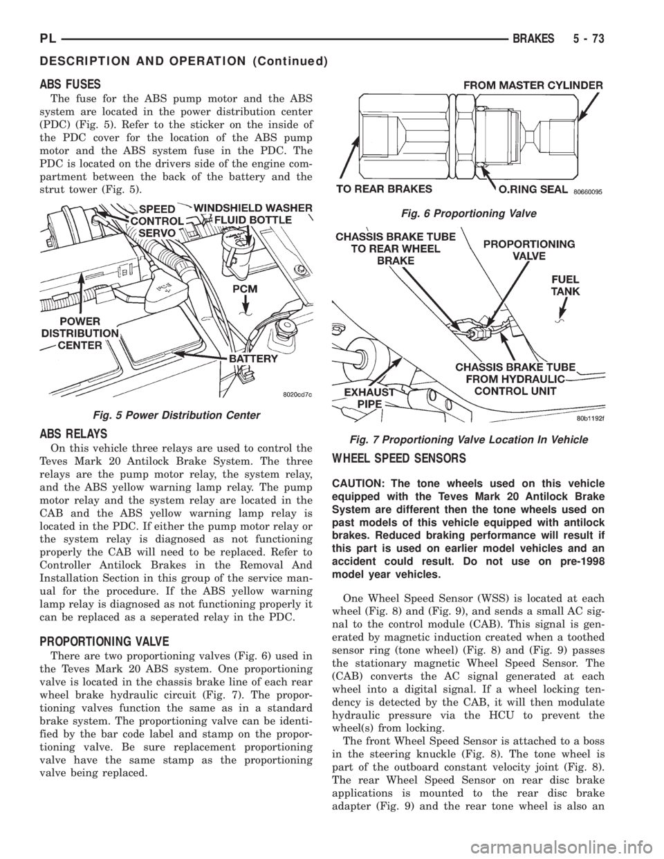
The fuse for the ABS pump motor and the ABS
system are located in the power distribution center
(PDC) (Fig. 5). Refer to the sticker on the inside of
the PDC cover for the location of the ABS pump
motor and the ABS system fuse in the PDC. The
PDC is located on the drivers side of the engine com-
partment between the back of the battery and the
strut tower (Fig. 5).
ABS RELAYS
On this vehicle three relays are used to control the
Teves Mark 20 Antilock Brake System. The three
relays are the pump motor relay, the system relay,
and the ABS yellow warning lamp relay. The pump
motor relay and the system relay are located in the
CAB and the ABS yellow warning lamp relay is
located in the PDC. If either the pump motor relay or
the system relay is diagnosed as not functioning
properly the CAB will need to be replaced. Refer to
Controller Antilock Brakes in the Removal And
Installation Section in this group of the service man-
ual for the procedure. If the ABS yellow warning
lamp relay is diagnosed as not functioning properly it
can be replaced as a seperated relay in the PDC.
PROPORTIONING VALVE
There are two proportioning valves (Fig. 6) used in
the Teves Mark 20 ABS system. One proportioning
valve is located in the chassis brake line of each rear
wheel brake hydraulic circuit (Fig. 7). The propor-
tioning valves function the same as in a standard
brake system. The proportioning valve can be identi-
fied by the bar code label and stamp on the propor-
tioning valve. Be sure replacement proportioning
valve have the same stamp as the proportioning
valve being replaced.
WHEEL SPEED SENSORS
CAUTION: The tone wheels used on this vehicle
equipped with the Teves Mark 20 Antilock Brake
System are different then the tone wheels used on
past models of this vehicle equipped with antilock
brakes. Reduced braking performance will result if
this part is used on earlier model vehicles and an
accident could result. Do not use on pre-1998
model year vehicles.
One Wheel Speed Sensor (WSS) is located at each
wheel (Fig. 8) and (Fig. 9), and sends a small AC sig-
nal to the control module (CAB). This signal is gen-
erated by magnetic induction created when a toothed
sensor ring (tone wheel) (Fig. 8) and (Fig. 9) passes
the stationary magnetic Wheel Speed Sensor. The
(CAB) converts the AC signal generated at each
wheel into a digital signal. If a wheel locking ten-
dency is detected by the CAB, it will then modulate
hydraulic pressure via the HCU to prevent the
wheel(s) from locking.
The front Wheel Speed Sensor is attached to a boss
in the steering knuckle (Fig. 8). The tone wheel is
part of the outboard constant velocity joint (Fig. 8).
The rear Wheel Speed Sensor on rear disc brake
applications is mounted to the rear disc brake
adapter (Fig. 9) and the rear tone wheel is also an
Fig. 5 Power Distribution Center
Fig. 6 Proportioning Valve
Fig. 7 Proportioning Valve Location In Vehicle
PLBRAKES 5 - 73
DESCRIPTION AND OPERATION (Continued)
Page 163 of 1200
CAUTION: Certain components of the ABS System
are not intended to be serviced individually.
Attempting to remove or disconnect certain system
components may result in improper system opera-
tion. Only those components with approved
removal and installation procedures in this manual
should be serviced.
CAUTION: Brake fluid will damage painted sur-
faces. If brake fluid is spilled on any painted sur-
faces, wash off with water immediately.
CAUTION: When performing any service procedure
on a vehicle equipped with ABS do not apply a 12
volt power source to the ground circuit of the pump
motor in the HCU. Doing this will damage the pump
motor and will require replacement of the entire
HCU.
The following are general cautions which should be
observed when servicing the ABS system and/or
other vehicle systems. Failure to observe these pre-
cautions may result in ABS System component dam-
age.
If welding work is to be performed on the vehicle,
using an electric arc welder, the CAB connector
should be disconnected during the welding operation.
The CAB 25 way connector connector should never
be connected or disconnected with the ignition switch
in the ON position.
Many components of the ABS System are not ser-
viceable and must be replaced as an assembly. Do not
disassemble any component which is not designed to
be serviced.
ABS HYDRAULIC CONTROL UNIT
REMOVE
(1) Disconnect negative (ground) cable from the
battery and isolate cable.
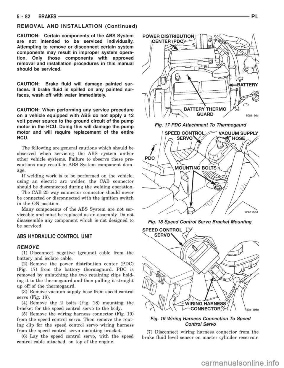
(2) Remove the power distribution center (PDC)
(Fig. 17) from the battery thermogaurd. PDC is
removed by unlatching the two retaining clips hold-
ing it to the thermogaurd and then pulling it straight
up off of the thermogaurd.
(3) Remove vacuum supply hose from speed control
servo (Fig. 18).
(4) Remove the 2 bolts (Fig. 18) mounting the
bracket for the speed control servo to the body.
(5) Remove the wiring harness connector (Fig. 19)
from the speed control servo. Then remove the rout-
ing clip for the speed control servo wiring harness
from the speed control servo mounting bracket.
(6) Lay the speed control servo, with the speed
control cable attached, on top of the engine.(7) Disconnect wiring harness connector from the
brake fluid level sensor on master cylinder reservoir.
Fig. 17 PDC Attachment To Thermogaurd
Fig. 18 Speed Control Servo Bracket Mounting
Fig. 19 Wiring Harness Connection To Speed
Control Servo
5 - 82 BRAKESPL
REMOVAL AND INSTALLATION (Continued)
Page 173 of 1200
The clutch cable has a unique self-adjuster mecha-
nism built into the cable which compensates for
clutch disc wear. The cable requires no maintenance
or lubrication. There are no serviceable components
on the cable assembly.
The clutch pedal is connected to the cable through
a plastic spacer. The upper end of the clutch pedal
pivots in the pedal bracket on two nylon bushings
and a shaft. These bushings are greased at assembly
and do not require periodic lubrication.
CLUTCH DISC AND COVER APPLICATION
The 2.0 single overhead cam engine uses a 216 mm
(8.5 in.) clutch disc. The manual transaxle is avail-
able only with the 2.0 liter engine.
CLUTCH REPLACEMENT
The transaxle must be removed to service the
clutch disc, pressure plate, flywheel/drive plate,
and/or clutch release bearing and lever.
DESCRIPTION AND OPERATION
CLUTCH CABLE
The manual transaxle clutch release system has a
unique self-adjusting mechanism to compensate for
clutch disc wear. This adjuster mechanism is located
within the clutch cable assembly. The preload spring
maintains tension on the cable. This tension keeps
the clutch release bearing continuously loaded
against the fingers of the clutch cover assembly.
CLUTCH PEDAL POSITION SWITCH
The clutch pedal position switch functions as a
safety interlock device. It prevents possible engine
cranking with the clutch engaged.
The clutch pedal position switch is wired in series
between the starter relay coil and the ignition
switch.
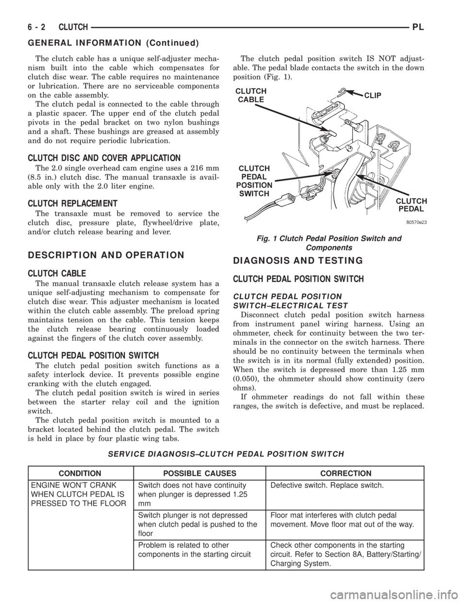
The clutch pedal position switch is mounted to a
bracket located behind the clutch pedal. The switch
is held in place by four plastic wing tabs.The clutch pedal position switch IS NOT adjust-
able. The pedal blade contacts the switch in the down
position (Fig. 1).
DIAGNOSIS AND TESTING
CLUTCH PEDAL POSITION SWITCH
CLUTCH PEDAL POSITION
SWITCH±ELECTRICAL TEST
Disconnect clutch pedal position switch harness
from instrument panel wiring harness. Using an
ohmmeter, check for continuity between the two ter-
minals in the connector on the switch harness. There
should be no continuity between the terminals when
the switch is in its normal (fully extended) position.
When the switch is depressed more than 1.25 mm
(0.050), the ohmmeter should show continuity (zero
ohms).
If ohmmeter readings do not fall within these
ranges, the switch is defective, and must be replaced.
SERVICE DIAGNOSIS±CLUTCH PEDAL POSITION SWITCH
CONDITION POSSIBLE CAUSES CORRECTION
ENGINE WON'T CRANK
WHEN CLUTCH PEDAL IS
PRESSED TO THE FLOORSwitch does not have continuity
when plunger is depressed 1.25
mmDefective switch. Replace switch.
Switch plunger is not depressed
when clutch pedal is pushed to the
floorFloor mat interferes with clutch pedal
movement. Move floor mat out of the way.
Problem is related to other
components in the starting circuitCheck other components in the starting
circuit. Refer to Section 8A, Battery/Starting/
Charging System.
Fig. 1 Clutch Pedal Position Switch and
Components
6 - 2 CLUTCHPL
GENERAL INFORMATION (Continued)
Page 237 of 1200
A battery temperature sensor located on the front
bumper beam is used to sense battery temperature.
This temperature data, along with data from moni-
tored line voltage, is used by the PCM to vary the
battery charging rate. This is done by cycling the
ground path to control the strength of the rotor mag-
netic field. The PCM then compensates and regulates
generator current output accordingly and to maintain
the proper voltage depending on battery tempera-
ture.
All vehicles are equipped with On-Board Diagnos-
tics (OBD). All OBD-sensed systems, including the
EVR (field control) circuitry, are monitored by the
PCM. Each monitored circuit is assigned a Diagnos-
tic Trouble Code (DTC). The PCM will store a DTC in
electronic memory for any failure it detects. See On-
Board Diagnostic System Test in this group for more
information.
GENERATOR
The generator is belt-driven by the engine. It is
serviced only as a complete assembly. If the genera-
tor fails for any reason, the entire assembly must be
replaced.
As the energized rotor begins to rotate within the
generator, the spinning magnetic field induces a cur-
rent into the windings of the stator coil. Once the
generator begins producing sufficient current, it also
provides the current needed to energize the rotor.
The Y type stator winding connections deliver the
induced AC current to 3 positive and 3 negative
diodes for rectification. From the diodes, rectified DC
current is delivered to the vehicle electrical system
through the generator, battery, and ground terminals.
Noise emitting from the generator may be caused
by:
²Worn, loose or defective bearings
²Loose or defective drive pulley
²Incorrect, worn, damaged or misadjusted drive
belt
²Loose mounting bolts
²Misaligned drive pulley
²Defective stator or diode
BATTERY TEMPERATURE SENSOR
The battery temperature sensor is used to deter-
mine the battery temperature. This temperature
data, along with data from monitored line voltage, is
used by the PCM to vary the battery charging rate.
System voltage will be higher at colder temperatures
and is gradually reduced at warmer temperatures.
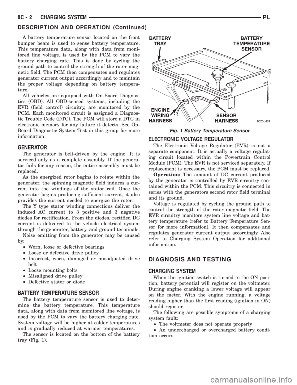
The sensor is located on the bottom of the battery
tray (Fig. 1).
ELECTRONIC VOLTAGE REGULATOR
The Electronic Voltage Regulator (EVR) is not a
separate component. It is actually a voltage regulat-
ing circuit located within the Powertrain Control
Module (PCM). The EVR is not serviced separately. If
replacement is necessary, the PCM must be replaced.
Operation:The amount of DC current produced
by the generator is controlled by EVR circuitry con-
tained within the PCM. This circuitry is connected in
series with the generators second rotor field terminal
and its ground.
Voltage is regulated by cycling the ground path to
control the strength of the rotor magnetic field. The
EVR circuitry monitors system line voltage and bat-
tery temperature (refer to Battery Temperature Sen-
sor for more information). It then compensates and
regulates generator current output accordingly. Also
refer to Charging System Operation for additional
information.
DIAGNOSIS AND TESTING
CHARGING SYSTEM
When the ignition switch is turned to the ON posi-
tion, battery potential will register on the voltmeter.
During engine cranking a lower voltage will appear
on the meter. With the engine running, a voltage
reading higher than the first reading (ignition in ON)
should register.
The following are possible symptoms of a charging
system fault:
²The voltmeter does not operate properly
²An undercharged or overcharged battery condi-
tion occurs.
Fig. 1 Battery Temperature Sensor
8C - 2 CHARGING SYSTEMPL
DESCRIPTION AND OPERATION (Continued)
Page 315 of 1200
DIAGNOSIS AND TESTING
WINDSHIELD WIPER CONDITION
WARNING: ON VEHICLES EQUIPPED WITH AIR-
BAGS, SEE GROUP 8M, RESTRAINT SYSTEMS FOR
STEERING WHEEL OR COLUMN REMOVAL PROCE-
DURES.
The following is a list of general wiper motor sys-
tem problems, the tests that are to be performed to
locate the faulty part, and the corrective action to be
taken.
Whatever the problem, disconnect motor wire har-
ness and clean the terminals, then connect motor
wire harness and test.
MOTOR WILL NOT OPERATE IN SOME OR ALL
SWITCH POSITIONS
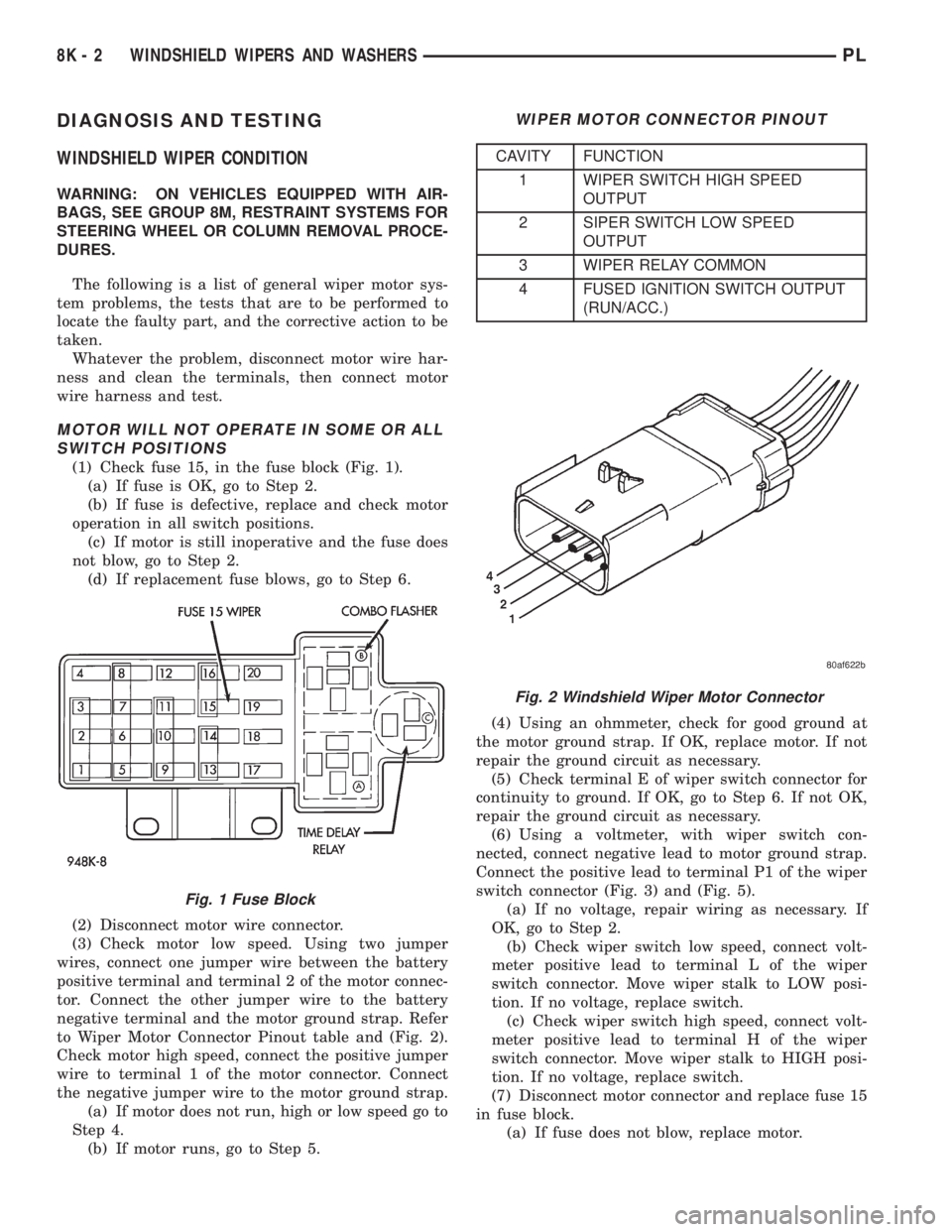
(1) Check fuse 15, in the fuse block (Fig. 1).
(a) If fuse is OK, go to Step 2.
(b) If fuse is defective, replace and check motor
operation in all switch positions.
(c) If motor is still inoperative and the fuse does
not blow, go to Step 2.
(d) If replacement fuse blows, go to Step 6.
(2) Disconnect motor wire connector.
(3) Check motor low speed. Using two jumper
wires, connect one jumper wire between the battery
positive terminal and terminal 2 of the motor connec-
tor. Connect the other jumper wire to the battery
negative terminal and the motor ground strap. Refer
to Wiper Motor Connector Pinout table and (Fig. 2).
Check motor high speed, connect the positive jumper
wire to terminal 1 of the motor connector. Connect
the negative jumper wire to the motor ground strap.
(a) If motor does not run, high or low speed go to
Step 4.
(b) If motor runs, go to Step 5.(4) Using an ohmmeter, check for good ground at
the motor ground strap. If OK, replace motor. If not
repair the ground circuit as necessary.
(5) Check terminal E of wiper switch connector for
continuity to ground. If OK, go to Step 6. If not OK,
repair the ground circuit as necessary.
(6) Using a voltmeter, with wiper switch con-
nected, connect negative lead to motor ground strap.
Connect the positive lead to terminal P1 of the wiper
switch connector (Fig. 3) and (Fig. 5).
(a) If no voltage, repair wiring as necessary. If
OK, go to Step 2.
(b) Check wiper switch low speed, connect volt-
meter positive lead to terminal L of the wiper
switch connector. Move wiper stalk to LOW posi-
tion. If no voltage, replace switch.
(c) Check wiper switch high speed, connect volt-
meter positive lead to terminal H of the wiper
switch connector. Move wiper stalk to HIGH posi-
tion. If no voltage, replace switch.
(7) Disconnect motor connector and replace fuse 15
in fuse block.
(a) If fuse does not blow, replace motor.
Fig. 1 Fuse Block
WIPER MOTOR CONNECTOR PINOUT
CAVITY FUNCTION
1 WIPER SWITCH HIGH SPEED
OUTPUT
2 SIPER SWITCH LOW SPEED
OUTPUT
3 WIPER RELAY COMMON
4 FUSED IGNITION SWITCH OUTPUT
(RUN/ACC.)
Fig. 2 Windshield Wiper Motor Connector
8K - 2 WINDSHIELD WIPERS AND WASHERSPL
Page 352 of 1200
RESTRAINT SYSTEM
CONTENTS
page page
GENERAL INFORMATION
WARNINGS AND PRECAUTIONS............ 1
DESCRIPTION AND OPERATION
AIRBAG CONTROL MODULE............... 1
CLOCKSPRING.......................... 2
DRIVER AND PASSENGER AIRBAG MODULE . . 2
DIAGNOSIS AND TESTING
AIRBAG SYSTEM TEST................... 3
SERVICE PROCEDURES
CLEANUP PROCEDURE................... 3HANDLING AIRBAG MODULE.............. 3
MAINTENANCE INSPECTION............... 4
REMOVAL AND INSTALLATION
AIRBAG CONTROL MODULE (ACM)......... 4
CLOCKSPRING.......................... 8
DRIVER AIRBAG MODULE................. 9
PASSENGER AIRBAG MODULE............. 9
STEERING WHEEL...................... 10
ADJUSTMENTS
CLOCKSPRING CENTERING PROCEDURE.... 11
GENERAL INFORMATION
WARNINGS AND PRECAUTIONS
WARNING: THIS SYSTEM IS A SENSITIVE, COM-
PLEX ELECTRO±MECHANICAL UNIT. DISCONNECT
AND ISOLATE THE BATTERY NEGATIVE CABLE
BEFORE BEGINNING AIRBAG SYSTEM COMPO-
NENT REMOVAL OR INSTALLATION PROCEDURES.
THIS WILL DISABLE THE AIRBAG SYSTEM. FAIL-
URE TO DISCONNECT THE BATTERY COULD
RESULT IN ACCIDENTAL AIRBAG DEPLOYMENT
AND POSSIBLE PERSONAL INJURY.
ALLOW SYSTEM CAPACITOR TO DISCHARGE
FOR TWO MINUTES BEFORE REMOVING AIRBAG
COMPONENTS.
DO NOT PLACE AN INTACT UNDEPLOYED AIR-
BAG FACE DOWN ON A SOLID SURFACE, THE AIR-
BAG WILL PROPEL INTO THE AIR IF
ACCIDENTALLY DEPLOYED AND COULD RESULT
IN PERSONAL INJURY. WHEN CARRYING OR HAN-
DLING AN UNDEPLOYED AIRBAG MODULE, THE
TRIM SIDE OF THE AIRBAG SHOULD BE POINTING
AWAY FROM THE BODY TO MINIMIZE POSSIBILITY
OF INJURY IF ACCIDENTAL DEPLOYMENT
OCCURS.
REPLACE AIRBAG SYSTEM COMPONENTS WITH
MOPARTREPLACEMENT PARTS. SUBSTITUTE
PARTS MAY APPEAR INTERCHANGEABLE, BUT
INTERNAL DIFFERENCES MAY RESULT IN INFE-
RIOR OCCUPANT PROTECTION.
WEAR SAFETY GLASSES, RUBBER GLOVES,
AND LONG SLEEVES CLOTHING WHEN CLEANING
POWDER RESIDUE FROM VEHICLE AFTER AIRBAG
DEPLOYMENT. SODIUM HYDROXIDE POWDER
RESIDUE EMITTED FROM A DEPLOYED AIRBAGCAN CAUSE SKIN IRRITATION. FLUSH AFFECTED
AREA WITH COOL WATER IF IRRITATION IS EXPE-
RIENCED. IF NASAL OR THROAT IRRITATION IS
EXPERIENCED, EXIT THE VEHICLE FOR FRESH AIR
UNTIL THE IRRITATION CEASES. IF IRRITATION
CONTINUES, SEE A PHYSICIAN.
DO NOT USE A REPLACEMENT AIRBAG THAT IS
NOT IN THE ORIGINAL PACKAGING, IMPROPER
DEPLOYMENT AND PERSONAL INJURY CAN
RESULT.
THE FACTORY INSTALLED FASTENERS,
SCREWS AND BOLTS USED TO FASTEN AIRBAG
COMPONENTS, ARE SPECIFICALLY DESIGNED
FOR THE AIRBAG SYSTEM. DO NOT USE SUBSTI-
TUTE FASTENERS, USE ONLY ORIGINAL EQUIP-
MENT FASTENERS LISTED IN THE PARTS
CATALOG WHEN FASTENER REPLACEMENT IS
REQUIRED.
NOTE: Airbags should be stored in a cool dry loca-
tion away from excessive heat and static electrical
activity with the fabric airbag facing UP, or a prema-
ture deployment can result.
If the Driver/Passenger Airbag Module is defective
and not deployed, refer to Chrysler Corporation cur-
rent return list for proper handling procedures.
DESCRIPTION AND OPERATION
AIRBAG CONTROL MODULE
The Airbag Control Module (ACM) contains the
safing sensor and energy reserve capacitor. The saf-
ing sensor is located inside the ACM. The module is
mounted on the tunnel/floor pan between the gear
PLRESTRAINT SYSTEM 8M - 1
Page 366 of 1200
Instrument Panel and Systems for removal proce-
dures.
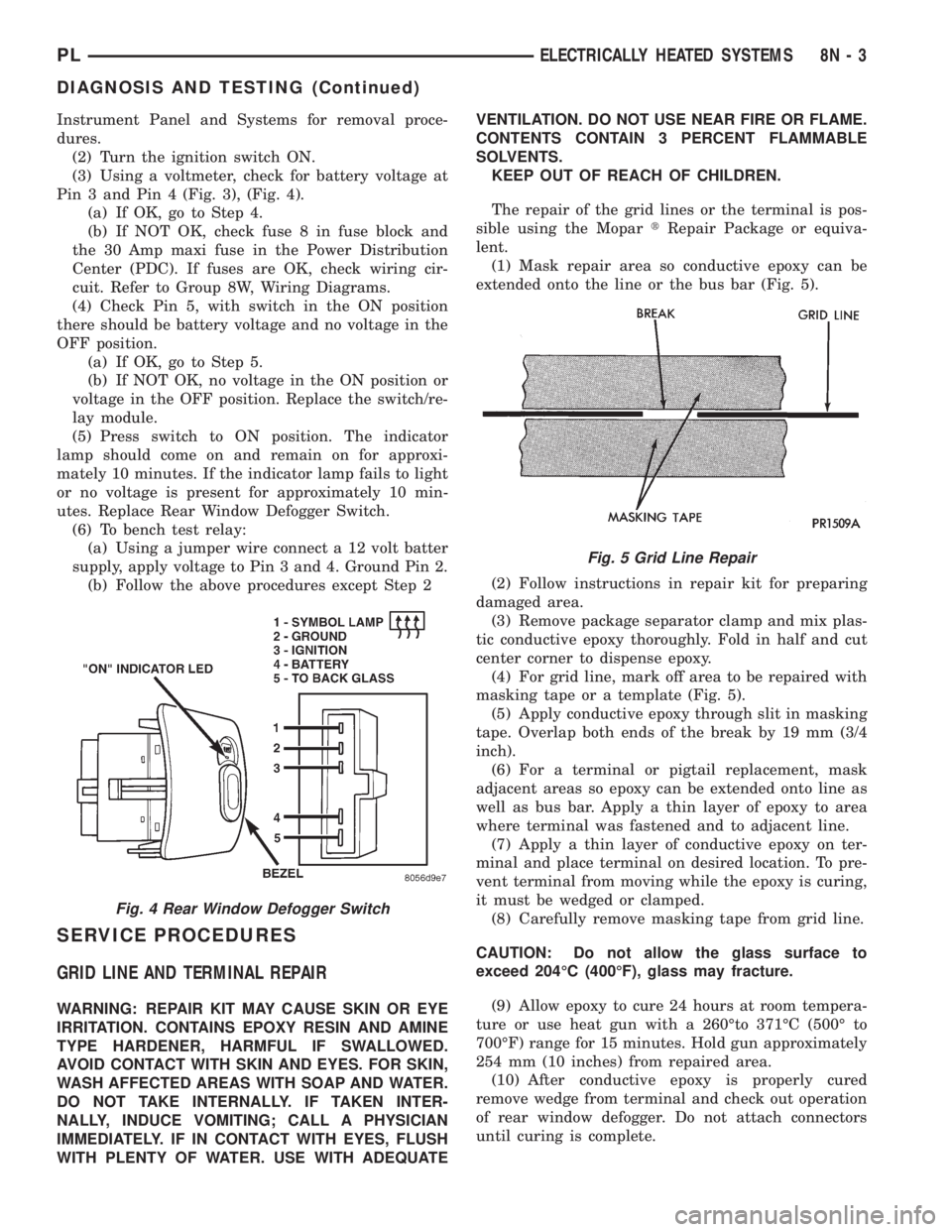
(2) Turn the ignition switch ON.
(3) Using a voltmeter, check for battery voltage at
Pin 3 and Pin 4 (Fig. 3), (Fig. 4).
(a) If OK, go to Step 4.
(b) If NOT OK, check fuse 8 in fuse block and
the 30 Amp maxi fuse in the Power Distribution
Center (PDC). If fuses are OK, check wiring cir-
cuit. Refer to Group 8W, Wiring Diagrams.
(4) Check Pin 5, with switch in the ON position
there should be battery voltage and no voltage in the
OFF position.
(a) If OK, go to Step 5.
(b) If NOT OK, no voltage in the ON position or
voltage in the OFF position. Replace the switch/re-
lay module.
(5) Press switch to ON position. The indicator
lamp should come on and remain on for approxi-
mately 10 minutes. If the indicator lamp fails to light
or no voltage is present for approximately 10 min-
utes. Replace Rear Window Defogger Switch.
(6) To bench test relay:
(a) Using a jumper wire connect a 12 volt batter
supply, apply voltage to Pin 3 and 4. Ground Pin 2.
(b) Follow the above procedures except Step 2
SERVICE PROCEDURES
GRID LINE AND TERMINAL REPAIR
WARNING: REPAIR KIT MAY CAUSE SKIN OR EYE
IRRITATION. CONTAINS EPOXY RESIN AND AMINE
TYPE HARDENER, HARMFUL IF SWALLOWED.
AVOID CONTACT WITH SKIN AND EYES. FOR SKIN,
WASH AFFECTED AREAS WITH SOAP AND WATER.
DO NOT TAKE INTERNALLY. IF TAKEN INTER-
NALLY, INDUCE VOMITING; CALL A PHYSICIAN
IMMEDIATELY. IF IN CONTACT WITH EYES, FLUSH
WITH PLENTY OF WATER. USE WITH ADEQUATEVENTILATION. DO NOT USE NEAR FIRE OR FLAME.
CONTENTS CONTAIN 3 PERCENT FLAMMABLE
SOLVENTS.
KEEP OUT OF REACH OF CHILDREN.
The repair of the grid lines or the terminal is pos-
sible using the MopartRepair Package or equiva-
lent.
(1) Mask repair area so conductive epoxy can be
extended onto the line or the bus bar (Fig. 5).
(2) Follow instructions in repair kit for preparing
damaged area.
(3) Remove package separator clamp and mix plas-
tic conductive epoxy thoroughly. Fold in half and cut
center corner to dispense epoxy.
(4) For grid line, mark off area to be repaired with
masking tape or a template (Fig. 5).
(5) Apply conductive epoxy through slit in masking
tape. Overlap both ends of the break by 19 mm (3/4
inch).
(6) For a terminal or pigtail replacement, mask
adjacent areas so epoxy can be extended onto line as
well as bus bar. Apply a thin layer of epoxy to area
where terminal was fastened and to adjacent line.
(7) Apply a thin layer of conductive epoxy on ter-
minal and place terminal on desired location. To pre-
vent terminal from moving while the epoxy is curing,
it must be wedged or clamped.
(8) Carefully remove masking tape from grid line.
CAUTION: Do not allow the glass surface to
exceed 204ÉC (400ÉF), glass may fracture.
(9) Allow epoxy to cure 24 hours at room tempera-
ture or use heat gun with a 260Éto 371ÉC (500É to
700ÉF) range for 15 minutes. Hold gun approximately
254 mm (10 inches) from repaired area.
(10) After conductive epoxy is properly cured
remove wedge from terminal and check out operation
of rear window defogger. Do not attach connectors
until curing is complete.
Fig. 4 Rear Window Defogger Switch
Fig. 5 Grid Line Repair
PLELECTRICALLY HEATED SYSTEMS 8N - 3
DIAGNOSIS AND TESTING (Continued)
Page 405 of 1200
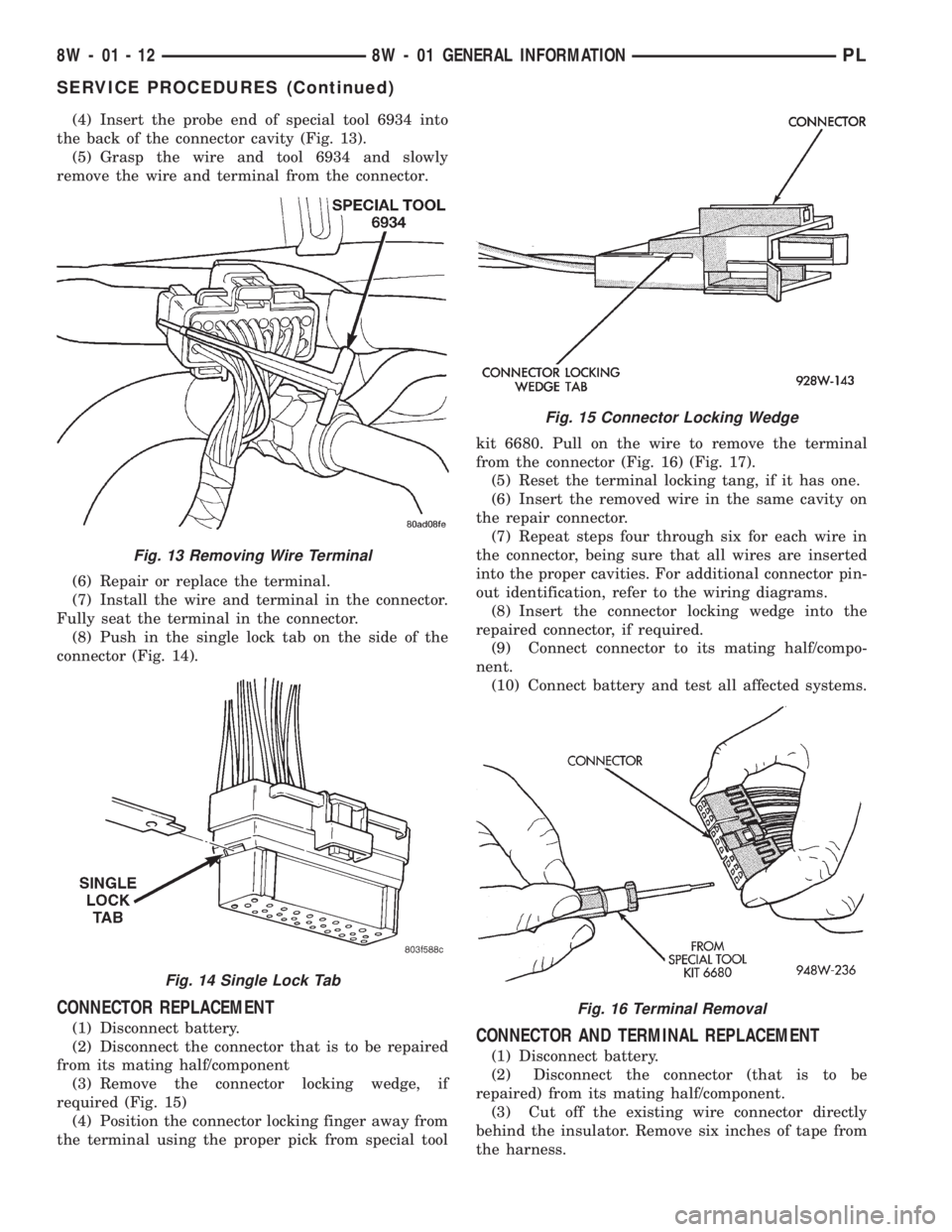
(4) Insert the probe end of special tool 6934 into
the back of the connector cavity (Fig. 13).
(5) Grasp the wire and tool 6934 and slowly
remove the wire and terminal from the connector.
(6) Repair or replace the terminal.
(7) Install the wire and terminal in the connector.
Fully seat the terminal in the connector.
(8) Push in the single lock tab on the side of the
connector (Fig. 14).
CONNECTOR REPLACEMENT
(1) Disconnect battery.
(2) Disconnect the connector that is to be repaired
from its mating half/component
(3) Remove the connector locking wedge, if
required (Fig. 15)
(4) Position the connector locking finger away from
the terminal using the proper pick from special toolkit 6680. Pull on the wire to remove the terminal
from the connector (Fig. 16) (Fig. 17).
(5) Reset the terminal locking tang, if it has one.
(6) Insert the removed wire in the same cavity on
the repair connector.
(7) Repeat steps four through six for each wire in
the connector, being sure that all wires are inserted
into the proper cavities. For additional connector pin-
out identification, refer to the wiring diagrams.
(8) Insert the connector locking wedge into the
repaired connector, if required.
(9) Connect connector to its mating half/compo-
nent.
(10) Connect battery and test all affected systems.CONNECTOR AND TERMINAL REPLACEMENT
(1) Disconnect battery.
(2) Disconnect the connector (that is to be
repaired) from its mating half/component.
(3) Cut off the existing wire connector directly
behind the insulator. Remove six inches of tape from
the harness.
Fig. 13 Removing Wire Terminal
Fig. 14 Single Lock Tab
Fig. 15 Connector Locking Wedge
Fig. 16 Terminal Removal
8W - 01 - 12 8W - 01 GENERAL INFORMATIONPL
SERVICE PROCEDURES (Continued)
Page 406 of 1200
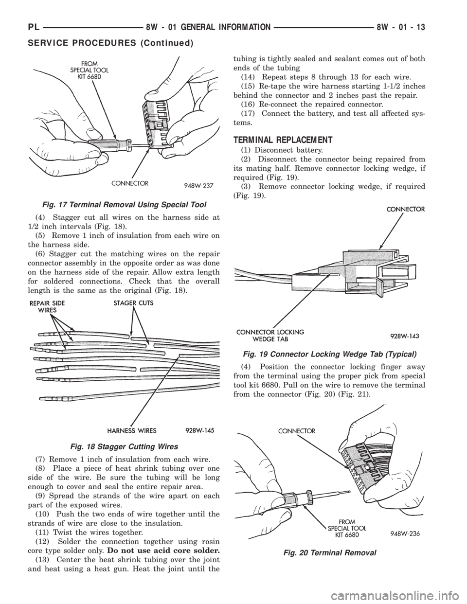
(4) Stagger cut all wires on the harness side at
1/2 inch intervals (Fig. 18).
(5) Remove 1 inch of insulation from each wire on
the harness side.
(6) Stagger cut the matching wires on the repair
connector assembly in the opposite order as was done
on the harness side of the repair. Allow extra length
for soldered connections. Check that the overall
length is the same as the original (Fig. 18).
(7) Remove 1 inch of insulation from each wire.
(8) Place a piece of heat shrink tubing over one
side of the wire. Be sure the tubing will be long
enough to cover and seal the entire repair area.
(9) Spread the strands of the wire apart on each
part of the exposed wires.
(10) Push the two ends of wire together until the
strands of wire are close to the insulation.
(11) Twist the wires together.
(12) Solder the connection together using rosin
core type solder only.Do not use acid core solder.
(13) Center the heat shrink tubing over the joint
and heat using a heat gun. Heat the joint until thetubing is tightly sealed and sealant comes out of both
ends of the tubing
(14) Repeat steps 8 through 13 for each wire.
(15) Re-tape the wire harness starting 1-1/2 inches
behind the connector and 2 inches past the repair.
(16) Re-connect the repaired connector.
(17) Connect the battery, and test all affected sys-
tems.
TERMINAL REPLACEMENT
(1) Disconnect battery.
(2) Disconnect the connector being repaired from
its mating half. Remove connector locking wedge, if
required (Fig. 19).
(3) Remove connector locking wedge, if required
(Fig. 19).
(4) Position the connector locking finger away
from the terminal using the proper pick from special
tool kit 6680. Pull on the wire to remove the terminal
from the connector (Fig. 20) (Fig. 21).
Fig. 17 Terminal Removal Using Special Tool
Fig. 18 Stagger Cutting Wires
Fig. 19 Connector Locking Wedge Tab (Typical)
Fig. 20 Terminal Removal
PL8W - 01 GENERAL INFORMATION 8W - 01 - 13
SERVICE PROCEDURES (Continued)