drain bolt DODGE NEON 1999 Service Repair Manual
[x] Cancel search | Manufacturer: DODGE, Model Year: 1999, Model line: NEON, Model: DODGE NEON 1999Pages: 1200, PDF Size: 35.29 MB
Page 210 of 1200
COOLING SYSTEMÐREFILLING
First clean system to remove old glycol, see Cooling
System Cleaning.
Fill system using antifreeze described in Coolant
section. Fill 50 percent of capacity with 100 percent
glycol. Then complete filling system with water.
Continue filling system until full, this provides bet-
ter heater performance.Be careful not to spill
coolant on drive belts or the generator.
Fill coolant reserve system to at least the FULL
mark with 50/50 solution. It may be necessary to add
coolant to the reserve tank after three or four warm-
up/cool down cycles to maintain coolant level between
the FULL and ADD marks; if any trapped air was
removed from the system.
REMOVAL AND INSTALLATION
WATER PUMP
REMOVAL
(1) Raise vehicle on a hoist. Remove right inner
splash shield.
(2) Remove accessory drive belts and power steer-
ing pump. Refer to Accessory Drive Belt service in
this section.
(3) Drain cooling system. Refer to Cooling System
Draining in this section.
(4) Support engine from the bottom and remove
right engine mount.
(5) Remove power steering pump bracket bolts and
set pump and bracket assembly aside. Power steering
lines do not need to be disconnected.
(6) Remove right engine mount bracket.
(7) Remove timing belt and timing belt tensioner.
Refer to Group 9, Engine for procedure.
(8) Remove camshaft sprockets and inner timing
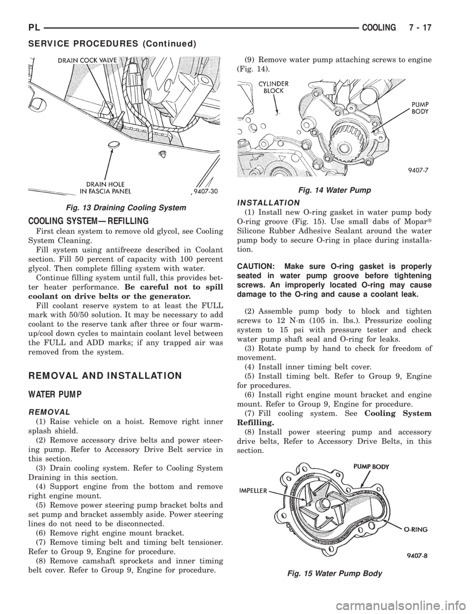
belt cover. Refer to Group 9, Engine for procedure.(9) Remove water pump attaching screws to engine
(Fig. 14).
INSTALLATION
(1) Install new O-ring gasket in water pump body
O-ring groove (Fig. 15). Use small dabs of Mopart
Silicone Rubber Adhesive Sealant around the water
pump body to secure O-ring in place during installa-
tion.
CAUTION: Make sure O-ring gasket is properly
seated in water pump groove before tightening
screws. An improperly located O-ring may cause
damage to the O-ring and cause a coolant leak.
(2) Assemble pump body to block and tighten
screws to 12 N´m (105 in. lbs.). Pressurize cooling
system to 15 psi with pressure tester and check
water pump shaft seal and O-ring for leaks.
(3) Rotate pump by hand to check for freedom of
movement.
(4) Install inner timing belt cover.
(5) Install timing belt. Refer to Group 9, Engine
for procedures.
(6) Install right engine mount bracket and engine
mount. Refer to Group 9, Engine for procedure.
(7) Fill cooling system. SeeCooling System
Refilling.
(8) Install power steering pump and accessory
drive belts, Refer to Accessory Drive Belts, in this
section.Fig. 13 Draining Cooling System
Fig. 14 Water Pump
Fig. 15 Water Pump Body
PLCOOLING 7 - 17
SERVICE PROCEDURES (Continued)
Page 211 of 1200
(9) Perform camshaft and crankshaft timing
relearn procedure as follows:
²Connect the DRB scan tool to the data link
(diagnostic) connector. This connector is located in
the passenger compartment; at the lower edge of
instrument panel; near the steering column.
²Turn the ignition switch on and access the ªmis-
cellaneousº screen.
²Select ªre-learn cam/crankº option and follow
directions on DRB screen.
WATER PUMP INLET TUBE
The inlet tube connects the water pump to the
radiator and heater core. This tube is sealed by a
O-ring and held in place by fasteners to the block.
REMOVAL
CAUTION: Do not use any sharp tools to remove
hoses from inlet tube. This may cause the tube to
leak.
(1) Drain cooling system. Refer to procedure out-
lined in this section.
(2) Remove upper radiator hose to access the hose
connections at the inlet tube.
(3) Remove lower radiator hose and heater hose
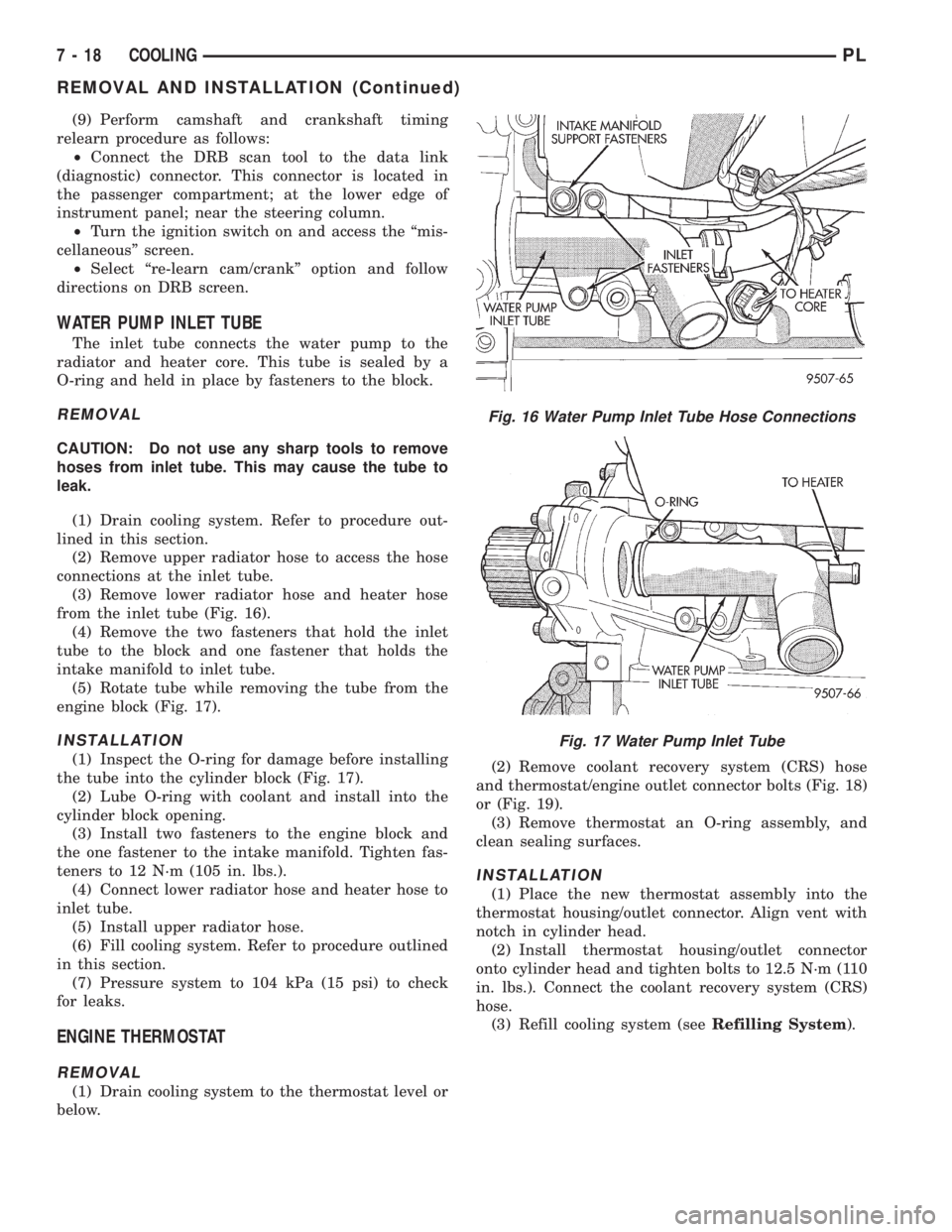
from the inlet tube (Fig. 16).
(4) Remove the two fasteners that hold the inlet
tube to the block and one fastener that holds the
intake manifold to inlet tube.
(5) Rotate tube while removing the tube from the
engine block (Fig. 17).
INSTALLATION
(1) Inspect the O-ring for damage before installing
the tube into the cylinder block (Fig. 17).
(2) Lube O-ring with coolant and install into the
cylinder block opening.
(3) Install two fasteners to the engine block and
the one fastener to the intake manifold. Tighten fas-
teners to 12 N´m (105 in. lbs.).
(4) Connect lower radiator hose and heater hose to
inlet tube.
(5) Install upper radiator hose.
(6) Fill cooling system. Refer to procedure outlined
in this section.
(7) Pressure system to 104 kPa (15 psi) to check
for leaks.
ENGINE THERMOSTAT
REMOVAL
(1) Drain cooling system to the thermostat level or
below.(2) Remove coolant recovery system (CRS) hose
and thermostat/engine outlet connector bolts (Fig. 18)
or (Fig. 19).
(3) Remove thermostat an O-ring assembly, and
clean sealing surfaces.
INSTALLATION
(1) Place the new thermostat assembly into the
thermostat housing/outlet connector. Align vent with
notch in cylinder head.
(2) Install thermostat housing/outlet connector
onto cylinder head and tighten bolts to 12.5 N´m (110
in. lbs.). Connect the coolant recovery system (CRS)
hose.
(3) Refill cooling system (seeRefilling System).
Fig. 16 Water Pump Inlet Tube Hose Connections
Fig. 17 Water Pump Inlet Tube
7 - 18 COOLINGPL
REMOVAL AND INSTALLATION (Continued)
Page 214 of 1200
must be replaced withonlythe recommended part
for adequate strength, performance and safety.
(1) To remove fan from motor shaft, bench support
the motor and motor shaft, while removing the fan
retaining clip, so that the shaft and motor will not be
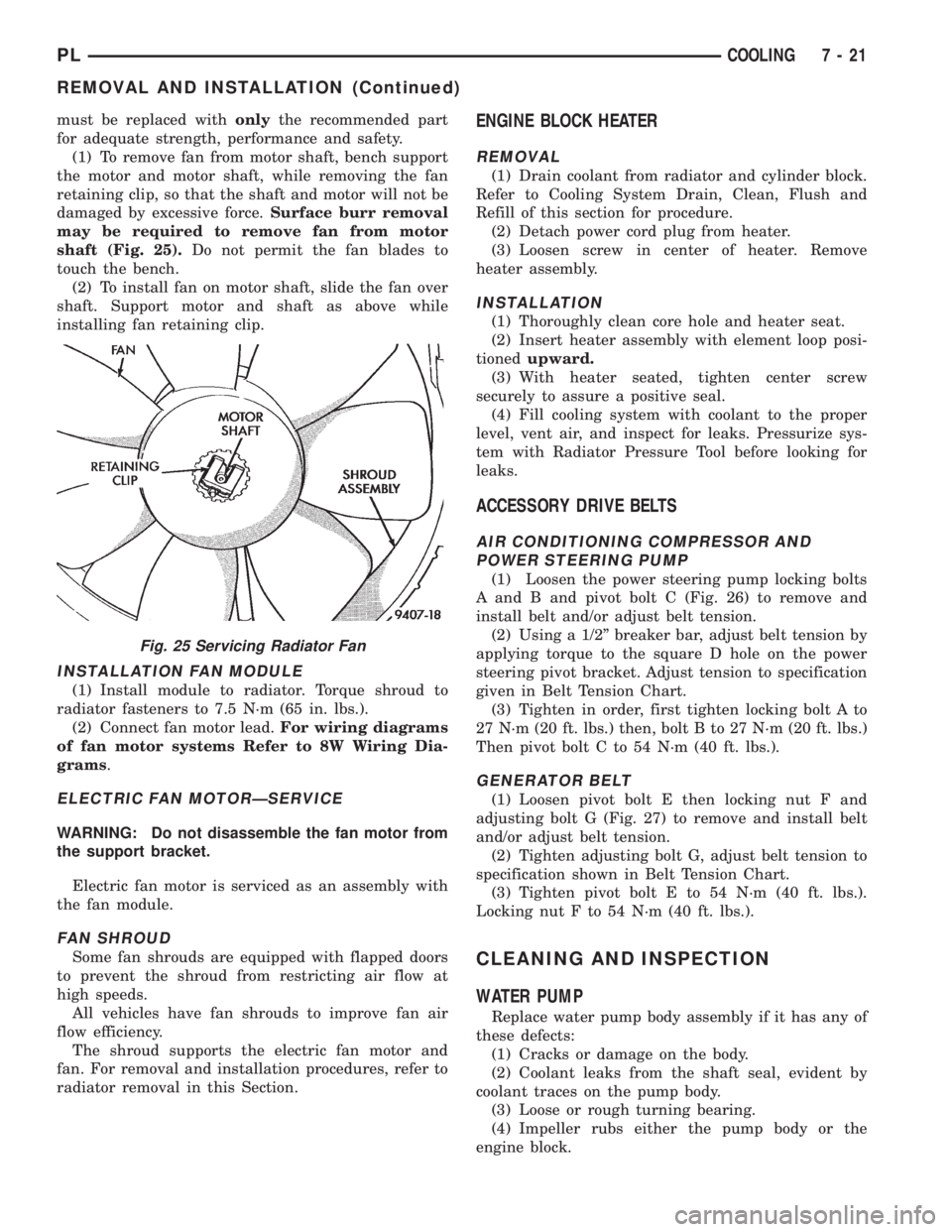
damaged by excessive force.Surface burr removal
may be required to remove fan from motor
shaft (Fig. 25).Do not permit the fan blades to
touch the bench.
(2) To install fan on motor shaft, slide the fan over
shaft. Support motor and shaft as above while
installing fan retaining clip.
INSTALLATION FAN MODULE
(1) Install module to radiator. Torque shroud to
radiator fasteners to 7.5 N´m (65 in. lbs.).
(2) Connect fan motor lead.For wiring diagrams
of fan motor systems Refer to 8W Wiring Dia-
grams.
ELECTRIC FAN MOTORÐSERVICE
WARNING: Do not disassemble the fan motor from
the support bracket.
Electric fan motor is serviced as an assembly with
the fan module.
FAN SHROUD
Some fan shrouds are equipped with flapped doors
to prevent the shroud from restricting air flow at
high speeds.
All vehicles have fan shrouds to improve fan air
flow efficiency.
The shroud supports the electric fan motor and
fan. For removal and installation procedures, refer to
radiator removal in this Section.
ENGINE BLOCK HEATER
REMOVAL
(1) Drain coolant from radiator and cylinder block.
Refer to Cooling System Drain, Clean, Flush and
Refill of this section for procedure.
(2) Detach power cord plug from heater.
(3) Loosen screw in center of heater. Remove
heater assembly.
INSTALLATION
(1) Thoroughly clean core hole and heater seat.
(2) Insert heater assembly with element loop posi-
tionedupward.
(3) With heater seated, tighten center screw
securely to assure a positive seal.
(4) Fill cooling system with coolant to the proper
level, vent air, and inspect for leaks. Pressurize sys-
tem with Radiator Pressure Tool before looking for
leaks.
ACCESSORY DRIVE BELTS
AIR CONDITIONING COMPRESSOR AND
POWER STEERING PUMP
(1) Loosen the power steering pump locking bolts
A and B and pivot bolt C (Fig. 26) to remove and
install belt and/or adjust belt tension.
(2) Using a 1/2º breaker bar, adjust belt tension by
applying torque to the square D hole on the power
steering pivot bracket. Adjust tension to specification
given in Belt Tension Chart.
(3) Tighten in order, first tighten locking bolt A to
27 N´m (20 ft. lbs.) then, bolt B to 27 N´m (20 ft. lbs.)
Then pivot bolt C to 54 N´m (40 ft. lbs.).
GENERATOR BELT
(1) Loosen pivot bolt E then locking nut F and
adjusting bolt G (Fig. 27) to remove and install belt
and/or adjust belt tension.
(2) Tighten adjusting bolt G, adjust belt tension to
specification shown in Belt Tension Chart.
(3) Tighten pivot bolt E to 54 N´m (40 ft. lbs.).
Locking nut F to 54 N´m (40 ft. lbs.).
CLEANING AND INSPECTION
WATER PUMP
Replace water pump body assembly if it has any of
these defects:
(1) Cracks or damage on the body.
(2) Coolant leaks from the shaft seal, evident by
coolant traces on the pump body.
(3) Loose or rough turning bearing.
(4) Impeller rubs either the pump body or the
engine block.
Fig. 25 Servicing Radiator Fan
PLCOOLING 7 - 21
REMOVAL AND INSTALLATION (Continued)
Page 732 of 1200
(3) Remove the power hop damper bracket, if nec-
essary.
(4) Reverse removal procedure for installation.
Tighten all bolts and nuts to 54 N´m (40 ft. lbs.)
STRUCTURAL COLLARÐ2.0L
REMOVAL
(1) Raise vehicle on hoist.
NOTE: To remove transaxle dust cover, the front
bending strut must be removed.
(2) Remove structural collar from oil pan to tran-
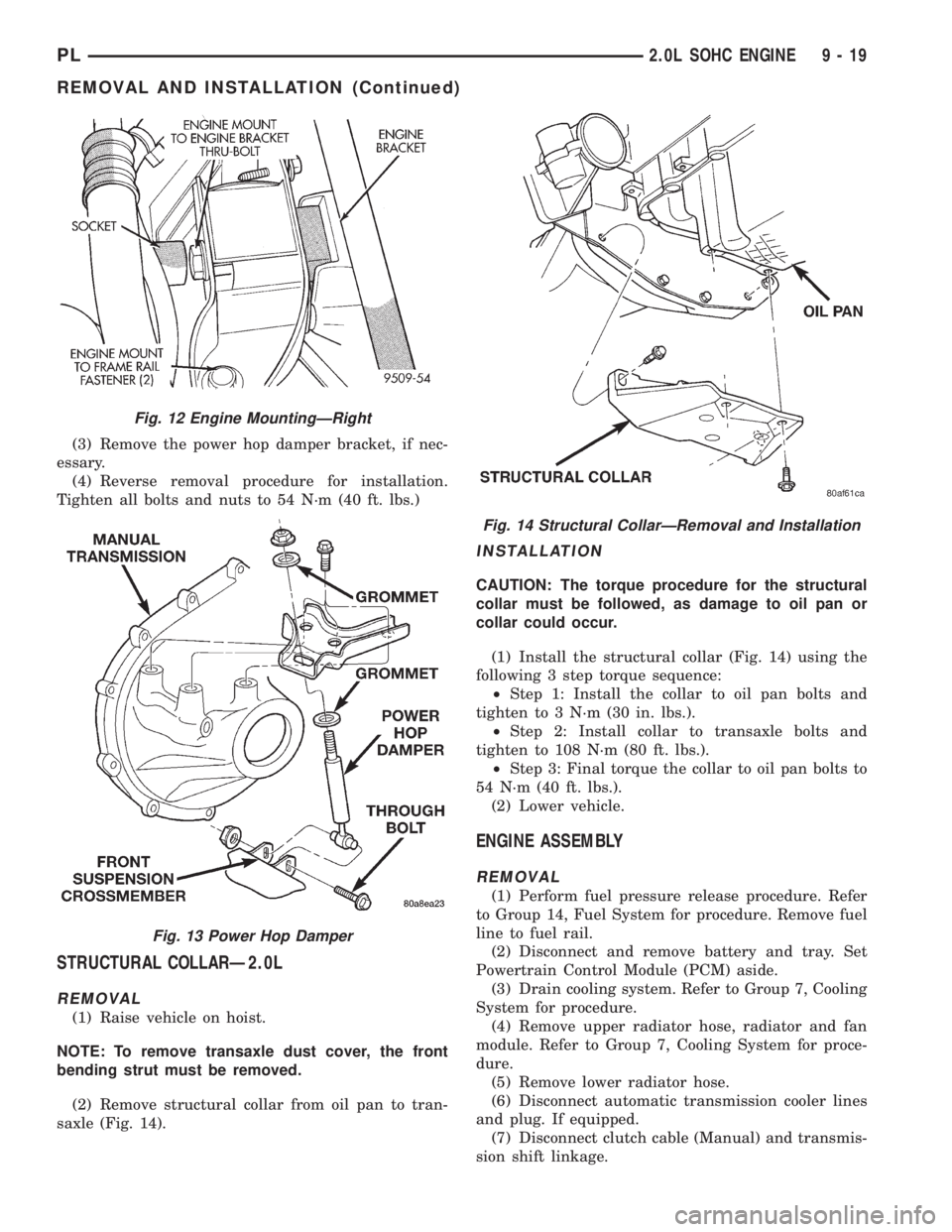
saxle (Fig. 14).
INSTALLATION
CAUTION: The torque procedure for the structural
collar must be followed, as damage to oil pan or
collar could occur.
(1) Install the structural collar (Fig. 14) using the
following 3 step torque sequence:
²Step 1: Install the collar to oil pan bolts and
tighten to 3 N´m (30 in. lbs.).
²Step 2: Install collar to transaxle bolts and
tighten to 108 N´m (80 ft. lbs.).
²Step 3: Final torque the collar to oil pan bolts to
54 N´m (40 ft. lbs.).
(2) Lower vehicle.
ENGINE ASSEMBLY
REMOVAL
(1) Perform fuel pressure release procedure. Refer
to Group 14, Fuel System for procedure. Remove fuel
line to fuel rail.
(2) Disconnect and remove battery and tray. Set
Powertrain Control Module (PCM) aside.
(3) Drain cooling system. Refer to Group 7, Cooling
System for procedure.
(4) Remove upper radiator hose, radiator and fan
module. Refer to Group 7, Cooling System for proce-
dure.
(5) Remove lower radiator hose.
(6) Disconnect automatic transmission cooler lines
and plug. If equipped.
(7) Disconnect clutch cable (Manual) and transmis-
sion shift linkage.
Fig. 12 Engine MountingÐRight
Fig. 13 Power Hop Damper
Fig. 14 Structural CollarÐRemoval and Installation
PL2.0L SOHC ENGINE 9 - 19
REMOVAL AND INSTALLATION (Continued)
Page 738 of 1200
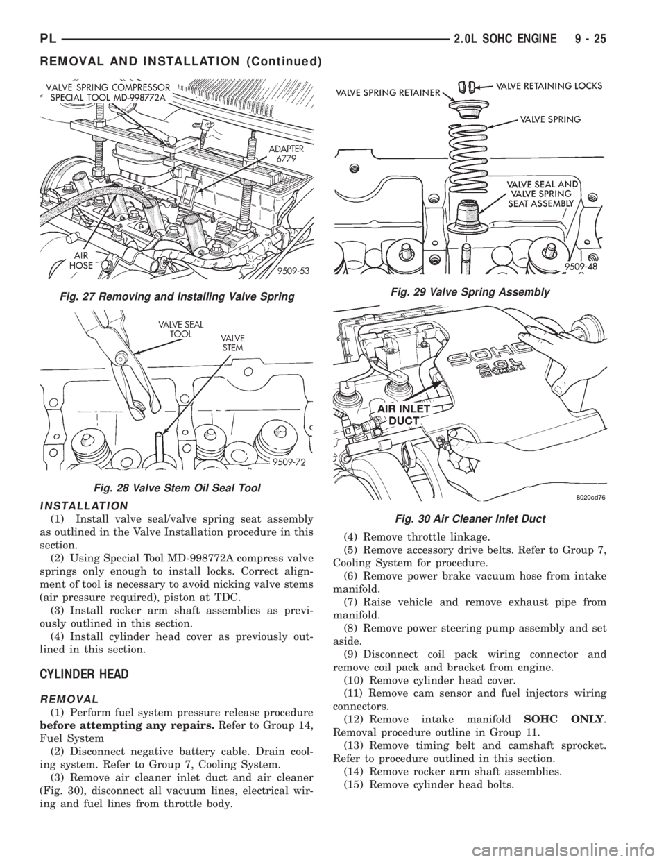
INSTALLATION
(1) Install valve seal/valve spring seat assembly
as outlined in the Valve Installation procedure in this
section.
(2) Using Special Tool MD-998772A compress valve
springs only enough to install locks. Correct align-
ment of tool is necessary to avoid nicking valve stems
(air pressure required), piston at TDC.
(3) Install rocker arm shaft assemblies as previ-
ously outlined in this section.
(4) Install cylinder head cover as previously out-
lined in this section.
CYLINDER HEAD
REMOVAL
(1) Perform fuel system pressure release procedure
before attempting any repairs.Refer to Group 14,
Fuel System
(2) Disconnect negative battery cable. Drain cool-
ing system. Refer to Group 7, Cooling System.
(3) Remove air cleaner inlet duct and air cleaner
(Fig. 30), disconnect all vacuum lines, electrical wir-
ing and fuel lines from throttle body.(4) Remove throttle linkage.
(5) Remove accessory drive belts. Refer to Group 7,
Cooling System for procedure.
(6) Remove power brake vacuum hose from intake
manifold.
(7) Raise vehicle and remove exhaust pipe from
manifold.
(8) Remove power steering pump assembly and set
aside.
(9) Disconnect coil pack wiring connector and
remove coil pack and bracket from engine.
(10) Remove cylinder head cover.
(11) Remove cam sensor and fuel injectors wiring
connectors.
(12) Remove intake manifoldSOHC ONLY.
Removal procedure outline in Group 11.
(13) Remove timing belt and camshaft sprocket.
Refer to procedure outlined in this section.
(14) Remove rocker arm shaft assemblies.
(15) Remove cylinder head bolts.
Fig. 27 Removing and Installing Valve Spring
Fig. 28 Valve Stem Oil Seal Tool
Fig. 29 Valve Spring Assembly
Fig. 30 Air Cleaner Inlet Duct
PL2.0L SOHC ENGINE 9 - 25
REMOVAL AND INSTALLATION (Continued)
Page 749 of 1200
the passenger compartment; at the lower edge of
instrument panel; near the steering column.
²Turn the ignition switch on and access the ªmis-
cellaneousº screen.
²Select ªre-learn cam/crankº option and follow
directions on DRB screen.
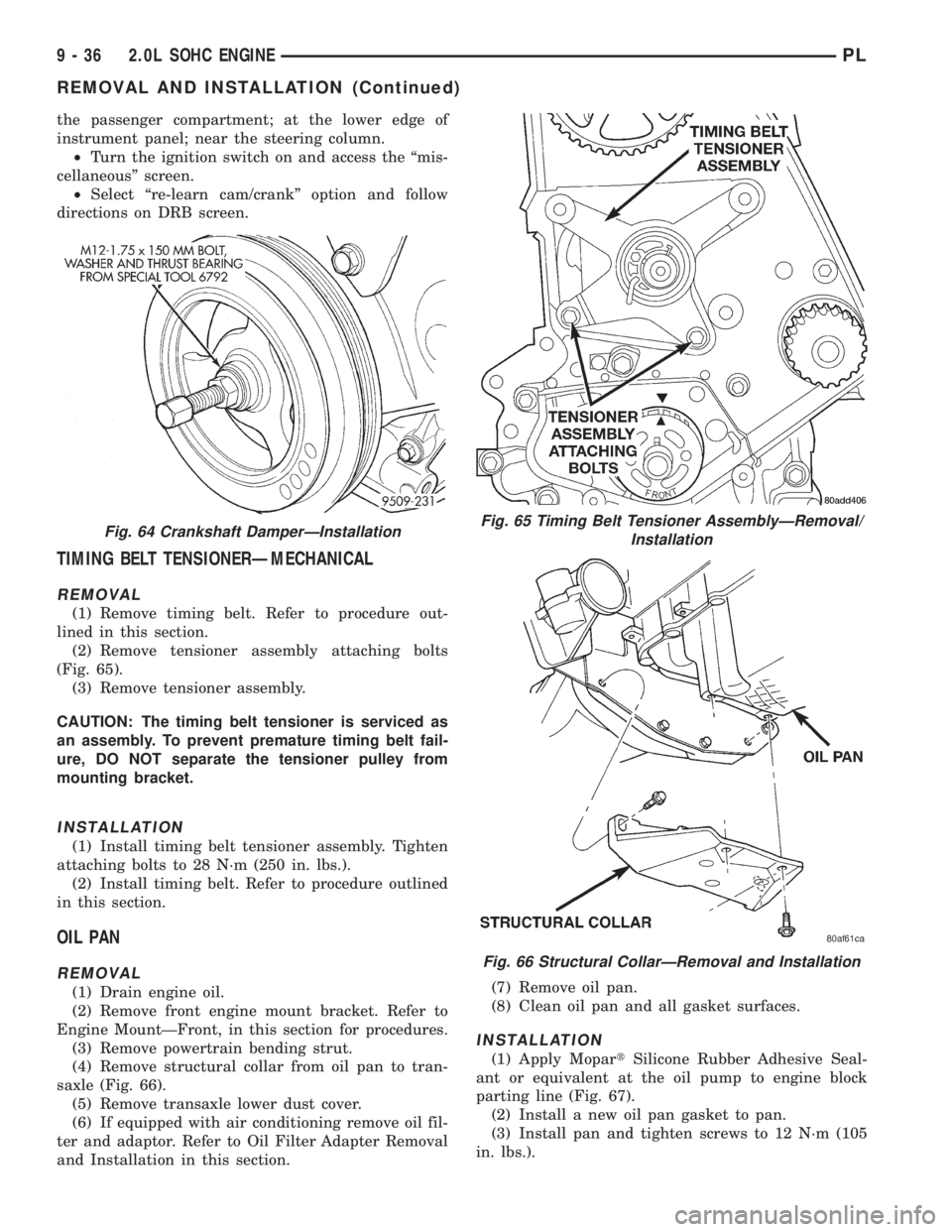
TIMING BELT TENSIONERÐMECHANICAL
REMOVAL
(1) Remove timing belt. Refer to procedure out-
lined in this section.
(2) Remove tensioner assembly attaching bolts
(Fig. 65).
(3) Remove tensioner assembly.
CAUTION: The timing belt tensioner is serviced as
an assembly. To prevent premature timing belt fail-
ure, DO NOT separate the tensioner pulley from
mounting bracket.
INSTALLATION
(1) Install timing belt tensioner assembly. Tighten
attaching bolts to 28 N´m (250 in. lbs.).
(2) Install timing belt. Refer to procedure outlined
in this section.
OIL PAN
REMOVAL
(1) Drain engine oil.
(2) Remove front engine mount bracket. Refer to
Engine MountÐFront, in this section for procedures.
(3) Remove powertrain bending strut.
(4) Remove structural collar from oil pan to tran-
saxle (Fig. 66).
(5) Remove transaxle lower dust cover.
(6) If equipped with air conditioning remove oil fil-
ter and adaptor. Refer to Oil Filter Adapter Removal
and Installation in this section.(7) Remove oil pan.
(8) Clean oil pan and all gasket surfaces.
INSTALLATION
(1) Apply MopartSilicone Rubber Adhesive Seal-
ant or equivalent at the oil pump to engine block
parting line (Fig. 67).
(2) Install a new oil pan gasket to pan.
(3) Install pan and tighten screws to 12 N´m (105
in. lbs.).
Fig. 64 Crankshaft DamperÐInstallationFig. 65 Timing Belt Tensioner AssemblyÐRemoval/
Installation
Fig. 66 Structural CollarÐRemoval and Installation
9 - 36 2.0L SOHC ENGINEPL
REMOVAL AND INSTALLATION (Continued)
Page 763 of 1200
CAUTION: When depressing the valve spring
retainers with valve spring compressor the locks
can become dislocated. Check to make sure both
locks are in their correct location after removing
tool.
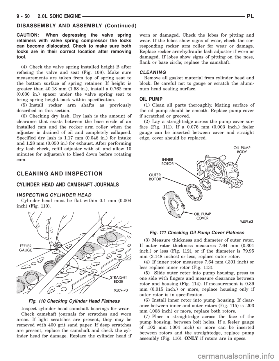
(4) Check the valve spring installed height B after
refacing the valve and seat (Fig. 108). Make sure
measurements are taken from top of spring seat to
the bottom surface of spring retainer. If height is
greater than 40.18 mm (1.58 in.), install a 0.762 mm
(0.030 in.) spacer under the valve spring seat to
bring spring height back within specification.
(5) Install rocker arm shafts as previously
described in this section.
(6) Checking dry lash. Dry lash is the amount of
clearance that exists between the base circle of an
installed cam and the rocker arm roller when the
adjuster is drained of oil and completely collapsed.
Specified dry lash is 1.17 mm (0.046 in.) for intake
and 1.28 mm (0.050 in.) for exhaust. After performing
dry lash check, refill adjuster with oil and allow 10
minutes for adjuster/s to bleed down before rotating
cam.
CLEANING AND INSPECTION
CYLINDER HEAD AND CAMSHAFT JOURNALS
INSPECTING CYLINDER HEAD
Cylinder head must be flat within 0.1 mm (0.004
inch) (Fig. 110).
Inspect cylinder head camshaft bearings for wear.
Check camshaft journals for scratches and worn
areas. If light scratches are present, they may be
removed with 400 grit sand paper. If deep scratches
are present, replace the camshaft and check the cyl-
inder head for damage. Replace the cylinder head ifworn or damaged. Check the lobes for pitting and
wear. If the lobes show signs of wear, check the cor-
responding rocker arm roller for wear or damage.
Replace rocker arm/hydraulic lash adjuster if worn or
damaged. If lobes show signs of pitting on the nose,
flank or base circle; replace the camshaft.
CLEANING
Remove all gasket material from cylinder head and
block. Be careful not to gouge or scratch the alumi-
num head sealing surface.
OIL PUMP
(1) Clean all parts thoroughly. Mating surface of
the oil pump should be smooth. Replace pump cover
if scratched or grooved.
(2) Lay a straightedge across the pump cover sur-
face (Fig. 111). If a 0.076 mm (0.003 inch.) feeler
gauge can be inserted between cover and straight
edge, cover should be replaced.
(3) Measure thickness and diameter of outer rotor.
If outer rotor thickness measures 7.64 mm (0.301
inch.) or less (Fig. 112), or if the diameter is 79.95
mm (3.148 inches) or less, replace outer rotor.
(4) If inner rotor measures 7.64 mm (.301 inch) or
less replace inner rotor (Fig. 113).
(5) Slide outer rotor into pump housing, press to
one side with fingers and measure clearance between
rotor and housing (Fig. 114). If measurement is 0.39
mm (0.015 inch.) or more, replace housing only if
outer rotor is in specification.
(6) Install inner rotor into pump housing. If clear-
ance between inner and outer rotors (Fig. 115) is .203
mm (.008 inch) or more, replace both rotors.
(7) Place a straightedge across the face of the
pump housing, between bolt holes. If a feeler gauge
of .102 mm (.004 inch) or more can be inserted
between rotors and the straightedge, replace pump
assembly (Fig. 116).ONLYif rotors are in specs.
Fig. 110 Checking Cylinder Head Flatness
Fig. 111 Checking Oil Pump Cover Flatness
9 - 50 2.0L SOHC ENGINEPL
DISASSEMBLY AND ASSEMBLY (Continued)
Page 767 of 1200
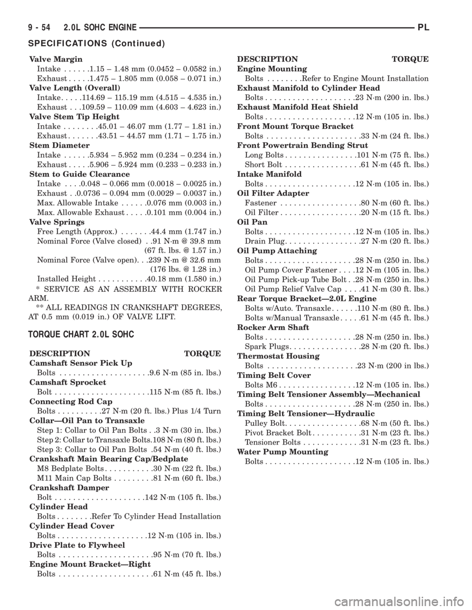
Valve Margin
Intake......1.15 ± 1.48 mm (0.0452 ± 0.0582 in.)
Exhaust.....1.475 ± 1.805 mm (0.058 ± 0.071 in.)
Valve Length (Overall)
Intake.....114.69 ± 115.19 mm (4.515 ± 4.535 in.)
Exhaust . . .109.59 ± 110.09 mm (4.603 ± 4.623 in.)
Valve Stem Tip Height
Intake........45.01 ± 46.07 mm (1.77 ± 1.81 in.)
Exhaust.......43.51 ± 44.57 mm (1.71 ± 1.75 in.)
Stem Diameter
Intake......5.934 ± 5.952 mm (0.234 ± 0.234 in.)
Exhaust.....5.906 ± 5.924 mm (0.233 ± 0.233 in.)
Stem to Guide Clearance
Intake. . . .0.048 ± 0.066 mm (0.0018 ± 0.0025 in.)
Exhaust . .0.0736 ± 0.094 mm (0.0029 ± 0.0037 in.)
Max. Allowable Intake......0.076 mm (0.003 in.)
Max. Allowable Exhaust.....0.101 mm (0.004 in.)
Valve Springs
Free Length (Approx.).......44.4 mm (1.747 in.)
Nominal Force (Valve closed) . .91 N´m @ 39.8 mm
(67 ft. lbs. @ 1.57 in.)
Nominal Force (Valve open). . .239 N´m @ 32.6 mm
(176 lbs. @ 1.28 in.)
Installed Height...........40.18 mm (1.580 in.)
* SERVICE AS AN ASSEMBLY WITH ROCKER
ARM.
** ALL READINGS IN CRANKSHAFT DEGREES,
AT 0.5 mm (0.019 in.) OF VALVE LIFT.
TORQUE CHART 2.0L SOHC
DESCRIPTION TORQUE
Camshaft Sensor Pick Up
Bolts....................9.6 N´m (85 in. lbs.)
Camshaft Sprocket
Bolt.....................115N´m(85ft.lbs.)
Connecting Rod Cap
Bolts..........27N´m(20ft.lbs.) Plus 1/4 Turn
CollarÐOil Pan to Transaxle
Step 1: Collar to Oil Pan Bolts . .3 N´m (30 in. lbs.)
Step 2: Collar to Transaxle Bolts.108 N´m (80 ft. lbs.)
Step 3: Collar to Oil Pan Bolts .54 N´m (40 ft. lbs.)
Crankshaft Main Bearing Cap/Bedplate
M8 Bedplate Bolts...........30N´m(22ft.lbs.)
M11 Main Cap Bolts.........81N´m(60ft.lbs.)
Crankshaft Damper
Bolt....................142 N´m (105 ft. lbs.)
Cylinder Head
Bolts........Refer To Cylinder Head Installation
Cylinder Head Cover
Bolts....................12N´m(105 in. lbs.)
Drive Plate to Flywheel
Bolts.....................95N´m(70ft.lbs.)
Engine Mount BracketÐRight
Bolts.....................61N´m(45ft.lbs.)DESCRIPTION TORQUE
Engine Mounting
Bolts........Refer to Engine Mount Installation
Exhaust Manifold to Cylinder Head
Bolts....................23N´m(200 in. lbs.)
Exhaust Manifold Heat Shield
Bolts....................12N´m(105 in. lbs.)
Front Mount Torque Bracket
Bolts.....................33N´m(24ft.lbs.)
Front Powertrain Bending Strut
Long Bolts................101 N´m (75 ft. lbs.)
Short Bolt.................61N´m(45ft.lbs.)
Intake Manifold
Bolts....................12N´m(105 in. lbs.)
Oil Filter Adapter
Fastener..................80N´m(60ft.lbs.)
Oil Filter..................20N´m(15ft.lbs.)
Oil Pan
Bolts....................12N´m(105 in. lbs.)
Drain Plug.................27N´m(20ft.lbs.)
Oil Pump Attaching
Bolts....................28N´m(250 in. lbs.)
Oil Pump Cover Fastener. . . .12 N´m (105 in. lbs.)
Oil Pump Pick-up Tube Bolt . .28 N´m (250 in. lbs.)
Oil Pump Relief Valve Cap. . . .41 N´m (30 ft. lbs.)
Rear Torque BracketÐ2.0L Engine
Bolts w/Auto. Transaxle......110N´m(80ft.lbs.)
Bolts w/Manual Transaxle.....61N´m(45ft.lbs.)
Rocker Arm Shaft
Bolts....................28N´m(250 in. lbs.)
Spark Plugs................28N´m(20ft.lbs.)
Thermostat Housing
Bolts....................23N´m(200 in lbs.)
Timing Belt Cover
Bolts M6.................12N´m(105 in. lbs.)
Timing Belt Tensioner AssemblyÐMechanical
Bolts....................28N´m(250 in. lbs.)
Timing Belt TensionerÐHydraulic
Pulley Bolt.................68N´m(50ft.lbs.)
Pivot Bracket Bolt...........31N´m(23ft.lbs.)
Tensioner Bolts.............31N´m(23ft.lbs.)
Water Pump Mounting
Bolts....................12N´m(105 in. lbs.)
9 - 54 2.0L SOHC ENGINEPL
SPECIFICATIONS (Continued)
Page 778 of 1200
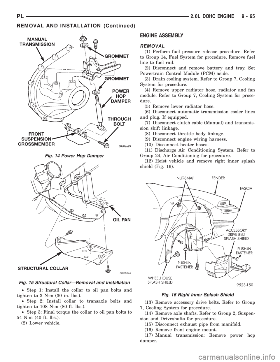
²Step 1: Install the collar to oil pan bolts and
tighten to 3 N´m (30 in. lbs.).
²Step 2: Install collar to transaxle bolts and
tighten to 108 N´m (80 ft. lbs.).
²Step 3: Final torque the collar to oil pan bolts to
54 N´m (40 ft. lbs.).
(2) Lower vehicle.
ENGINE ASSEMBLY
REMOVAL
(1) Perform fuel pressure release procedure. Refer
to Group 14, Fuel System for procedure. Remove fuel
line to fuel rail.
(2) Disconnect and remove battery and tray. Set
Powertrain Control Module (PCM) aside.
(3) Drain cooling system. Refer to Group 7, Cooling
System for procedure.
(4) Remove upper radiator hose, radiator and fan
module. Refer to Group 7, Cooling System for proce-
dure.
(5) Remove lower radiator hose.
(6) Disconnect automatic transmission cooler lines
and plug. If equipped.
(7) Disconnect clutch cable (Manual) and transmis-
sion shift linkage.
(8) Disconnect throttle body linkage.
(9) Disconnect engine wiring harness.
(10) Disconnect heater hoses.
(11) Discharge Air Conditioning System. Refer to
Group 24, Air Conditioning for procedure.
(12) Hoist vehicle and remove right inner splash
shield (Fig. 16).
(13) Remove accessory drive belts. Refer to Group
7, Cooling System for procedure.
(14) Remove axle shafts. Refer to Group 2, Suspen-
sion and Driveshafts for procedure.
(15) Disconnect exhaust pipe from manifold.
(16) Remove front engine mount.
(17) Manual transmission: Remove power hop
damper.
Fig. 14 Power Hop Damper
Fig. 15 Structural CollarÐRemoval and Installation
Fig. 16 Right Inner Splash Shield
PL2.0L DOHC ENGINE 9 - 65
REMOVAL AND INSTALLATION (Continued)
Page 785 of 1200
REMOVAL
(1) Perform fuel system pressure release procedure
before attempting any repairs.Refer to Group 14,
Fuel System.
(2) Disconnect negative battery cable. Drain cool-
ing system. Refer to Group 7, Cooling System.
(3) Remove air cleaner duct and air cleaner, dis-
connect all vacuum lines, electrical wiring and fuel
line from fuel rail and throttle body.
(4) Remove throttle linkage.
(5) Remove accessory drive belts. Refer to Group 7,
Cooling System for procedure.
(6) Remove power brake vacuum hose from intake
manifold.
(7) Raise vehicle and remove exhaust pipe from
manifold.
(8) Remove power steering pump assembly and set
aside.
(9) Disconnect coil pack wiring connector and
remove coil pack from engine.
(10) Remove cam sensor and fuel injectors wiring
connectors.
(11) Remove timing belt, timing belt tensioner, and
camshaft sprocket. Refer to procedure outlined in
this section.
(12) Remove inner timing belt cover.
(13) Remove cylinder head cover.
(14) Remove camshaft and cam follower assem-
blies. Refer to Camshaft Service for removal proce-
dure outlined in this section.
(15) Remove cylinder head bolts.
CAUTION: Use only a plastic scraper to remove
gasket material on the aluminum head sealing sur-
faces to prevent damage to cylinder head.
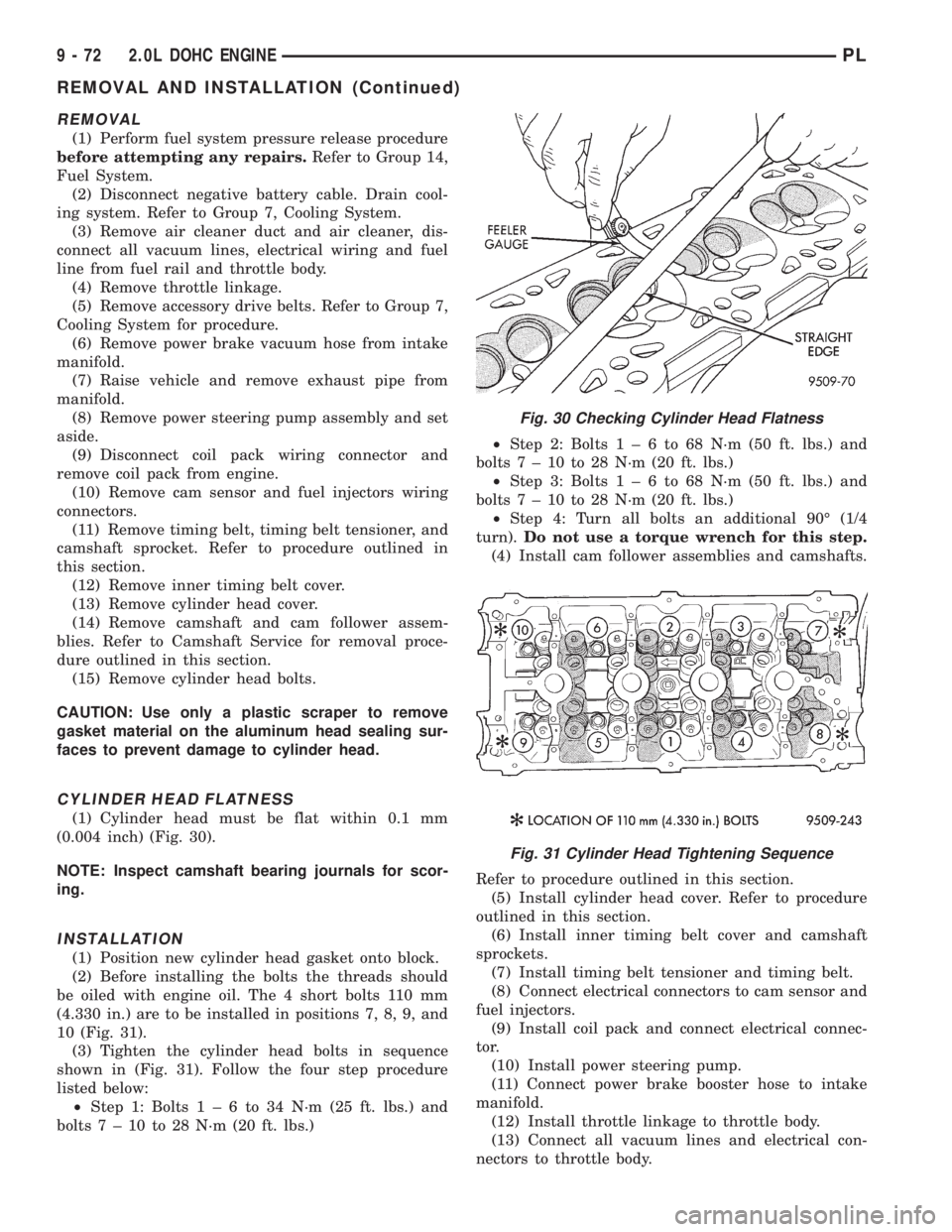
CYLINDER HEAD FLATNESS
(1) Cylinder head must be flat within 0.1 mm
(0.004 inch) (Fig. 30).
NOTE: Inspect camshaft bearing journals for scor-
ing.
INSTALLATION
(1) Position new cylinder head gasket onto block.
(2) Before installing the bolts the threads should
be oiled with engine oil. The 4 short bolts 110 mm
(4.330 in.) are to be installed in positions 7, 8, 9, and
10 (Fig. 31).
(3) Tighten the cylinder head bolts in sequence
shown in (Fig. 31). Follow the four step procedure
listed below:
²Step 1: Bolts1±6to34N´m(25ft.lbs.) and
bolts7±10to28N´m(20ft.lbs.)²Step 2: Bolts1±6to68N´m(50ft.lbs.) and
bolts7±10to28N´m(20ft.lbs.)
²Step 3: Bolts1±6to68N´m(50ft.lbs.) and
bolts7±10to28N´m(20ft.lbs.)
²Step 4: Turn all bolts an additional 90É (1/4
turn).Do not use a torque wrench for this step.
(4) Install cam follower assemblies and camshafts.
Refer to procedure outlined in this section.
(5) Install cylinder head cover. Refer to procedure
outlined in this section.
(6) Install inner timing belt cover and camshaft
sprockets.
(7) Install timing belt tensioner and timing belt.
(8) Connect electrical connectors to cam sensor and
fuel injectors.
(9) Install coil pack and connect electrical connec-
tor.
(10) Install power steering pump.
(11) Connect power brake booster hose to intake
manifold.
(12) Install throttle linkage to throttle body.
(13) Connect all vacuum lines and electrical con-
nectors to throttle body.
Fig. 30 Checking Cylinder Head Flatness
Fig. 31 Cylinder Head Tightening Sequence
9 - 72 2.0L DOHC ENGINEPL
REMOVAL AND INSTALLATION (Continued)