power steering fluid DODGE NEON 1999 Service Repair Manual
[x] Cancel search | Manufacturer: DODGE, Model Year: 1999, Model line: NEON, Model: DODGE NEON 1999Pages: 1200, PDF Size: 35.29 MB
Page 3 of 1200
ENGINE OIL
SAE VISCOSITY RATING INDICATES ENGINE OIL VISCOSITY
An SAE viscosity grade is used to specify the vis-
cosity of engine oil. SAE 30 specifies a single viscos-
ity engine oil. Engine oils also have multiple
viscosities. These are specified with a dual SAE vis-
cosity grade which indicates the cold-to-hot tempera-
ture viscosity range.
²SAE 30 = single grade engine oil.
²SAE 10W-30 = multiple grade engine oil.
API QUALITY CLASSIFICATION
The API Service Grade specifies the type of perfor-
mance the engine oil is intended to provide. The API
Service Grade specifications also apply to energy con-
serving engine oils.
Use engine oils that are API Service Certified.
5W-30 and 10W-30 MOPAR engine oils conform to
specifications.
Refer to Group 9, Engine for engine oil specifica-
tion.
GEAR LUBRICANTS
SAE ratings also apply to multiple grade gear
lubricants. In addition, API classification defines the
lubricants usage.
LUBRICANTS AND GREASES
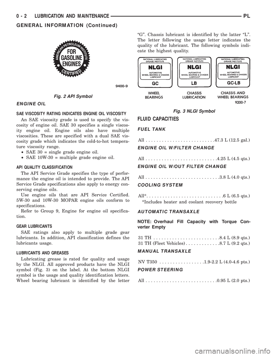
Lubricating grease is rated for quality and usage
by the NLGI. All approved products have the NLGI
symbol (Fig. 3) on the label. At the bottom NLGI
symbol is the usage and quality identification letters.
Wheel bearing lubricant is identified by the letterªGº. Chassis lubricant is identified by the latter ªLº.
The letter following the usage letter indicates the
quality of the lubricant. The following symbols indi-
cate the highest quality.
FLUID CAPACITIES
FUEL TANK
All ..........................47.3 L (12.5 gal.)
ENGINE OIL W/FILTER CHANGE
All...........................4.25 L (4.5 qts.)
ENGINE OIL W/OUT FILTER CHANGE
All............................3.8 L (4.0 qts.)
COOLING SYSTEM
All*.............................6L(6.5 qts.)
*Includes heater and coolant recovery bottle
AUTOMATIC TRANSAXLE
NOTE: Overhaul Fill Capacity with Torque Con-
verter Empty
31TH .........................8.4 L (8.9 qts.)
31 TH (Fleet Vehicles).............8.7 L (9.2 qts.)
MANUAL TRANSAXLE
NV T350.................1.9-2.2 L (4.0-4.6 pts.)
POWER STEERING
All...........................0.95 L (2.0 pts.)
Fig. 2 API Symbol
Fig. 3 NLGI Symbol
0 - 2 LUBRICATION AND MAINTENANCEPL
GENERAL INFORMATION (Continued)
Page 4 of 1200
MAINTENANCE SCHEDULES
INDEX
page page
GENERAL INFORMATION
INTRODUCTION......................... 3
SCHEDULE ± A.......................... 3SCHEDULE ± B.......................... 4
UNSCHEDULED INSPECTION............... 3
GENERAL INFORMATION
INTRODUCTION
Service and maintenance procedures for compo-
nents and systems listed in Schedule ± A or B can be
found by using the Group Tab Locator index at the
front of this manual. If it is not clear which group
contains the information needed, refer to the index at
the back of this manual.
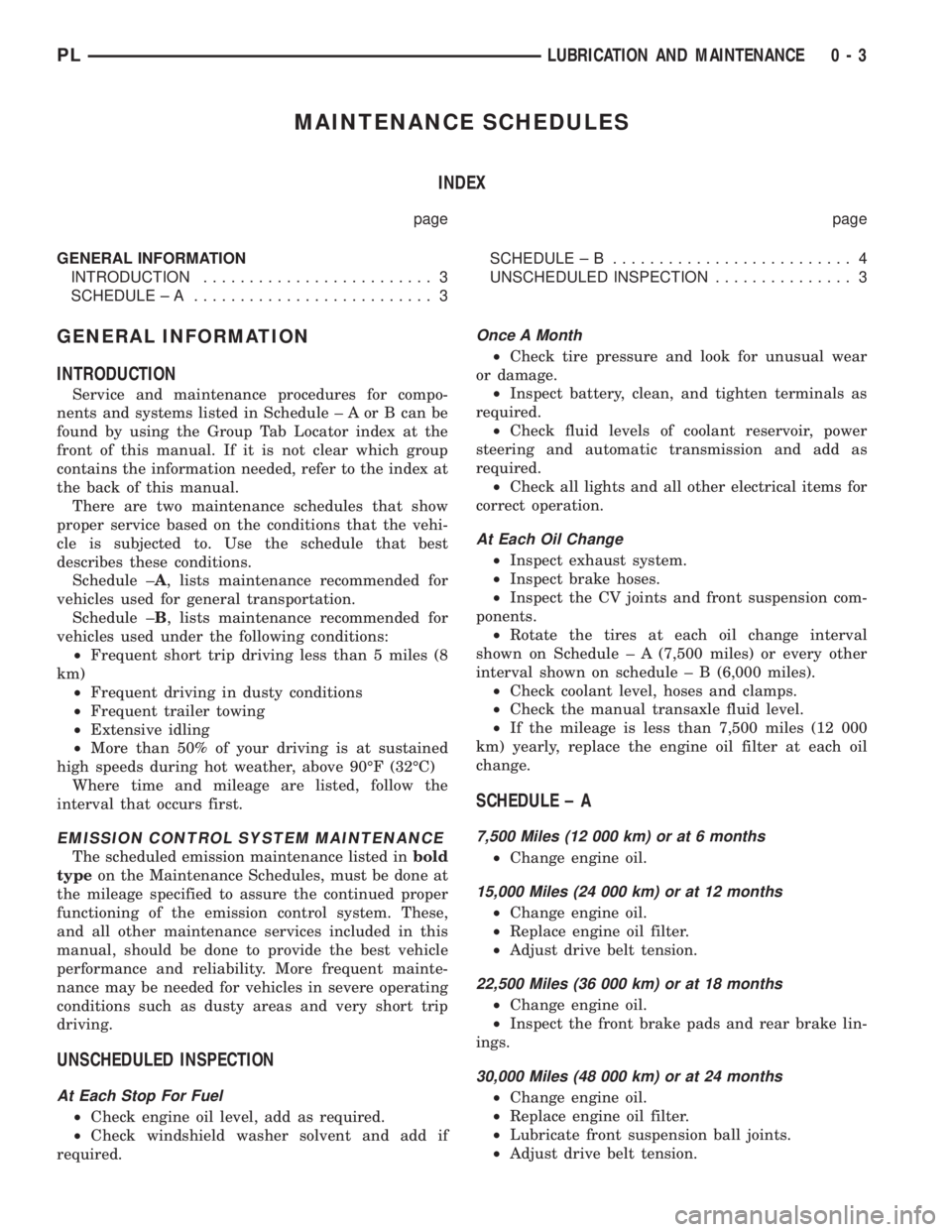
There are two maintenance schedules that show
proper service based on the conditions that the vehi-
cle is subjected to. Use the schedule that best
describes these conditions.
Schedule ±A, lists maintenance recommended for
vehicles used for general transportation.
Schedule ±B, lists maintenance recommended for
vehicles used under the following conditions:
²Frequent short trip driving less than 5 miles (8
km)
²Frequent driving in dusty conditions
²Frequent trailer towing
²Extensive idling
²More than 50% of your driving is at sustained
high speeds during hot weather, above 90ÉF (32ÉC)
Where time and mileage are listed, follow the
interval that occurs first.
EMISSION CONTROL SYSTEM MAINTENANCE
The scheduled emission maintenance listed inbold
typeon the Maintenance Schedules, must be done at
the mileage specified to assure the continued proper
functioning of the emission control system. These,
and all other maintenance services included in this
manual, should be done to provide the best vehicle
performance and reliability. More frequent mainte-
nance may be needed for vehicles in severe operating
conditions such as dusty areas and very short trip
driving.
UNSCHEDULED INSPECTION
At Each Stop For Fuel
²Check engine oil level, add as required.
²Check windshield washer solvent and add if
required.
Once A Month
²Check tire pressure and look for unusual wear
or damage.
²Inspect battery, clean, and tighten terminals as
required.
²Check fluid levels of coolant reservoir, power
steering and automatic transmission and add as
required.
²Check all lights and all other electrical items for
correct operation.
At Each Oil Change
²Inspect exhaust system.
²Inspect brake hoses.
²Inspect the CV joints and front suspension com-
ponents.
²Rotate the tires at each oil change interval
shown on Schedule ± A (7,500 miles) or every other
interval shown on schedule ± B (6,000 miles).
²Check coolant level, hoses and clamps.
²Check the manual transaxle fluid level.
²If the mileage is less than 7,500 miles (12 000
km) yearly, replace the engine oil filter at each oil
change.
SCHEDULE ± A
7,500 Miles (12 000 km) or at 6 months
²Change engine oil.
15,000 Miles (24 000 km) or at 12 months
²Change engine oil.
²Replace engine oil filter.
²Adjust drive belt tension.
22,500 Miles (36 000 km) or at 18 months
²Change engine oil.
²Inspect the front brake pads and rear brake lin-
ings.
30,000 Miles (48 000 km) or at 24 months
²Change engine oil.
²Replace engine oil filter.
²Lubricate front suspension ball joints.
²Adjust drive belt tension.
PLLUBRICATION AND MAINTENANCE 0 - 3
Page 15 of 1200
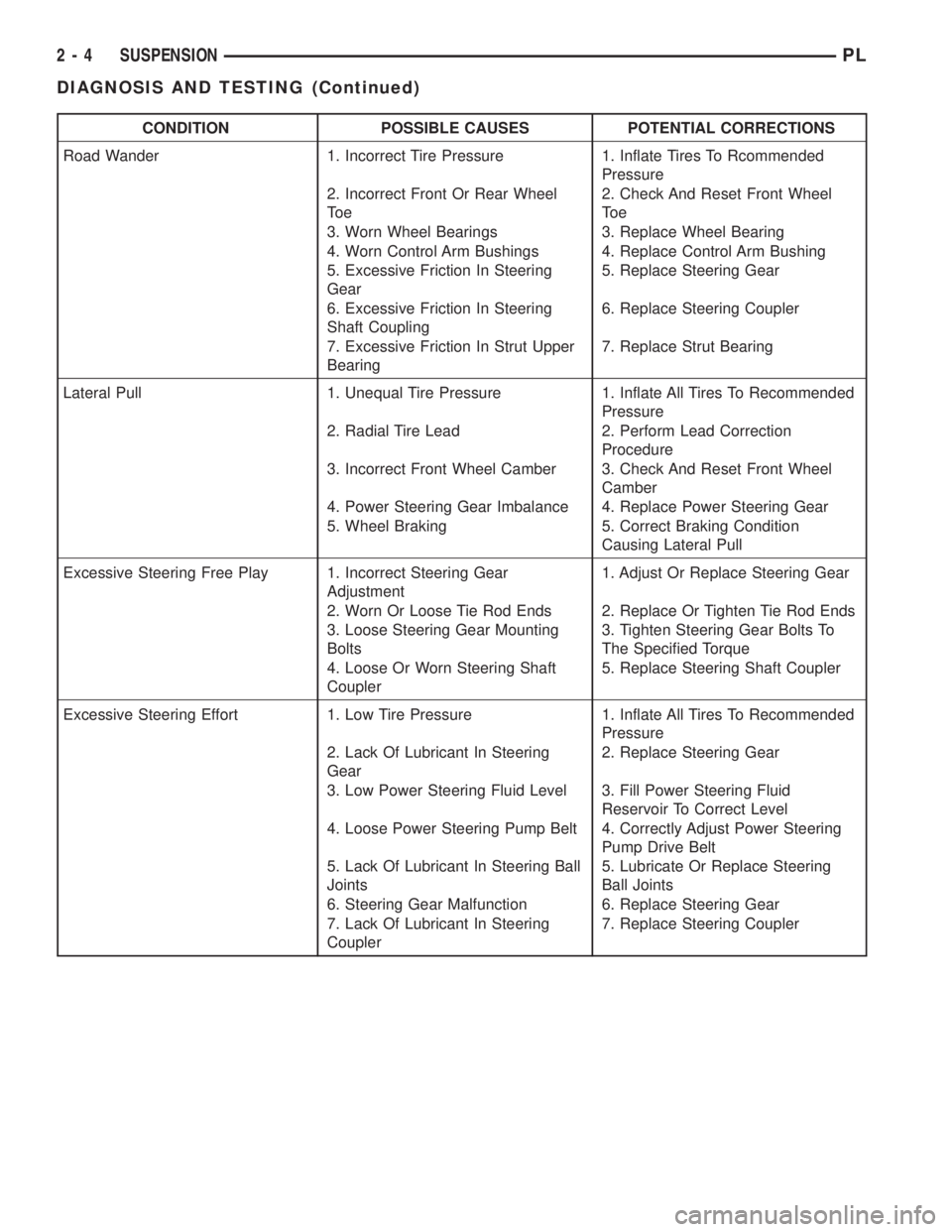
CONDITION POSSIBLE CAUSES POTENTIAL CORRECTIONS
Road Wander 1. Incorrect Tire Pressure 1. Inflate Tires To Rcommended
Pressure
2. Incorrect Front Or Rear Wheel
To e2. Check And Reset Front Wheel
To e
3. Worn Wheel Bearings 3. Replace Wheel Bearing
4. Worn Control Arm Bushings 4. Replace Control Arm Bushing
5. Excessive Friction In Steering
Gear5. Replace Steering Gear
6. Excessive Friction In Steering
Shaft Coupling6. Replace Steering Coupler
7. Excessive Friction In Strut Upper
Bearing7. Replace Strut Bearing
Lateral Pull 1. Unequal Tire Pressure 1. Inflate All Tires To Recommended
Pressure
2. Radial Tire Lead 2. Perform Lead Correction
Procedure
3. Incorrect Front Wheel Camber 3. Check And Reset Front Wheel
Camber
4. Power Steering Gear Imbalance 4. Replace Power Steering Gear
5. Wheel Braking 5. Correct Braking Condition
Causing Lateral Pull
Excessive Steering Free Play 1. Incorrect Steering Gear
Adjustment1. Adjust Or Replace Steering Gear
2. Worn Or Loose Tie Rod Ends 2. Replace Or Tighten Tie Rod Ends
3. Loose Steering Gear Mounting
Bolts3. Tighten Steering Gear Bolts To
The Specified Torque
4. Loose Or Worn Steering Shaft
Coupler5. Replace Steering Shaft Coupler
Excessive Steering Effort 1. Low Tire Pressure 1. Inflate All Tires To Recommended
Pressure
2. Lack Of Lubricant In Steering
Gear2. Replace Steering Gear
3. Low Power Steering Fluid Level 3. Fill Power Steering Fluid
Reservoir To Correct Level
4. Loose Power Steering Pump Belt 4. Correctly Adjust Power Steering
Pump Drive Belt
5. Lack Of Lubricant In Steering Ball
Joints5. Lubricate Or Replace Steering
Ball Joints
6. Steering Gear Malfunction 6. Replace Steering Gear
7. Lack Of Lubricant In Steering
Coupler7. Replace Steering Coupler
2 - 4 SUSPENSIONPL
DIAGNOSIS AND TESTING (Continued)
Page 148 of 1200
(3) Remove the rubber plug from the adjusting
hole in the brake shoe backing plate on both sides of
the vehicle.
(4)Driver (left) side park brake shoe adjust-
ment procedure.Insert a medium size screwdriver
through adjustment hole in backing plate. Position
the srewdriver against the starwheel on the park
brake shoe adjuster mechanism. Using the screw-
driver rotate the starwheeldownwarduntil a slight
drag is felt when turning the rear tire and wheel.
Then, using the screwdriver rotate the starwheel
upwardjust until the rear tire and wheel can be
rotated with no park brake shoe drag. From the
point where there is no more park brake drag rotate
the starwheelupwarda maximum of two additional
clicks. The park brake shoe to drum clearance is
know properly adjusted.
(5)Passenger (right) side park brake shoe
adjustment procedure.Insert a medium size
screwdriver through adjustment hole in backing
plate. Position the srewdriver against the starwheel
on the park brake shoe adjuster mechanism. Using
the screwdriver rotate the starwheelupwarduntil a
slight drag is felt when turning the rear tire and
wheel. Then, using the screwdriver rotate the star-
wheeldownwardjust until the rear tire and wheel
can be rotated with no park brake shoe drag. From
the point where there is no more park brake drag
rotate the starwheeldownwarda maximum of two
additional clicks. The park brake shoe to drum clear-
ance is know properly adjusted.
(6) Install the rubber plug in the adjusting hole on
the brake shoe backing plate on both sides of the
vehicle.
(7) Lower vehicle far enough to allow access the
park brake lever. The rear tires must not be on the
ground.
(8) Fully apply and release the park brakes two
times after adjusting the park brake shoes. Then
rotate both rear wheels to ensure that the park
brake shoes do not drag on the brake drum following
the application and release of the park brakes.
SPECIFICATIONS
BRAKE FLUID
The brake fluid used in this vehicle must conform
to DOT 3 specifications and SAE J1703 standards.
No other type of brake fluid is recommended or
approved for usage in the vehicle brake system. Use
only Mopar brake fluid or an equivalent from a
tightly sealed container.
CAUTION: Never use reclaimed brake fluid or fluid
from an container which has been left open. Anopen container will absorb moisture from the air
and contaminate the fluid.
CAUTION: Never use any type of a petroleum-
based fluid in the brake hydraulic system. Use of
such type fluids will result in seal damage of the
vehicle brake hydraulic system causing a failure of
the vehicle brake system. Petroleum based fluids
would be items such as engine oil, transmission
fluid, power steering fluid ect.
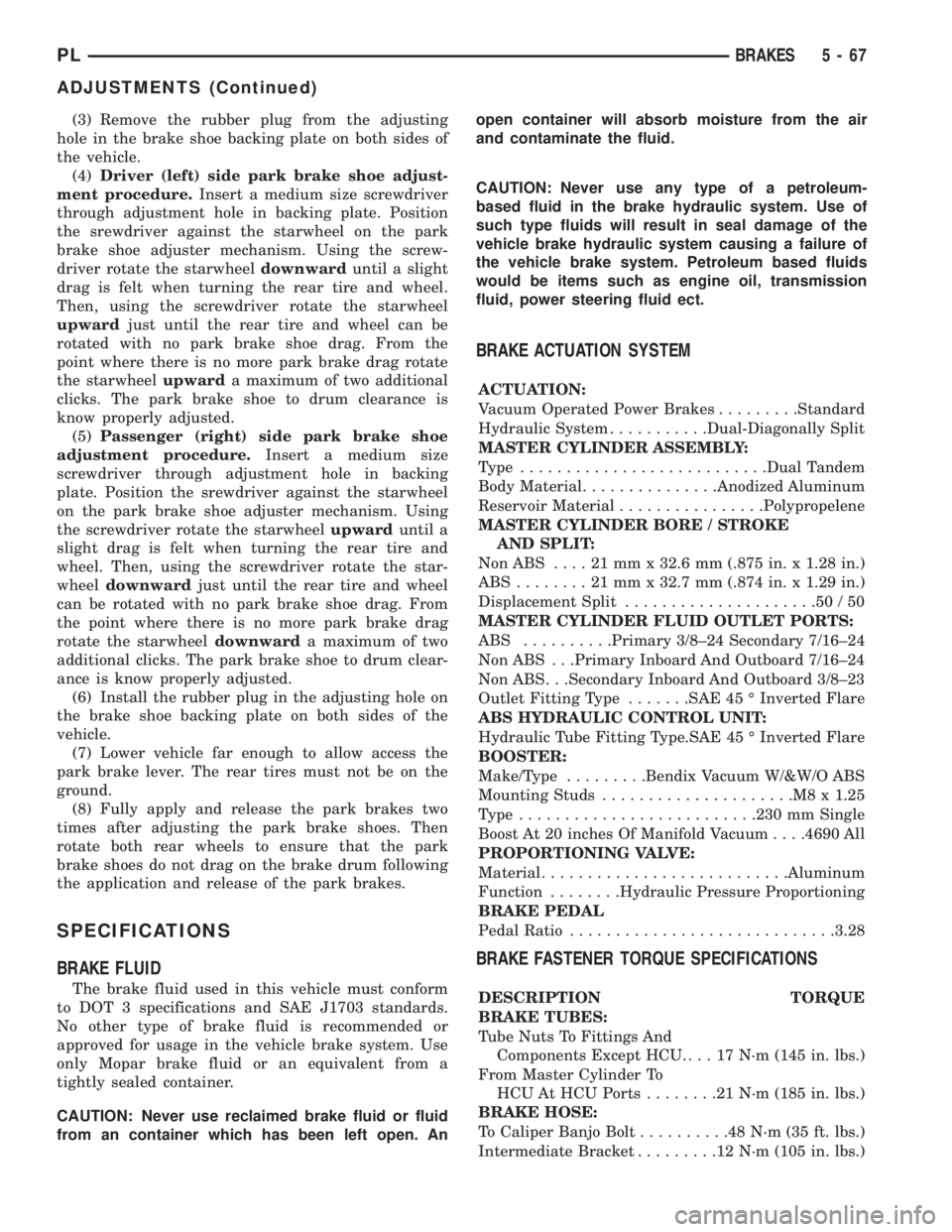
BRAKE ACTUATION SYSTEM
ACTUATION:
Vacuum Operated Power Brakes.........Standard
Hydraulic System...........Dual-Diagonally Split
MASTER CYLINDER ASSEMBLY:
Type ...........................Dual Tandem
Body Material...............Anodized Aluminum
Reservoir Material................Polypropelene
MASTER CYLINDER BORE / STROKE
AND SPLIT:
NonABS ....21mmx32.6 mm (.875 in. x 1.28 in.)
ABS........21mmx32.7 mm (.874 in. x 1.29 in.)
Displacement Split.....................50/50
MASTER CYLINDER FLUID OUTLET PORTS:
ABS ..........Primary 3/8±24 Secondary 7/16±24
Non ABS . . .Primary Inboard And Outboard 7/16±24
Non ABS . . .Secondary Inboard And Outboard 3/8±23
Outlet Fitting Type.......SAE 45 É Inverted Flare
ABS HYDRAULIC CONTROL UNIT:
Hydraulic Tube Fitting Type.SAE 45 É Inverted Flare
BOOSTER:
Make/Type.........Bendix Vacuum W/&W/O ABS
Mounting Studs.....................M8x1.25
Type ..........................230 mm Single
Boost At 20 inches Of Manifold Vacuum. . . .4690 All
PROPORTIONING VALVE:
Material...........................Aluminum
Function........Hydraulic Pressure Proportioning
BRAKE PEDAL
Pedal Ratio.............................3.28
BRAKE FASTENER TORQUE SPECIFICATIONS
DESCRIPTION TORQUE
BRAKE TUBES:
Tube Nuts To Fittings And
Components Except HCU. . . . 17 N´m (145 in. lbs.)
From Master Cylinder To
HCU At HCU Ports........21N´m(185 in. lbs.)
BRAKE HOSE:
To Caliper Banjo Bolt..........48N´m(35ft.lbs.)
Intermediate Bracket.........12N´m(105 in. lbs.)
PLBRAKES 5 - 67
ADJUSTMENTS (Continued)
Page 150 of 1200
ANTILOCK BRAKE SYSTEM±TEVES MARK 20
INDEX
page page
DESCRIPTION AND OPERATION
ABS BRAKE SYSTEM COMPONENTS........ 71
ABS BRAKES OPERATION AND VEHICLE
PERFORMANCE....................... 69
ABS COMPONENT ABBREVIATION LIST...... 69
ABS FLUID ACCUMULATORS.............. 72
ABS FUSES............................ 73
ABS MASTER CYLINDER AND POWER BRAKE
BOOSTER............................ 71
ABS RELAYS........................... 73
ABS WARNING LAMP (YELLOW)............ 75
ANTILOCK BRAKES OPERATION
DESCRIPTION........................ 69
CONTROLLER ANTILOCK BRAKES (CAB)..... 74
HCU PUMP/MOTOR..................... 72
HYDRAULIC CIRCUITS AND VALVE
OPERATION.......................... 75
INLET VALVES AND SOLENOIDS............ 72
INTEGRATED CONTROL UNIT (ICU)......... 71
OUTLET VALVES AND SOLENOIDS.......... 72
PROPORTIONING VALVE................. 73
WHEEL SPEED SENSORS................. 73
DIAGNOSIS AND TESTING
ABS DIAGNOSTIC TROUBLE CODES........ 78
ABS DIAGNOSTICS MANUAL.............. 76
ABS GENERAL DIAGNOSTICS INFORMATION . 75
ABS SERVICE PRECAUTIONS.............. 76
ABS SYSTEM SELF DIAGNOSTICS.......... 77ABS WIRING DIAGRAM INFORMATION....... 76
BRAKE FLUID CONTAMINATION............ 80
DRB DIAGNOSTIC CONNECTOR............ 77
DRB DIAGNOSTIC SCAN TOOL USAGE...... 77
INTERMITTENT DIAGNOSTIC TROUBLE
CODES.............................. 78
PROPORTIONING VALVE................. 79
TEST DRIVING ABS COMPLAINT VEHICLE.... 80
TONEWHEEL INSPECTION................ 79
SERVICE PROCEDURES
BLEEDING TEVES MARK 20 HYDRAULIC
SYSTEM............................. 81
BRAKE FLUID LEVEL INSPECTION.......... 80
REMOVAL AND INSTALLATION
ABS GENERAL SERVICE PRECAUTIONS..... 81
ABS HYDRAULIC CONTROL UNIT........... 82
CONTROLLER ANTILOCK BRAKES (CAB)..... 86
FRONT WHEEL SPEED SENSOR........... 87
MASTER CYLINDER AND POWER BRAKE
BOOSTER............................ 86
PROPORTIONING VALVES................ 86
REAR WHEEL SPEED SENSOR............ 88
SPECIFICATIONS
BRAKE FASTENER TORQUE SPECIFICATIONS . 89
SPEED SENSOR TONE WHEEL RUNOUT..... 89
WHEEL SPEED SENSOR TO TONE WHEEL
CLEARANCE.......................... 89
DESCRIPTION AND OPERATION
ANTILOCK BRAKES OPERATION DESCRIPTION
The purpose of an Antilock Brake System (ABS) is
to prevent wheel lock-up under braking conditions on
virtually any type of road surface. Antilock Braking
is desirable because a vehicle which is stopped with-
out locking the wheels will retain directional stability
and some steering capability. This allows the driver
to retain greater control of the vehicle during brak-
ing.
This section of the service manual covers the
description and on car service for the ITT Teves
Mark 20 ABS Brake System. If other service is
required on the non ABS related components of the
brake system, refer to the appropriate section in this
group of the service manual for the specific service
procedure required.
ABS COMPONENT ABBREVIATION LIST
In this section of the service manual, several
abbreviations are used for the components of the
Teves Mark 20 ABS Brake System. They are listed
below for your reference.
²CAB±Controller Antilock Brake
²ICU±Integrated Control Unit
²HCU±Hydraulic Control Unit
²ABS±Antilock Brake System
²PSI±Pounds Per Square Inch (pressure)
²WSS±Wheel Speed Sensor
²FWD±Front Wheel Drive
²DTC±Diagnostic Trouble Code
ABS BRAKES OPERATION AND VEHICLE
PERFORMANCE
This ABS System represents the current state-of-
the-art in vehicle braking systems and offers the
driver increased safety and control during braking.
PLBRAKES 5 - 69
Page 152 of 1200
PREMATURE ABS CYCLING
NOTE: When working on a vehicle which has a
complaint of premature ABS cycling it may be nec-
essary to use a DRB Scan Tool to detect and verify
the condition.
There is one complaint called Premature ABS
Cycling in which neither the Red Brake Warning
Lamp nor the Amber Antilock Lamp were illumi-
nated and no fault codes were stored in the CAB.
Symptoms of Premature ABS Cycling, include click-
ing sounds from the solenoids valves, pump motor
running and pulsations in the brake pedal. This con-
dition can occur at any braking rate of the vehicle
and on any type of road surface. This creates an
additional condition which needs to be correctly
assessed when diagnosing problems with the antilock
brake system.
The following conditions are common causes that
need to be checked when diagnosing a condition of
Premature ABS Cycling. Damaged tone wheels,
incorrect tone wheels, damage to a wheel speed sen-
sor mounting boss on a steering knuckle, a loose
wheel speed sensor mounting bolt, and excessive tone
wheel runout. Also, an excessively large tone wheel
to wheel speed sensor air gap can lead to the condi-
tion of Premature ABS Cycling. Special attention is
to be given to these components when diagnosing a
vehicle exhibiting the condition of Premature ABS
Cycling. After diagnosing the defective component,
repair or replace as required.
When the component repair or replacement is com-
pleted, test drive the vehicle to verify the condition of
Premature ABS Cycling has been corrected.
ABS BRAKE SYSTEM COMPONENTS
The following is a detailed description of the Teves
Mark 20 ABS brake system components. For infor-
mation on servicing the base brake system compo-
nents, see the base Brake System section of this
Service Manual.
ABS MASTER CYLINDER AND POWER BRAKE
BOOSTER
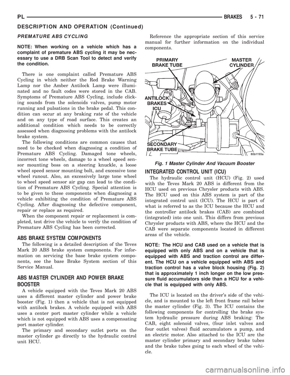
A vehicle equipped with the Teves Mark 20 ABS
uses a different master cylinder and power brake
booster (Fig. 1) then a vehicle that is not equipped
with antilock brakes. A vehicle equipped with ABS
uses a center port master cylinder while a vehicle
which is not equipped with ABS uses a compensating
port master cylinder.
The primary and secondary outlet ports on the
master cylinder go directly to the hydraulic control
unit HCU.Reference the appropriate section of this service
manual for further information on the individual
components.
INTEGRATED CONTROL UNIT (ICU)
The hydraulic control unit (HCU) (Fig. 2) used
with the Teves Mark 20 ABS is different from the
HCU used on previous Chrysler products with ABS.
The HCU used on this ABS system is part of the
integrated control unit (ICU). The HCU is part of
what is referred to as the ICU because the HCU and
the controller antilock brakes (CAB) are combined
(integrated) into one unit. This differs from previous
Chrysler products with ABS, where the HCU and the
CAB were separate components located in different
areas of the vehicle.
NOTE: The HCU and CAB used on a vehicle that is
equipped with only ABS and on a vehicle that is
equipped with ABS and traction control are differ-
ent. The HCU on a vehicle equipped with ABS and
traction control has a valve block housing (Fig. 2)
that is approximately 1 inch longer on the low pres-
sure fluid accumulators side than a HCU for a vehi-
cle that is equipped with only ABS.
The ICU is located on the driver's side of the vehi-
cle, and is mounted to the left front frame rail below
the master cylinder (Fig. 3). The ICU contains the
following components for controlling the brake sys-
tem hydraulic pressure during ABS braking: The
CAB, eight solenoid valves, (four inlet valves and
four outlet valves) fluid accumulators a pump, and
an electric motor. Also attached to the ICU are the
master cylinder primary and secondary brake tubes
and the brake tubes going to each wheel of the vehi-
cle.
Fig. 1 Master Cylinder And Vacuum Booster
PLBRAKES 5 - 71
DESCRIPTION AND OPERATION (Continued)
Page 858 of 1200
(2) Disconnect vapor tube from rollover valve.
(3) Using a straight screwdriver, pry the valve out
of the grommet in the fuel filler tube.
INSTALLATION
(1) Apply a light coating of power steering fluid to
the grommet.
(2) Install valve in grommet.
(3) Attach vapor tube to valve.
(4) Install fuel filler tube cap.
ACCELERATOR PEDAL
CAUTION: When servicing the accelerator pedal,
throttle cable or speed control cable, do not dam-
age or kink the core wire inside the cable sheath-
ing.
REMOVAL
(1) Working from the engine compartment, remove
the throttle control shield.
(2) Hold the throttle body throttle lever in the
wide open position. Remove the throttle cable from
the throttle body cam.
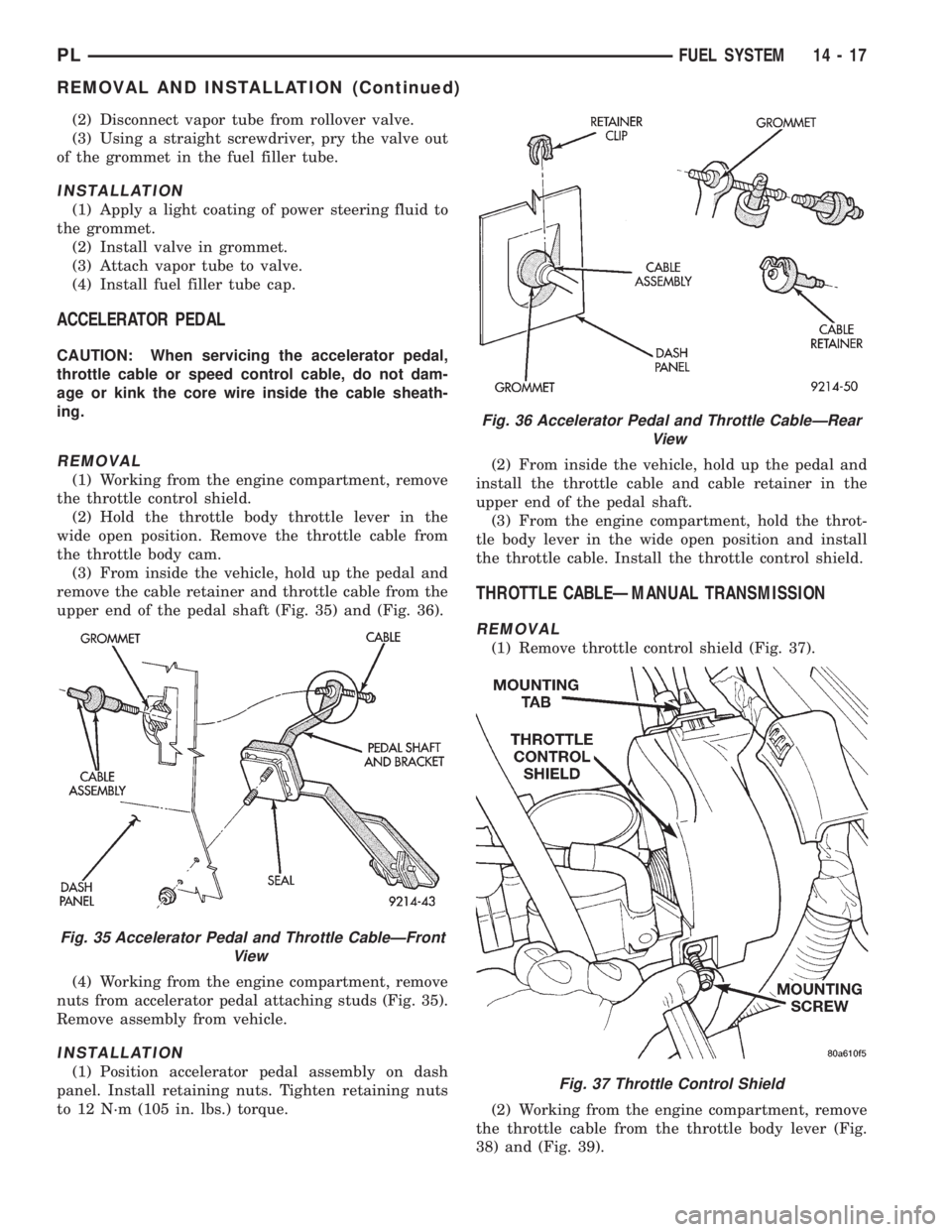
(3) From inside the vehicle, hold up the pedal and
remove the cable retainer and throttle cable from the
upper end of the pedal shaft (Fig. 35) and (Fig. 36).
(4) Working from the engine compartment, remove
nuts from accelerator pedal attaching studs (Fig. 35).
Remove assembly from vehicle.
INSTALLATION
(1) Position accelerator pedal assembly on dash
panel. Install retaining nuts. Tighten retaining nuts
to 12 N´m (105 in. lbs.) torque.(2) From inside the vehicle, hold up the pedal and
install the throttle cable and cable retainer in the
upper end of the pedal shaft.
(3) From the engine compartment, hold the throt-
tle body lever in the wide open position and install
the throttle cable. Install the throttle control shield.
THROTTLE CABLEÐMANUAL TRANSMISSION
REMOVAL
(1) Remove throttle control shield (Fig. 37).
(2) Working from the engine compartment, remove
the throttle cable from the throttle body lever (Fig.
38) and (Fig. 39).
Fig. 35 Accelerator Pedal and Throttle CableÐFront
View
Fig. 36 Accelerator Pedal and Throttle CableÐRear
View
Fig. 37 Throttle Control Shield
PLFUEL SYSTEM 14 - 17
REMOVAL AND INSTALLATION (Continued)
Page 902 of 1200
STEERING
CONTENTS
page page
GENERAL INFORMATION................... 1
POWER STEERING PUMP.................. 9STEERING COLUMN...................... 35
STEERING GEAR........................ 26
GENERAL INFORMATION
INDEX
page page
GENERAL INFORMATION
STEERING SYSTEM AND COMPONENT
DESCRIPTION......................... 1DIAGNOSIS AND TESTING
STEERING SYSTEM DIAGNOSIS CHARTS..... 2
GENERAL INFORMATION
STEERING SYSTEM AND COMPONENT
DESCRIPTION
This vehicle comes with power steering as stan-
dard equipment and is the only steering system
available.
The power steering system consists of these six
major components. Power Steering Pump, Power
Steering Gear, Power Steering Reservoir, Power
Steering Supply and Pressure Hoses, and Power
Steering Fluid Return Hose. Turning of the steering
wheel is converted into linear travel through themeshing of the helical pinion teeth with the rack
teeth. Power assist steering is provided by an open
center, rotary type control valve. It is used to direct
oil from the power steering pump to either side of the
integral steering rack piston.
Road feel is controlled by the diameter of a torsion
bar which initially steers the vehicle. As steering
effort increases as in a turn, the torsion bar twists,
causing relative rotary motion between the rotary
valve body and valve spool. This movement directs
oil behind the integral rack piston, which in turn,
builds up hydraulic pressure and assists in the turn-
ing effort.
PLSTEERING 19 - 1
Page 903 of 1200
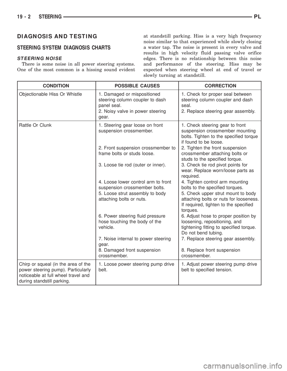
DIAGNOSIS AND TESTING
STEERING SYSTEM DIAGNOSIS CHARTS
STEERING NOISE
There is some noise in all power steering systems.
One of the most common is a hissing sound evidentat standstill parking. Hiss is a very high frequency
noise similar to that experienced while slowly closing
a water tap. The noise is present in every valve and
results in high velocity fluid passing valve orifice
edges. There is no relationship between this noise
and performance of the steering. Hiss may be
expected when steering wheel at end of travel or
slowly turning at standstill.
CONDITION POSSIBLE CAUSES CORRECTION
Objectionable Hiss Or Whistle 1. Damaged or mispositioned
steering column coupler to dash
panel seal.1. Check for proper seal between
steering column coupler and dash
seal.
2. Noisy valve in power steering
gear.2. Replace steering gear assembly.
Rattle Or Clunk 1. Steering gear loose on front
suspension crossmember.1. Check steering gear to front
suspension crossmember mounting
bolts. Tighten to the specified torque
if found to be loose.
2. Front suspension crossmember to
frame bolts or studs loose.2. Tighten the front suspension
crossmember attaching bolts or
studs to the specified torque.
3. Loose tie rod (outer or inner). 3. Check tie rod pivot points for
wear. Replace worn/loose parts as
required.
4. Loose lower control arm to front
suspension crossmember bolts.4. Tighten control arm mounting
bolts to the specified torques.
5. Loose strut assembly to body
attaching bolts or nuts.5. Check upper strut mount to body
attaching bolts or nuts for looseness.
If required, tighten to the specified
torques.
6. Power steering fluid pressure
hose touching the body of the
vehicle.6. Adjust hose to proper position by
loosening, repositioning, and
tightening fitting to specified torque.
Do not bend tubing.
7. Noise internal to power steering
gear.7. Replace steering gear assembly.
8. Damaged front suspension
crossmember.8. Replace front suspension
crossmember.
Chirp or squeal (in the area of the
power steering pump). Particularly
noticeable at full wheel travel and
during standstill parking.1. Loose power steering pump drive
belt.1. Adjust power steering pump drive
belt to specified tension.
19 - 2 STEERINGPL
Page 904 of 1200
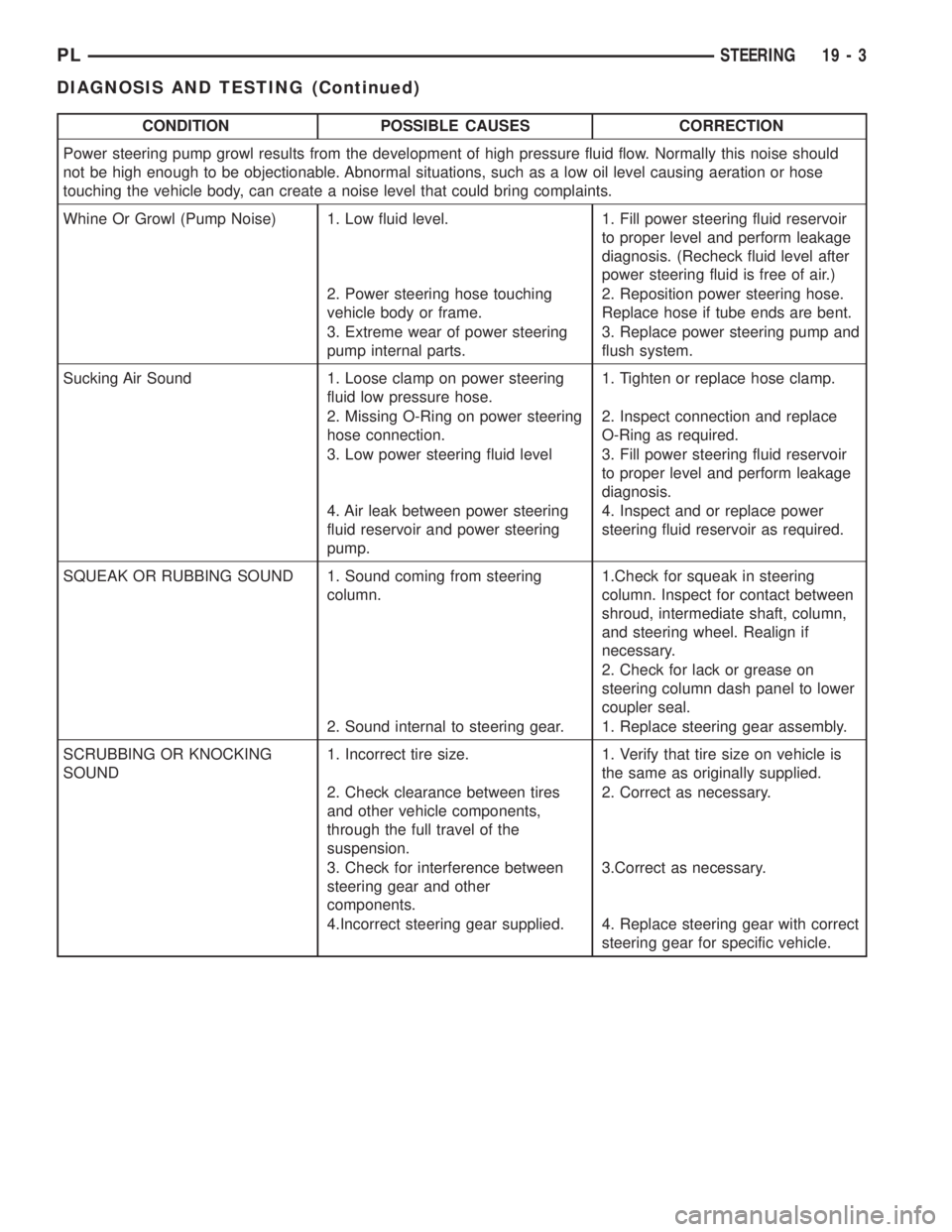
CONDITION POSSIBLE CAUSES CORRECTION
Power steering pump growl results from the development of high pressure fluid flow. Normally this noise should
not be high enough to be objectionable. Abnormal situations, such as a low oil level causing aeration or hose
touching the vehicle body, can create a noise level that could bring complaints.
Whine Or Growl (Pump Noise) 1. Low fluid level. 1. Fill power steering fluid reservoir
to proper level and perform leakage
diagnosis. (Recheck fluid level after
power steering fluid is free of air.)
2. Power steering hose touching
vehicle body or frame.2. Reposition power steering hose.
Replace hose if tube ends are bent.
3. Extreme wear of power steering
pump internal parts.3. Replace power steering pump and
flush system.
Sucking Air Sound 1. Loose clamp on power steering
fluid low pressure hose.1. Tighten or replace hose clamp.
2. Missing O-Ring on power steering
hose connection.2. Inspect connection and replace
O-Ring as required.
3. Low power steering fluid level 3. Fill power steering fluid reservoir
to proper level and perform leakage
diagnosis.
4. Air leak between power steering
fluid reservoir and power steering
pump.4. Inspect and or replace power
steering fluid reservoir as required.
SQUEAK OR RUBBING SOUND 1. Sound coming from steering
column.1.Check for squeak in steering
column. Inspect for contact between
shroud, intermediate shaft, column,
and steering wheel. Realign if
necessary.
2. Check for lack or grease on
steering column dash panel to lower
coupler seal.
2. Sound internal to steering gear. 1. Replace steering gear assembly.
SCRUBBING OR KNOCKING
SOUND1. Incorrect tire size. 1. Verify that tire size on vehicle is
the same as originally supplied.
2. Check clearance between tires
and other vehicle components,
through the full travel of the
suspension.2. Correct as necessary.
3. Check for interference between
steering gear and other
components.3.Correct as necessary.
4.Incorrect steering gear supplied. 4. Replace steering gear with correct
steering gear for specific vehicle.
PLSTEERING 19 - 3
DIAGNOSIS AND TESTING (Continued)