flat tire DODGE NEON 1999 Service Repair Manual
[x] Cancel search | Manufacturer: DODGE, Model Year: 1999, Model line: NEON, Model: DODGE NEON 1999Pages: 1200, PDF Size: 35.29 MB
Page 15 of 1200
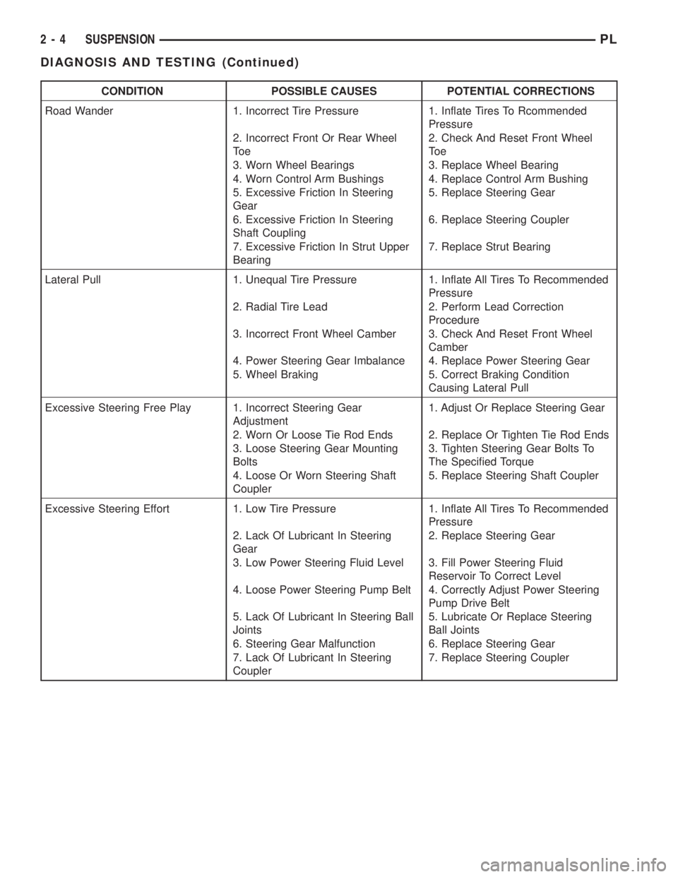
CONDITION POSSIBLE CAUSES POTENTIAL CORRECTIONS
Road Wander 1. Incorrect Tire Pressure 1. Inflate Tires To Rcommended
Pressure
2. Incorrect Front Or Rear Wheel
To e2. Check And Reset Front Wheel
To e
3. Worn Wheel Bearings 3. Replace Wheel Bearing
4. Worn Control Arm Bushings 4. Replace Control Arm Bushing
5. Excessive Friction In Steering
Gear5. Replace Steering Gear
6. Excessive Friction In Steering
Shaft Coupling6. Replace Steering Coupler
7. Excessive Friction In Strut Upper
Bearing7. Replace Strut Bearing
Lateral Pull 1. Unequal Tire Pressure 1. Inflate All Tires To Recommended
Pressure
2. Radial Tire Lead 2. Perform Lead Correction
Procedure
3. Incorrect Front Wheel Camber 3. Check And Reset Front Wheel
Camber
4. Power Steering Gear Imbalance 4. Replace Power Steering Gear
5. Wheel Braking 5. Correct Braking Condition
Causing Lateral Pull
Excessive Steering Free Play 1. Incorrect Steering Gear
Adjustment1. Adjust Or Replace Steering Gear
2. Worn Or Loose Tie Rod Ends 2. Replace Or Tighten Tie Rod Ends
3. Loose Steering Gear Mounting
Bolts3. Tighten Steering Gear Bolts To
The Specified Torque
4. Loose Or Worn Steering Shaft
Coupler5. Replace Steering Shaft Coupler
Excessive Steering Effort 1. Low Tire Pressure 1. Inflate All Tires To Recommended
Pressure
2. Lack Of Lubricant In Steering
Gear2. Replace Steering Gear
3. Low Power Steering Fluid Level 3. Fill Power Steering Fluid
Reservoir To Correct Level
4. Loose Power Steering Pump Belt 4. Correctly Adjust Power Steering
Pump Drive Belt
5. Lack Of Lubricant In Steering Ball
Joints5. Lubricate Or Replace Steering
Ball Joints
6. Steering Gear Malfunction 6. Replace Steering Gear
7. Lack Of Lubricant In Steering
Coupler7. Replace Steering Coupler
2 - 4 SUSPENSIONPL
DIAGNOSIS AND TESTING (Continued)
Page 16 of 1200
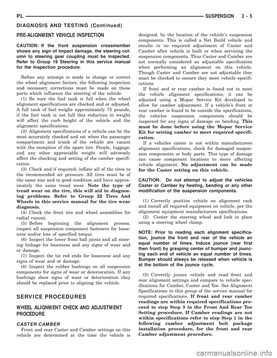
PRE-ALIGNMENT VEHICLE INSPECTION
CAUTION: If the front suspension crossmember
shows any sign of impact damage, the steering col-
umn to steering gear coupling must be inspected.
Refer to Group 19 Steering in this service manual
for the inspection procedure.
Before any attempt is made to change or correct
the wheel alignment factors, the following inspection
and necessary corrections must be made on those
parts which influence the steering of the vehicle.
(1) Be sure the fuel tank is full when the wheel
alignment specifications are checked and or adjusted.
A full tank of fuel weighs approximately 75 pounds,
if the fuel tank is not full this reduction in weight
will affect the curb height of the vehicle and the
alignment specifications.
(2) Alignment specifications of a vehicle can be the
most accurately checked and set when the passenger
compartment and trunk of the vehicle are vacant
with the exception of the spare tire. People, luggage,
and any other appreciable weight will adversely
affect the checking and setting of the camber specifi-
cation.
(3) Check and if required, inflate all of the tires to
the recommended air pressure. All tires must be of
the same size and in good condition and have approx-
imately the same tread wear.Note the type of
tread wear on the tire, this will aid in diagnos-
ing problems. Refer to Group 22 Tires And
Wheels in this service manual for the tire wear
diagnosis.
(4) Check the front tire and wheel assemblies for
radial runout.
(5) Before beginning the alignment process,
inspect all suspension component fasteners for loose-
ness and/or loss of specified torque.
(6) Inspect the lower front ball joints and all steer-
ing linkage for looseness and any signs of wear and
or damage.
(7) Inspect the tie rod ends for looseness and any
signs of wear and or damage.
(8) Inspect the rubber bushings on all suspension
components for signs of wear or deterioration. If any
bushings show signs of wear or deterioration they
should be replaced prior to aligning the vehicle.
SERVICE PROCEDURES
WHEEL ALIGNMENT CHECK AND ADJUSTMENT
PROCEDURE
CASTER CAMBER
Front and rear Caster and Camber settings on this
vehicle are determined at the time the vehicle isdesigned, by the location of the vehicle's suspension
components. This is called a Net Build vehicle and
results in no required adjustment of Caster and
Camber after vehicle is built or when servicing the
suspension components. Thus Caster and Camber are
not normally considered an adjustable specification
when performing an alignment on this vehicle.
Though Caster and Camber are not adjustable they
must be checked to ensure they meet vehicle specifi-
cations.
If front and or rear camber is found not to meet
the vehicle alignment specifications, it can be
adjusted using a Mopar Service Kit developed to
allow for camber adjustment. If a vehicle's front or
rear camber is found to be outside the specifications,
the vehicles suspension components should be
inspected for any signs of damage on bending.This
must be done before using the Mopar Service
Kit for setting camber to meet required specifi-
cation.
If a vehicles caster is not within manufacturers
alignment specifications, check for damaged suspen-
sion components or body parts. This type of damage
can cause component locations to move affecting
vehicle alignment.No adjustment can be made
for the Caster setting on this vehicle.
CAUTION: Do not attempt to adjust the vehicles
Caster or Camber by heating, bending or any other
modification of the suspension components.
(1) Correctly position vehicle on alignment rack
and install all required equipment on vehicle, per the
alignment equipment manufacturers specifications.
(2) Center the steering wheel and lock in place
using a steering wheel clamp.
NOTE: Prior to reading each alignment specifica-
tion, jounce the front and rear of the vehicle an
equal number of times. Induce jounce (rear first
then front) by grasping center of bumper and jounc-
ing each end of vehicle an equal number of times.
Bumper should always be released when vehicle is
at the bottom of the jounce cycle.
(3) Correctly jounce vehicle and read front and
rear alignment settings and compare to vehicle spec-
ifications for Camber, Caster and Toe. See Alignment
Specifications in this group of the service manual for
required specifications.If front and rear camber
readings are within required specifications pro-
ceed to step Step 3 in the Front And Rear Toe
Setting procedure. If Camber readings are not
within specifications refer to step Step 1 in the
following camber adjustment bolt package
installation procedure, for the front and rear
Camber adjustment procedure.
PLSUSPENSION 2 - 5
DIAGNOSIS AND TESTING (Continued)
Page 59 of 1200
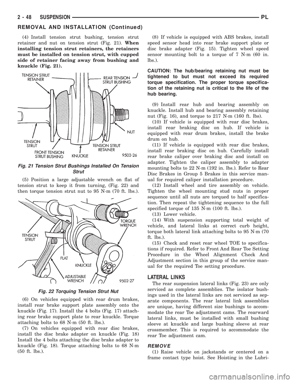
(4) Install tension strut bushing, tension strut
retainer and nut on tension strut (Fig. 21).When
installing tension strut retainers, the retainers
must be installed on tension strut, with cupped
side of retainer facing away from bushing and
knuckle (Fig. 21).
(5) Position a large adjustable wrench on flat of
tension strut to keep it from turning, (Fig. 22) and
then torque tension strut nut to 95 N´m (70 ft. lbs.).
(6) On vehicles equipped with rear drum brakes,
install rear brake support plate assembly onto the
knuckle (Fig. 17). Install the 4 bolts (Fig. 17) attach-
ing rear brake support plate to rear knuckle. Torque
attaching bolts to 68 N´m (50 ft. lbs.).
(7) On vehicles equipped with rear disc brakes,
install the disc brake adapter on knuckle (Fig. 18)
Install the 4 bolts attaching the disc brake adapter to
knuckle (Fig. 18). Torque attaching bolts to 68 N´m
(50 ft. lbs.).(8) If vehicle is equipped with ABS brakes, install
speed sensor head into rear brake support plate or
disc brake adapter (Fig. 15). Tighten wheel speed
sensor mounting bolt to a torque of 7 N´m (60 in.
lbs.).
CAUTION: The hub/bearing retaining nut must be
tightened to but must not exceed its required
torque specification. The proper torque specifica-
tion of the retaining nut is critical to the life of the
hub bearing.
(9) Install rear hub and bearing assembly on
knuckle. Install hub and bearing assembly retaining
nut (Fig. 16), and torque to 217 N´m (160 ft. lbs).
(10) If vehicle is equipped with rear disc brakes,
install rear braking disc on hub. If vehicle is
equipped with rear drum brakes, install the brake
drum on hub.
(11) If vehicle is equipped with rear disc brakes,
install rear braking disc on hub. Carefully install
rear brake caliper over braking disc and install on
adapter. Tighten the caliper assembly to adapter
mounting bolts to 22 N´m (192 in. lbs.). Refer to Rear
Disc Brakes in Group 5 Brakes in this service man-
ual for required caliper installation procedure.
(12) Install wheel and tire assembly on vehicle.
Tighten the wheel mounting stud nuts in proper
sequence until all nuts are torqued to half specifica-
tion. Then repeat the tightening sequence to the full
specified torque of 135 N´m (100 ft. lbs.).
(13) Lower vehicle.
(14) With suspension supporting total weight of
vehicle, and lateral links at correct curb height,
torque both lateral link attaching bolts to 95 N´m (70
ft. lbs.).
(15) Check and reset rear wheel TOE to specifica-
tions if required. Refer to Front And Rear Toe Setting
Procedure in the Wheel Alignment Check And
Adjustment section in this group of the service man-
ual for the required Toe setting procedure.
LATERAL LINKS
The rear suspension lateral links (Fig. 23) are only
serviced as complete assemblies. The isolator bush-
ings used in the lateral links are not serviced as sep-
arate components. The rear lateral link assemblies
are unique, having different size bushings to accom-
modate the rear Toe adjustment cams. The rearward
lateral links, must be installed with small bushing
sleeve at knuckle and large bushing sleeve at rear
crossmember. This is required to accommodate the
rear Toe adjustment cam.
REMOVE
(1) Raise vehicle on jackstands or centered on a
frame contact type hoist. See Hoisting in the Lubri-
Fig. 21 Tension Strut Bushings Installed On Tension
Strut
Fig. 22 Torquing Tension Strut Nut
2 - 48 SUSPENSIONPL
REMOVAL AND INSTALLATION (Continued)
Page 144 of 1200
MUST always be used when installing brake
hose to caliper.
(12) Bleed the brake system (see Bleeding Brake
System).
WHEEL CYLINDER (REAR DRUM BRAKE)
DISASSEMBLE
To disassemble the wheel cylinders, proceed as fol-
lows:
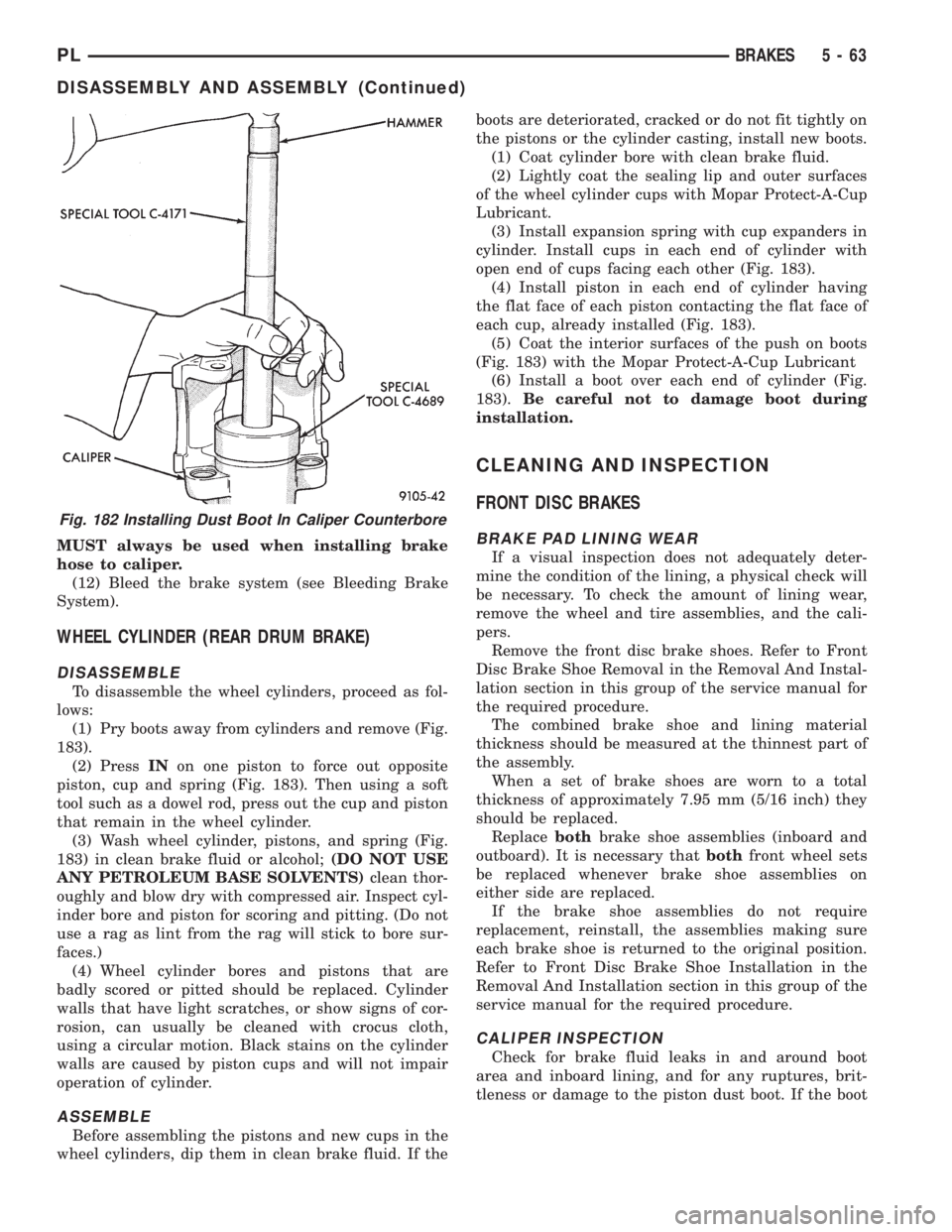
(1) Pry boots away from cylinders and remove (Fig.
183).
(2) PressINon one piston to force out opposite
piston, cup and spring (Fig. 183). Then using a soft
tool such as a dowel rod, press out the cup and piston
that remain in the wheel cylinder.
(3) Wash wheel cylinder, pistons, and spring (Fig.
183) in clean brake fluid or alcohol;(DO NOT USE
ANY PETROLEUM BASE SOLVENTS)clean thor-
oughly and blow dry with compressed air. Inspect cyl-
inder bore and piston for scoring and pitting. (Do not
use a rag as lint from the rag will stick to bore sur-
faces.)
(4) Wheel cylinder bores and pistons that are
badly scored or pitted should be replaced. Cylinder
walls that have light scratches, or show signs of cor-
rosion, can usually be cleaned with crocus cloth,
using a circular motion. Black stains on the cylinder
walls are caused by piston cups and will not impair
operation of cylinder.
ASSEMBLE
Before assembling the pistons and new cups in the
wheel cylinders, dip them in clean brake fluid. If theboots are deteriorated, cracked or do not fit tightly on
the pistons or the cylinder casting, install new boots.
(1) Coat cylinder bore with clean brake fluid.
(2) Lightly coat the sealing lip and outer surfaces
of the wheel cylinder cups with Mopar Protect-A-Cup
Lubricant.
(3) Install expansion spring with cup expanders in
cylinder. Install cups in each end of cylinder with
open end of cups facing each other (Fig. 183).
(4) Install piston in each end of cylinder having
the flat face of each piston contacting the flat face of
each cup, already installed (Fig. 183).
(5) Coat the interior surfaces of the push on boots
(Fig. 183) with the Mopar Protect-A-Cup Lubricant
(6) Install a boot over each end of cylinder (Fig.
183).Be careful not to damage boot during
installation.
CLEANING AND INSPECTION
FRONT DISC BRAKES
BRAKE PAD LINING WEAR
If a visual inspection does not adequately deter-
mine the condition of the lining, a physical check will
be necessary. To check the amount of lining wear,
remove the wheel and tire assemblies, and the cali-
pers.
Remove the front disc brake shoes. Refer to Front
Disc Brake Shoe Removal in the Removal And Instal-
lation section in this group of the service manual for
the required procedure.
The combined brake shoe and lining material
thickness should be measured at the thinnest part of
the assembly.
When a set of brake shoes are worn to a total
thickness of approximately 7.95 mm (5/16 inch) they
should be replaced.
Replacebothbrake shoe assemblies (inboard and
outboard). It is necessary thatbothfront wheel sets
be replaced whenever brake shoe assemblies on
either side are replaced.
If the brake shoe assemblies do not require
replacement, reinstall, the assemblies making sure
each brake shoe is returned to the original position.
Refer to Front Disc Brake Shoe Installation in the
Removal And Installation section in this group of the
service manual for the required procedure.
CALIPER INSPECTION
Check for brake fluid leaks in and around boot
area and inboard lining, and for any ruptures, brit-
tleness or damage to the piston dust boot. If the boot
Fig. 182 Installing Dust Boot In Caliper Counterbore
PLBRAKES 5 - 63
DISASSEMBLY AND ASSEMBLY (Continued)
Page 333 of 1200
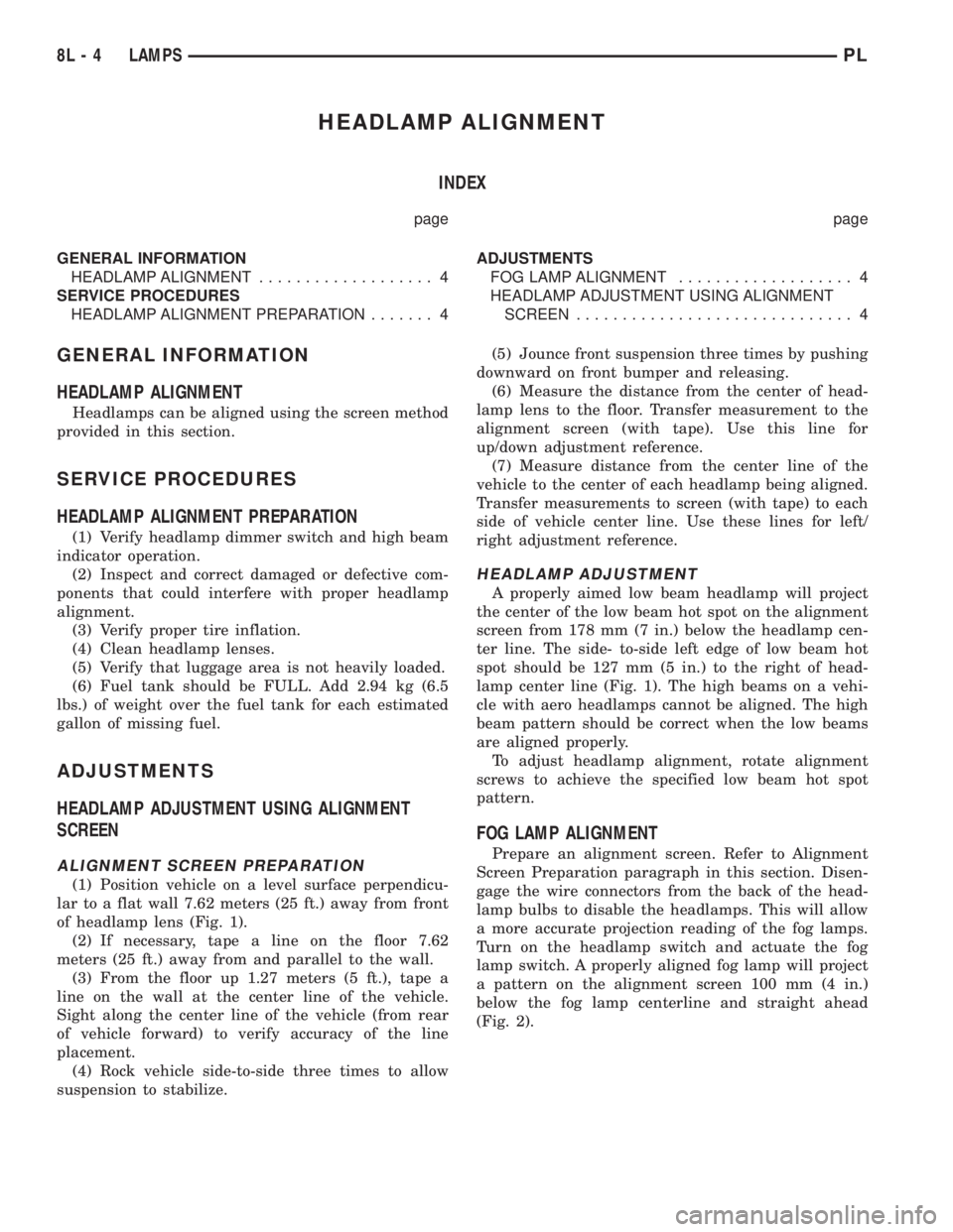
HEADLAMP ALIGNMENT
INDEX
page page
GENERAL INFORMATION
HEADLAMP ALIGNMENT................... 4
SERVICE PROCEDURES
HEADLAMP ALIGNMENT PREPARATION....... 4ADJUSTMENTS
FOG LAMP ALIGNMENT................... 4
HEADLAMP ADJUSTMENT USING ALIGNMENT
SCREEN.............................. 4
GENERAL INFORMATION
HEADLAMP ALIGNMENT
Headlamps can be aligned using the screen method
provided in this section.
SERVICE PROCEDURES
HEADLAMP ALIGNMENT PREPARATION
(1) Verify headlamp dimmer switch and high beam
indicator operation.
(2) Inspect and correct damaged or defective com-
ponents that could interfere with proper headlamp
alignment.
(3) Verify proper tire inflation.
(4) Clean headlamp lenses.
(5) Verify that luggage area is not heavily loaded.
(6) Fuel tank should be FULL. Add 2.94 kg (6.5
lbs.) of weight over the fuel tank for each estimated
gallon of missing fuel.
ADJUSTMENTS
HEADLAMP ADJUSTMENT USING ALIGNMENT
SCREEN
ALIGNMENT SCREEN PREPARATION
(1) Position vehicle on a level surface perpendicu-
lar to a flat wall 7.62 meters (25 ft.) away from front
of headlamp lens (Fig. 1).
(2) If necessary, tape a line on the floor 7.62
meters (25 ft.) away from and parallel to the wall.
(3) From the floor up 1.27 meters (5 ft.), tape a
line on the wall at the center line of the vehicle.
Sight along the center line of the vehicle (from rear
of vehicle forward) to verify accuracy of the line
placement.
(4) Rock vehicle side-to-side three times to allow
suspension to stabilize.(5) Jounce front suspension three times by pushing
downward on front bumper and releasing.
(6) Measure the distance from the center of head-
lamp lens to the floor. Transfer measurement to the
alignment screen (with tape). Use this line for
up/down adjustment reference.
(7) Measure distance from the center line of the
vehicle to the center of each headlamp being aligned.
Transfer measurements to screen (with tape) to each
side of vehicle center line. Use these lines for left/
right adjustment reference.
HEADLAMP ADJUSTMENT
A properly aimed low beam headlamp will project
the center of the low beam hot spot on the alignment
screen from 178 mm (7 in.) below the headlamp cen-
ter line. The side- to-side left edge of low beam hot
spot should be 127 mm (5 in.) to the right of head-
lamp center line (Fig. 1). The high beams on a vehi-
cle with aero headlamps cannot be aligned. The high
beam pattern should be correct when the low beams
are aligned properly.
To adjust headlamp alignment, rotate alignment
screws to achieve the specified low beam hot spot
pattern.
FOG LAMP ALIGNMENT
Prepare an alignment screen. Refer to Alignment
Screen Preparation paragraph in this section. Disen-
gage the wire connectors from the back of the head-
lamp bulbs to disable the headlamps. This will allow
a more accurate projection reading of the fog lamps.
Turn on the headlamp switch and actuate the fog
lamp switch. A properly aligned fog lamp will project
a pattern on the alignment screen 100 mm (4 in.)
below the fog lamp centerline and straight ahead
(Fig. 2).
8L - 4 LAMPSPL
Page 717 of 1200
²When checking #3 main bearing shim #2 & #4
main bearing.
²When checking #4 main bearing shim #3 main
bearing.
NOTE: REMOVE ALL SHIMS BEFORE REASSEM-
BLING ENGINE
ALTERNATIVE METHOD
The weight of the crankshaft can be supported by a
jack under the counterweight adjacent to the bearing
being checked.
PLASTIGAGE PROCEDURE
(1) Remove oil film from surface to be checked.
Plastigage is soluble in oil.
(2) Place a piece of Plastigage across the entire
width of the bearing shell in the cap approximately
6.35 mm (1/4 in.) off center and away from the oil
holes (Fig. 3). (In addition, suspected areas can be
checked by placing the Plastigage in the suspected
area). Torque the bearing cap bolts of the bearing
being checked to the proper specifications.
(3) Remove the bearing cap and compare the
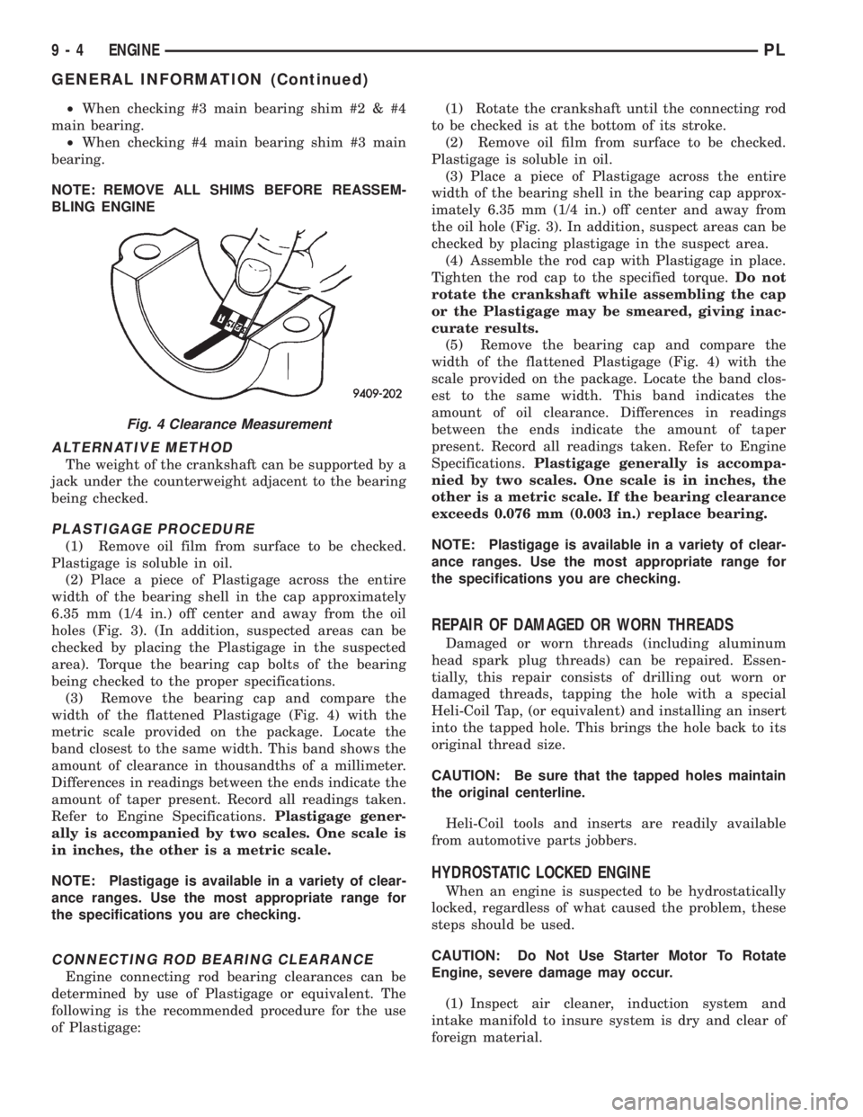
width of the flattened Plastigage (Fig. 4) with the
metric scale provided on the package. Locate the
band closest to the same width. This band shows the
amount of clearance in thousandths of a millimeter.
Differences in readings between the ends indicate the
amount of taper present. Record all readings taken.
Refer to Engine Specifications.Plastigage gener-
ally is accompanied by two scales. One scale is
in inches, the other is a metric scale.
NOTE: Plastigage is available in a variety of clear-
ance ranges. Use the most appropriate range for
the specifications you are checking.
CONNECTING ROD BEARING CLEARANCE
Engine connecting rod bearing clearances can be
determined by use of Plastigage or equivalent. The
following is the recommended procedure for the use
of Plastigage:(1) Rotate the crankshaft until the connecting rod
to be checked is at the bottom of its stroke.
(2) Remove oil film from surface to be checked.
Plastigage is soluble in oil.
(3) Place a piece of Plastigage across the entire
width of the bearing shell in the bearing cap approx-
imately 6.35 mm (1/4 in.) off center and away from
the oil hole (Fig. 3). In addition, suspect areas can be
checked by placing plastigage in the suspect area.
(4) Assemble the rod cap with Plastigage in place.
Tighten the rod cap to the specified torque.Do not
rotate the crankshaft while assembling the cap
or the Plastigage may be smeared, giving inac-
curate results.
(5) Remove the bearing cap and compare the
width of the flattened Plastigage (Fig. 4) with the
scale provided on the package. Locate the band clos-
est to the same width. This band indicates the
amount of oil clearance. Differences in readings
between the ends indicate the amount of taper
present. Record all readings taken. Refer to Engine
Specifications.Plastigage generally is accompa-
nied by two scales. One scale is in inches, the
other is a metric scale. If the bearing clearance
exceeds 0.076 mm (0.003 in.) replace bearing.
NOTE: Plastigage is available in a variety of clear-
ance ranges. Use the most appropriate range for
the specifications you are checking.
REPAIR OF DAMAGED OR WORN THREADS
Damaged or worn threads (including aluminum
head spark plug threads) can be repaired. Essen-
tially, this repair consists of drilling out worn or
damaged threads, tapping the hole with a special
Heli-Coil Tap, (or equivalent) and installing an insert
into the tapped hole. This brings the hole back to its
original thread size.
CAUTION: Be sure that the tapped holes maintain
the original centerline.
Heli-Coil tools and inserts are readily available
from automotive parts jobbers.
HYDROSTATIC LOCKED ENGINE
When an engine is suspected to be hydrostatically
locked, regardless of what caused the problem, these
steps should be used.
CAUTION: Do Not Use Starter Motor To Rotate
Engine, severe damage may occur.
(1) Inspect air cleaner, induction system and
intake manifold to insure system is dry and clear of
foreign material.
Fig. 4 Clearance Measurement
9 - 4 ENGINEPL
GENERAL INFORMATION (Continued)
Page 734 of 1200
(8) Install A/C compressor and hoses. Refer to
Group 24, Heater and Air Conditioning for procedure.
(9) Install accessory drive belts. Refer to Group 7,
Cooling System Accessory Drive Section for belt ten-
sion adjustment.
(10) Install front engine mount. Refer to this sec-
tion for procedure.
(11) Manual transmission: Install power hop
damper.
(12) Install inner splash shield. Install wheels and
tires.
(13)Manual Transmission:Connect clutch cable
and linkages. Refer to Group 6, Manual Transaxle
Clutch.
(14)Automatic Transmission:Connect shifter
and kickdown linkage. Refer to Group 21, Transaxle
for procedures.
(15) Connect fuel line and heater hoses.
(16) Install ground straps. Connect engine and
throttle body connections and harnesses. Refer to
Group 8, Electrical for procedure.
(17) Connect throttle body linkage. Refer to Group
14, Fuel System for procedure.
(18) Install radiator and shroud assembly. Install
radiator hoses. Fill cooling system. Refer to Group 7,
Cooling System for filling procedure.
(19) Install battery tray and battery. Set Power-
train Control Module (PCM) into place.
(20) Install air cleaner and hoses.
(21) Install oil filter. Fill engine crankcase with
proper oil to correct level.
(22) Perform camshaft and crankshaft timing
relearn procedure as follows:
²Connect the DRB scan tool to the data link
(diagnostic) connector. This connector is located in
the passenger compartment; at the lower edge of
instrument panel; near the steering column.
²Turn the ignition switch on and access the ªmis-
cellaneousº screen.
²Select ªre-learn cam/crankº option and follow
directions on DRB screen.
(23) Start engine and run until operating temper-
ature is reached.
(24) Adjust transmission linkage, if necessary.
CYLINDER HEAD COVER
REMOVAL
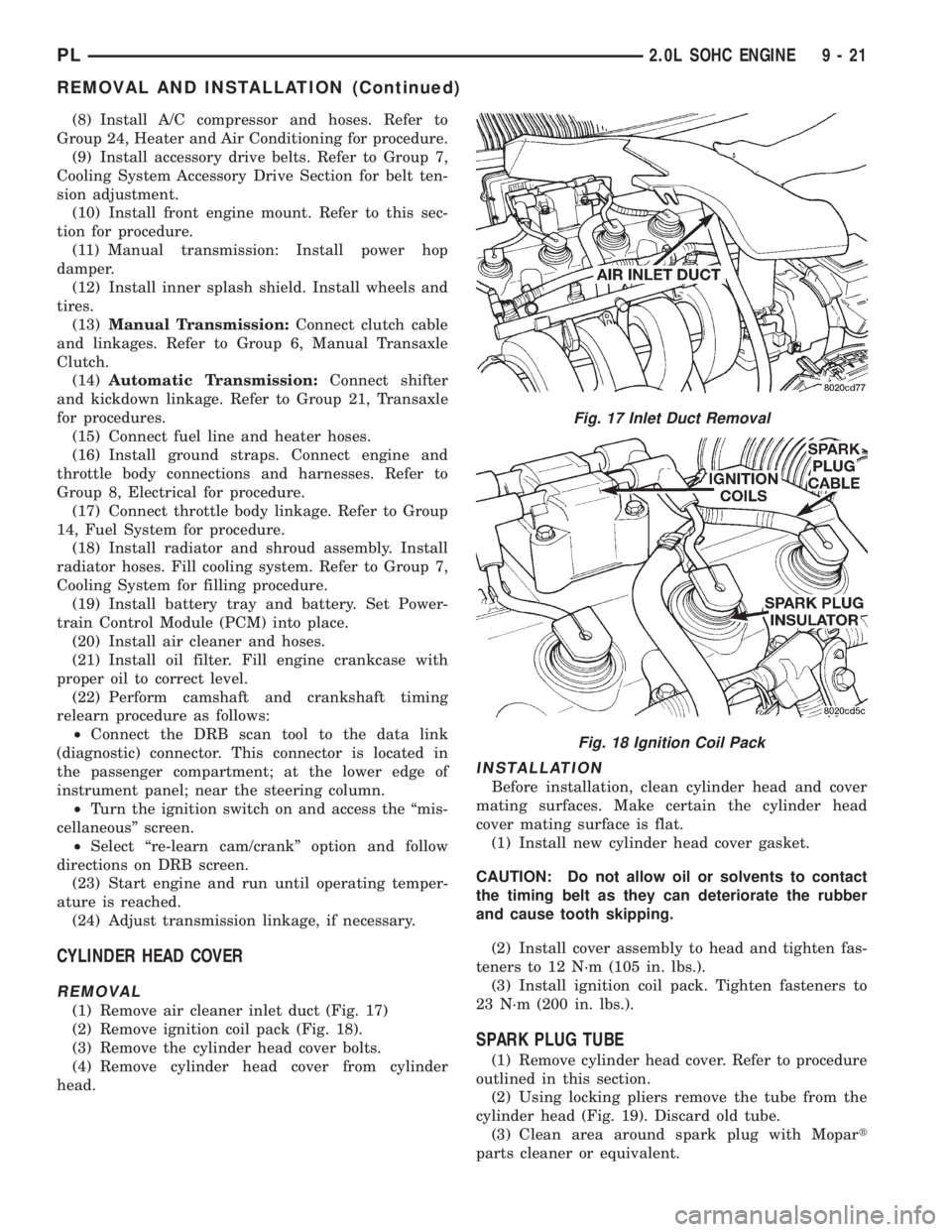
(1) Remove air cleaner inlet duct (Fig. 17)
(2) Remove ignition coil pack (Fig. 18).
(3) Remove the cylinder head cover bolts.
(4) Remove cylinder head cover from cylinder
head.
INSTALLATION
Before installation, clean cylinder head and cover
mating surfaces. Make certain the cylinder head
cover mating surface is flat.
(1) Install new cylinder head cover gasket.
CAUTION: Do not allow oil or solvents to contact
the timing belt as they can deteriorate the rubber
and cause tooth skipping.
(2) Install cover assembly to head and tighten fas-
teners to 12 N´m (105 in. lbs.).
(3) Install ignition coil pack. Tighten fasteners to
23 N´m (200 in. lbs.).
SPARK PLUG TUBE
(1) Remove cylinder head cover. Refer to procedure
outlined in this section.
(2) Using locking pliers remove the tube from the
cylinder head (Fig. 19). Discard old tube.
(3) Clean area around spark plug with Mopart
parts cleaner or equivalent.
Fig. 17 Inlet Duct Removal
Fig. 18 Ignition Coil Pack
PL2.0L SOHC ENGINE 9 - 21
REMOVAL AND INSTALLATION (Continued)
Page 905 of 1200
BINDING STICKING SEIZED
SHAKE SHUDDER VIBRATION
CONDITION POSSIBLE CAUSES CORRECTION
CATCHES, STICKS IN CERTAIN
POSITIONS OR IS DIFFICULT TO
TURN.1. Low power steering fluid level. 1. Fill power steering fluid reservoir
to specified level and perform
leakage diagnosis.
2. Tires not inflated to specified
pressure.2. Inflate tires to the specified
pressure.
3. Lack of lubrication in front
suspension control arm ball joints.3. Lubricate ball joints if ball joints
are not a lubricated for life type ball
joint. If ball joint is a lubricated for
life ball joint, replace ball joint or
control arm.
4. Lack of lubrication in front
suspension outer tie rod ends.4. Lubricate tie rod ends if they are
not a lubricated for life type. If tie rod
end is a lubricated for life type,
replace tie rod end.
5. Loose power steering pump drive
belt.5. Tighten the power steering pump
drive belt to the specified tension.
See accessory drive in service
manual.
6. Faulty power steering pump flow
control. (Verify cause using Power
Steering Pump Test Procedure.)6. Replace power steering pump.
7. Excessive friction in steering
column or intermediate shaft.7. Correct condition. (See Steering
Column Service Procedure)
8. Steering column coupler binding. 8. Realign the steering column to
eliminate the binding condition.
9. Binding upper strut bearing. 9. Correct binding condition in strut
bearing.
10 Excessive friction in steering
gear.10 Replace steering gear assembly.
CONDITION POSSIBLE CAUSES CORRECTION
VIBRATION OF THE STEERING
WHEEL AND/OR DASH DURING
DRY PARK OR LOW SPEED
STEERING MANEUVERS.1. Air in the fluid of the power
steering system.1. Steering shudder can be expected
in new vehicles and vehicles with
recent steering system repairs.
Shudder should improve after the
vehicle has been driven several
weeks.
2. Tires not properly inflated. 2. Inflate tires to the specified
pressure.
3. Excessive engine vibration. 3. Ensure that the engine is running
properly.
4. Loose tie rod end. 4. Check that the inner to outer tie
rod jam nut for is tight. If required,
tighten the jam nut to the specified
torque.
5.Overcharged air conditioning
system.5.Check air conditioning pump head
pressure. (See Air Conditioning
Refrigerant System Diagnosis)
19 - 4 STEERINGPL
DIAGNOSIS AND TESTING (Continued)
Page 906 of 1200
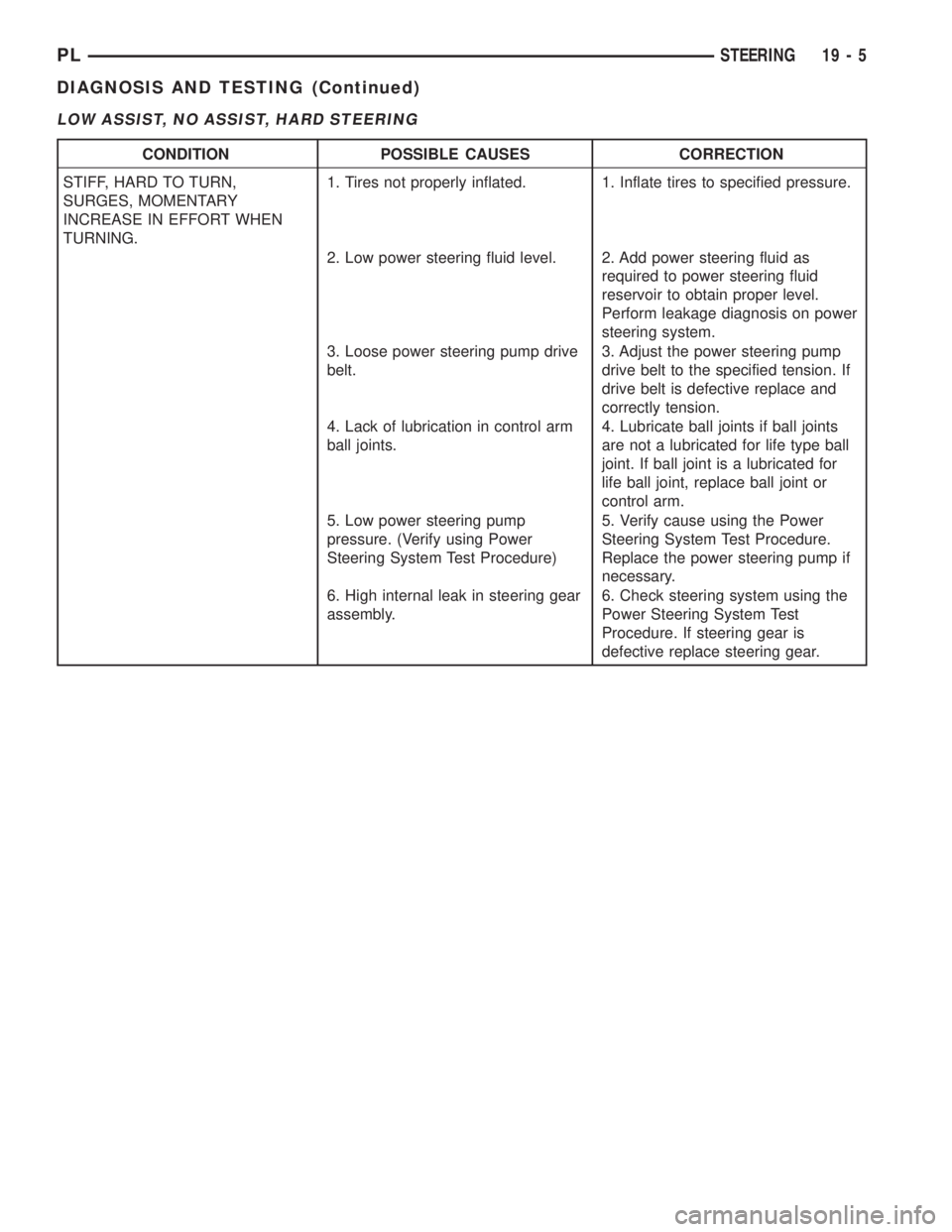
LOW ASSIST, NO ASSIST, HARD STEERING
CONDITION POSSIBLE CAUSES CORRECTION
STIFF, HARD TO TURN,
SURGES, MOMENTARY
INCREASE IN EFFORT WHEN
TURNING.1. Tires not properly inflated. 1. Inflate tires to specified pressure.
2. Low power steering fluid level. 2. Add power steering fluid as
required to power steering fluid
reservoir to obtain proper level.
Perform leakage diagnosis on power
steering system.
3. Loose power steering pump drive
belt.3. Adjust the power steering pump
drive belt to the specified tension. If
drive belt is defective replace and
correctly tension.
4. Lack of lubrication in control arm
ball joints.4. Lubricate ball joints if ball joints
are not a lubricated for life type ball
joint. If ball joint is a lubricated for
life ball joint, replace ball joint or
control arm.
5. Low power steering pump
pressure. (Verify using Power
Steering System Test Procedure)5. Verify cause using the Power
Steering System Test Procedure.
Replace the power steering pump if
necessary.
6. High internal leak in steering gear
assembly.6. Check steering system using the
Power Steering System Test
Procedure. If steering gear is
defective replace steering gear.
PLSTEERING 19 - 5
DIAGNOSIS AND TESTING (Continued)
Page 907 of 1200
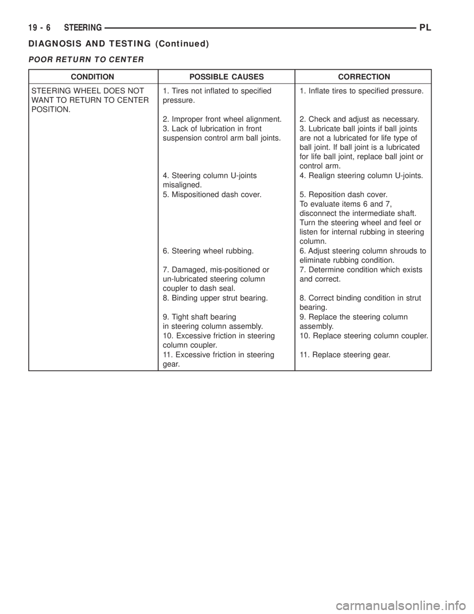
POOR RETURN TO CENTER
CONDITION POSSIBLE CAUSES CORRECTION
STEERING WHEEL DOES NOT
WANT TO RETURN TO CENTER
POSITION.1. Tires not inflated to specified
pressure.1. Inflate tires to specified pressure.
2. Improper front wheel alignment. 2. Check and adjust as necessary.
3. Lack of lubrication in front
suspension control arm ball joints.3. Lubricate ball joints if ball joints
are not a lubricated for life type of
ball joint. If ball joint is a lubricated
for life ball joint, replace ball joint or
control arm.
4. Steering column U-joints
misaligned.4. Realign steering column U-joints.
5. Mispositioned dash cover. 5. Reposition dash cover.
To evaluate items 6 and 7,
disconnect the intermediate shaft.
Turn the steering wheel and feel or
listen for internal rubbing in steering
column.
6. Steering wheel rubbing. 6. Adjust steering column shrouds to
eliminate rubbing condition.
7. Damaged, mis-positioned or
un-lubricated steering column
coupler to dash seal.7. Determine condition which exists
and correct.
8. Binding upper strut bearing. 8. Correct binding condition in strut
bearing.
9. Tight shaft bearing
in steering column assembly.9. Replace the steering column
assembly.
10. Excessive friction in steering
column coupler.10. Replace steering column coupler.
11. Excessive friction in steering
gear.11. Replace steering gear.
19 - 6 STEERINGPL
DIAGNOSIS AND TESTING (Continued)