fuse box location DODGE NEON 1999 Service Repair Manual
[x] Cancel search | Manufacturer: DODGE, Model Year: 1999, Model line: NEON, Model: DODGE NEON 1999Pages: 1200, PDF Size: 35.29 MB
Page 655 of 1200

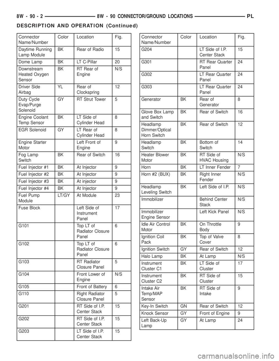
Connector
Name/NumberColor Location Fig.
Daytime Running
Lamp ModuleBK Rear of Radio 15
Dome Lamp BK LT C-Pillar 20
Downstream
Heated Oxygen
SensorBK RT Rear of
EngineN/S
Driver Side
AirbagYL Rear of
Clockspring12
Duty Cycle
Evap/Purge
SolenoidGY RT Strut Tower 5
Engine Coolant
Temp SensorBK LT Side of
Cylinder Head8
EGR Solenoid GY LT Rear of
Cylinder Head8
Engine Starter
MotorLeft Front of
Engine9
Fog Lamp
SwitchBK Rear of Switch 16
Fuel Injector #1 BK At Injector 9
Fuel Injector #2 BK At Injector 9
Fuel Injector #3 BK At injector 9
Fuel Injector #4 BK At Injector 9
Fuel Pump
ModuleLT/GY At Module 23
Fuse Block Left Side of
Instrument
Panel17
G101 Top LT of
Radiator Closure
Panel6
G102 Top LT of
Radiator Closure
Panel6
G103 RT Radiator
Closure Panel5
G104 Front Lower of
EngineN/S
G105 Front of Battery 6
G110 Right Radiator
Closure Panel5
G201 RT Side of I.P.
Center Stack15
G202 RT Side of I.P.
Center Stack15
G203 LT Side of I.P.
Center Stack15
Connector
Name/NumberColor Location Fig.
G204 LT Side of I.P.
Center Stack15
G301 RT Rear Quarter
Panel24
G302 LT Rear Quarter
Panel24
G303 LT Rear Quarter
Panel24
Generator BK Rear of
Generator8
Glove Box Lamp
and SwitchBK Rear of Switch 16
Headlamp
Dimmer/Optical
Horn SwitchBK Rear of Switch 12
Headlamp
SwitchBK Bottom of
Switch14
Heater Blower
MotorBK RT Side of
HVAC HousingN/S
Horn BK LT Inner Fender 7
Horn #2 (BUX) BK Right Inner
FenderN/S
Headlamp
Leveling SwitchBK Left Side of I.P. N/S
Immobilizer Behind Center
StackN/S
Immobilizer
Engine SensorLeft Kick Panel N/S
Idle Air Control
MotorBK On Throttle
Body9
Ignition Coil
PackBK Top of Valve
Cover8
Ignition Switch GY Rear of Switch 12
Halo Lamp BK At Lamp N/S
Instrument
Cluster C1BK LT Side of
Cluster17
Instrument
Cluster C2BK RT Side of
Cluster15
Intake Air
Temp/MAP
SensorBK RT Side of
Intake9
Key-In Switch GN Rear of Switch 12
Knock Sensor GY Front of Engine 9
Left Back-Up
LampGY At Lamp 24
8W - 90 - 2 8W - 90 CONNECTOR/GROUND LOCATIONSPL
DESCRIPTION AND OPERATION (Continued)
Page 677 of 1200

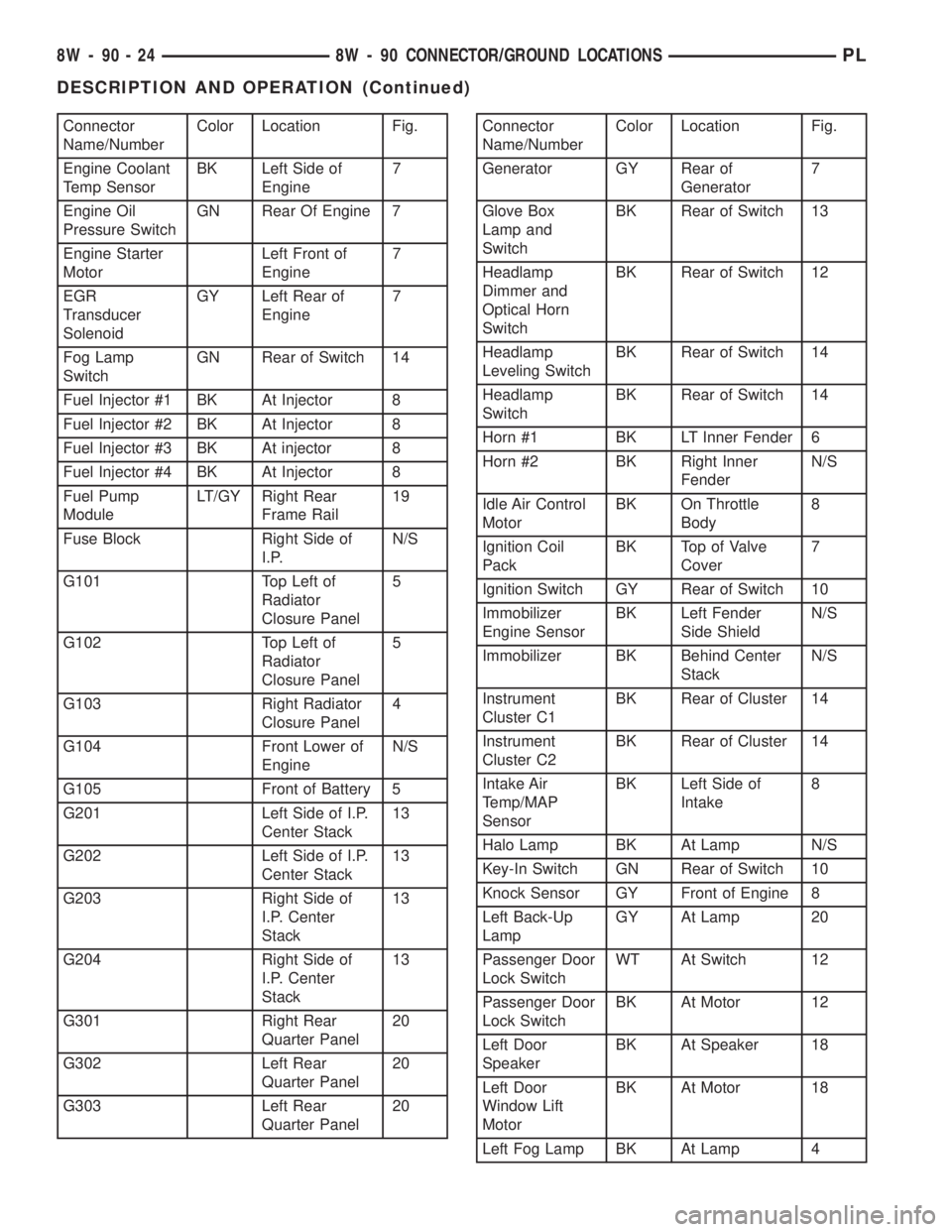
Connector
Name/NumberColor Location Fig.
Engine Coolant
Temp SensorBK Left Side of
Engine7
Engine Oil
Pressure SwitchGN Rear Of Engine 7
Engine Starter
MotorLeft Front of
Engine7
EGR
Transducer
SolenoidGY Left Rear of
Engine7
Fog Lamp
SwitchGN Rear of Switch 14
Fuel Injector #1 BK At Injector 8
Fuel Injector #2 BK At Injector 8
Fuel Injector #3 BK At injector 8
Fuel Injector #4 BK At Injector 8
Fuel Pump
ModuleLT/GY Right Rear
Frame Rail19
Fuse Block Right Side of
I.P.N/S
G101 Top Left of
Radiator
Closure Panel5
G102 Top Left of
Radiator
Closure Panel5
G103 Right Radiator
Closure Panel4
G104 Front Lower of
EngineN/S
G105 Front of Battery 5
G201 Left Side of I.P.
Center Stack13
G202 Left Side of I.P.
Center Stack13
G203 Right Side of
I.P. Center
Stack13
G204 Right Side of
I.P. Center
Stack13
G301 Right Rear
Quarter Panel20
G302 Left Rear
Quarter Panel20
G303 Left Rear
Quarter Panel20Connector
Name/NumberColor Location Fig.
Generator GY Rear of
Generator7
Glove Box
Lamp and
SwitchBK Rear of Switch 13
Headlamp
Dimmer and
Optical Horn
SwitchBK Rear of Switch 12
Headlamp
Leveling SwitchBK Rear of Switch 14
Headlamp
SwitchBK Rear of Switch 14
Horn #1 BK LT Inner Fender 6
Horn #2 BK Right Inner
FenderN/S
Idle Air Control
MotorBK On Throttle
Body8
Ignition Coil
PackBK Top of Valve
Cover7
Ignition Switch GY Rear of Switch 10
Immobilizer
Engine SensorBK Left Fender
Side ShieldN/S
Immobilizer BK Behind Center
StackN/S
Instrument
Cluster C1BK Rear of Cluster 14
Instrument
Cluster C2BK Rear of Cluster 14
Intake Air
Temp/MAP
SensorBK Left Side of
Intake8
Halo Lamp BK At Lamp N/S
Key-In Switch GN Rear of Switch 10
Knock Sensor GY Front of Engine 8
Left Back-Up
LampGY At Lamp 20
Passenger Door
Lock SwitchWT At Switch 12
Passenger Door
Lock SwitchBK At Motor 12
Left Door
SpeakerBK At Speaker 18
Left Door
Window Lift
MotorBK At Motor 18
Left Fog Lamp BK At Lamp 4
8W - 90 - 24 8W - 90 CONNECTOR/GROUND LOCATIONSPL
DESCRIPTION AND OPERATION (Continued)