warning light DODGE NEON 1999 Service Repair Manual
[x] Cancel search | Manufacturer: DODGE, Model Year: 1999, Model line: NEON, Model: DODGE NEON 1999Pages: 1200, PDF Size: 35.29 MB
Page 89 of 1200
either through the park brake switch, the fluid level
sensor in the master cylinder reservoir, or the igni-
tion switch in the crank position.
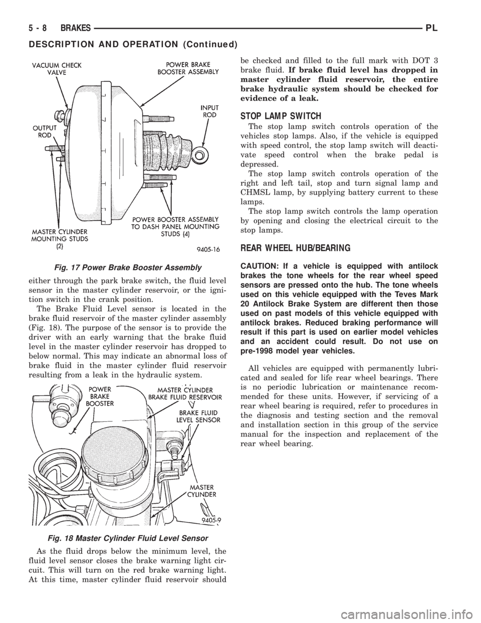
The Brake Fluid Level sensor is located in the
brake fluid reservoir of the master cylinder assembly
(Fig. 18). The purpose of the sensor is to provide the
driver with an early warning that the brake fluid
level in the master cylinder reservoir has dropped to
below normal. This may indicate an abnormal loss of
brake fluid in the master cylinder fluid reservoir
resulting from a leak in the hydraulic system.
As the fluid drops below the minimum level, the
fluid level sensor closes the brake warning light cir-
cuit. This will turn on the red brake warning light.
At this time, master cylinder fluid reservoir shouldbe checked and filled to the full mark with DOT 3
brake fluid.If brake fluid level has dropped in
master cylinder fluid reservoir, the entire
brake hydraulic system should be checked for
evidence of a leak.
STOP LAMP SWITCH
The stop lamp switch controls operation of the
vehicles stop lamps. Also, if the vehicle is equipped
with speed control, the stop lamp switch will deacti-
vate speed control when the brake pedal is
depressed.
The stop lamp switch controls operation of the
right and left tail, stop and turn signal lamp and
CHMSL lamp, by supplying battery current to these
lamps.
The stop lamp switch controls the lamp operation
by opening and closing the electrical circuit to the
stop lamps.
REAR WHEEL HUB/BEARING
CAUTION: If a vehicle is equipped with antilock
brakes the tone wheels for the rear wheel speed
sensors are pressed onto the hub. The tone wheels
used on this vehicle equipped with the Teves Mark
20 Antilock Brake System are different then those
used on past models of this vehicle equipped with
antilock brakes. Reduced braking performance will
result if this part is used on earlier model vehicles
and an accident could result. Do not use on
pre-1998 model year vehicles.
All vehicles are equipped with permanently lubri-
cated and sealed for life rear wheel bearings. There
is no periodic lubrication or maintenance recom-
mended for these units. However, if servicing of a
rear wheel bearing is required, refer to procedures in
the diagnosis and testing section and the removal
and installation section in this group of the service
manual for the inspection and replacement of the
rear wheel bearing.Fig. 17 Power Brake Booster Assembly
Fig. 18 Master Cylinder Fluid Level Sensor
5 - 8 BRAKESPL
DESCRIPTION AND OPERATION (Continued)
Page 90 of 1200
DIAGNOSIS AND TESTING
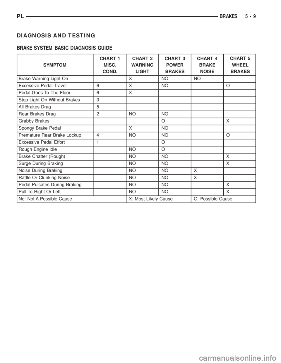
BRAKE SYSTEM BASIC DIAGNOSIS GUIDE
SYMPTOMCHART 1
MISC.
COND.CHART 2
WARNING
LIGHTCHART 3
POWER
BRAKESCHART 4
BRAKE
NOISECHART 5
WHEEL
BRAKES
Brake Warning Light On X NO NO
Excessive Pedal Travel 6 X NO O
Pedal Goes To The Floor 6 X
Stop Light On Without Brakes 3
All Brakes Drag 5
Rear Brakes Drag 2 NO NO
Grabby Brakes O X
Spongy Brake Pedal X NO
Premature Rear Brake Lockup 4 NO NO O
Excessive Pedal Effort 1 O
Rough Engine Idle NO O
Brake Chatter (Rough) NO NO X
Surge During Braking NO NO X
Noise During Braking NO NO X
Rattle Or Clunking Noise NO NO X
Pedal Pulsates During Braking NO NO X
Pull To Right Or Left NO NO X
No: Not A Possible Cause X: Most Likely Cause O: Possible Cause
PLBRAKES 5 - 9
Page 100 of 1200
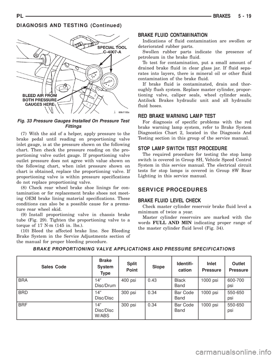
(7) With the aid of a helper, apply pressure to the
brake pedal until reading on proportioning valve
inlet gauge, is at the pressure shown on the following
chart. Then check the pressure reading on the pro-
portioning valve outlet gauge. If proportioning valve
outlet pressure does not agree with value shown on
the following chart, when inlet pressure shown on
chart is obtained, replace the proportioning valve. If
proportioning valve is within pressure specifications
do not replace proportioning valve.
(8) Check rear wheel brake shoe linings for con-
tamination or for replacement brake shoes not meet-
ing OEM brake lining material specifications. These
conditions can also be a possible cause for a prema-
ture rear wheel skid.
(9) Install proportioning valve in chassis brake
tube (Fig. 29). Tighten the proportioning valve to a
torque of 17 N´m (145 in. lbs.).
(10) Bleed the affected brake line. See Bleeding
Brake System in the Service Adjustments section of
the manual for proper bleeding procedure.
BRAKE FLUID CONTAMINATION
Indications of fluid contamination are swollen or
deteriorated rubber parts.
Swollen rubber parts indicate the presence of
petroleum in the brake fluid.
To test for contamination, put a small amount of
drained brake fluid in clear glass jar. If fluid sepa-
rates into layers, there is mineral oil or other fluid
contamination of the brake fluid.
If brake fluid is contaminated, drain and thor-
oughly flush system. Replace master cylinder, propor-
tioning valve, caliper seals, wheel cylinder seals,
Antilock Brakes hydraulic unit and all hydraulic
fluid hoses.
RED BRAKE WARNING LAMP TEST
For diagnosis of specific problems with the red
brake warning lamp system, refer to Brake System
Diagnostics Chart 2, located in the Diagnosis And
Testing section in this group of the service manual.
STOP LAMP SWITCH TEST PROCEDURE
The required procedure for testing the stop lamp
switch is covered in Group 8H, Vehicle Speed Control
System in this service manual. The electrical circuit
tests for stop lamps is covered in Group 8W Rear
Lighting in this service manual.
SERVICE PROCEDURES
BRAKE FLUID LEVEL CHECK
Check master cylinder reservoir brake fluid level a
minimum of twice a year.
Master cylinder reservoirs are marked with the
wordsFULL AND MINindicating proper range of
the master cylinder fluid level (Fig. 34).
Fig. 33 Pressure Gauges Installed On Pressure Test
Fittings
BRAKE PROPORTIONING VALVE APPLICATIONS AND PRESSURE SPECIFICATIONS
Sales CodeBrake
System
TypeSplit
PointSlopeIdentifi-
cationInlet
PressureOutlet
Pressure
BRA 149
Disc/Drum400 psi 0.43 Black
Band1000 psi 600-700
psi
BRD 149
Disc/Disc300 psi 0.34 Bar Code
Band1000 psi 550-650
psi
BRF 149
Disc/Disc
W/ABS300 psi 0.34 Bar Code
Band1000 psi 550-650
psi
PLBRAKES 5 - 19
DIAGNOSIS AND TESTING (Continued)
Page 130 of 1200
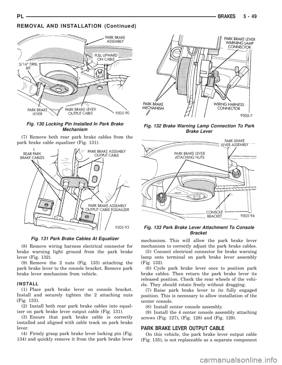
(7) Remove both rear park brake cables from the
park brake cable equalizer (Fig. 131).
(8) Remove wiring harness electrical connector for
brake warning light ground from the park brake
lever (Fig. 132).
(9) Remove the 2 nuts (Fig. 133) attaching the
park brake lever to the console bracket. Remove park
brake lever mechanism from vehicle.
INSTALL
(1) Place park brake lever on console bracket.
Install and securely tighten the 2 attaching nuts
(Fig. 133).
(2) Install both rear park brake cables into equal-
izer on park brake lever output cable (Fig. 131).
(3) Ensure that park brake cable is correctly
installed and aligned with cable track on park brake
lever.
(4) Firmly grasp park brake lever locking pin (Fig.
134) and quickly remove it from the park brake levermechanism. This will allow the park brake lever
mechanism to correctly adjust the park brake cables.
(5) Connect electrical connector for brake warning
lamp onto terminal on park brake lever assembly
(Fig. 132).
(6) Cycle park brake lever once to position park
brake cables. Then return the park brake lever its
released position. Check the rear wheels of the vehi-
cle. They should rotate freely without dragging.
(7) Raise park brake lever to its fully engaged
position. This is necessary to allow installation of the
center console.
(8) Install center console assembly.
(9) Install the 4 center console assembly attaching
screws (Fig. 127), (Fig. 128) and (Fig. 129).
PARK BRAKE LEVER OUTPUT CABLE
On this vehicle, the park brake lever output cable
(Fig. 135), is not replaceable as a separate component
Fig. 130 Locking Pin Installed In Park Brake
Mechanism
Fig. 131 Park Brake Cables At Equalizer
Fig. 132 Brake Warning Lamp Connection To Park
Brake Lever
Fig. 133 Park Brake Lever Attachment To Console
Bracket
PLBRAKES 5 - 49
REMOVAL AND INSTALLATION (Continued)
Page 151 of 1200
This is accomplished by a sophisticated system of
electrical and hydraulic components. As a result,
there are a few performance characteristics that may
at first seem different but should be considered nor-
mal. These characteristics are discussed below.
NORMAL BRAKING SYSTEM FUNCTION
Under normal braking conditions, the ABS System
functions the same as a standard brake system with
a diagonally split master cylinder and conventional
vacuum assist.
ABS SYSTEM OPERATION
If a wheel locking tendency is detected during a
brake application, the brake system will enter the
ABS mode. During ABS braking, hydraulic pressure
in the four wheel circuits is modulated to prevent
any wheel from locking. Each wheel circuit is
designed with a set of electric solenoids to allow mod-
ulation, although for vehicle stability, both rear
wheel solenoids receive the same electrical signal.
During an ABS stop, the brakes hydraulic system
is still diagonally split. However, the brake system
pressure is further split into four control channels.
During antilock operation of the vehicle's brake sys-
tem the front wheels are controlled independently
and are on two separate control channels and the
rear wheels of the vehicle are controlled together.
The system can build and release pressure at each
wheel, depending on signals generated by the wheel
speed sensors (WSS) at each wheel and received at
the Controller Antilock Brake (CAB).
ABS operation is available at all vehicle speeds
above 3 to 5 mph. Wheel lockup may be perceived at
the very end of an ABS stop and is considered nor-
mal.
VEHICLE HANDLING PERFORMANCE DURING
ABS BRAKING
It is important to remember that an antilock brake
system does not shorten a vehicle's stopping distance
under all driving conditions, but does provide
improved control of the vehicle while stopping. Vehi-
cle stopping distance is still dependent on vehicle
speed, weight, tires, road surfaces and other factors.
Though ABS provides the driver with some steer-
ing control during hard braking, there are conditions
however, where the system does not provide any ben-
efit. In particular, hydroplaning is still possible when
the tires ride on a film of water. This results in the
vehicles tires leaving the road surface rendering the
vehicle virtually uncontrollable. In addition, extreme
steering maneuvers at high speed or high speed cor-
nering beyond the limits of tire adhesion to the road
surface may cause vehicle skidding, independent of
vehicle braking. For this reason, the ABS system is
termed Antilock instead of Anti-Skid.
NOISE AND BRAKE PEDAL FEEL
During ABS braking, some brake pedal movement
may be felt. In addition, ABS braking will create
ticking, popping and/or groaning noises heard by the
driver. This is normal due to pressurized fluid being
transferred between the master cylinder and the
brakes. If ABS operation occurs during hard braking,
some pulsation may be felt in the vehicle body due to
fore and aft movement of the suspension as brake
pressures are modulated.
At the end of an ABS stop, ABS will be turned off
when the vehicle is slowed to a speed of 3±4 mph.
There may be a slight brake pedal drop anytime that
the ABS is deactivated, such as at the end of the stop
when the vehicle speed is less then 3 mph or during
an ABS stop where ABS is no longer required. These
conditions will exist when a vehicle is being stopped
on a road surface with patches of ice, loose gravel or
sand on it. Also stopping a vehicle on a bumpy road
surface will activate ABS because of the wheel hop
caused by the bumps.
TIRE NOISE AND MARKS
Although the ABS system prevents complete wheel
lock-up, some wheel slip is desired in order to
achieve optimum braking performance. Wheel slip is
defined as follows, 0 percent slip means the wheel is
rolling freely and 100 percent slip means the wheel is
fully locked. During brake pressure modulation,
wheel slip is allowed to reach up to 25 to30%. This
means that the wheel rolling velocity is 25 to 30%
less than that of a free rolling wheel at a given vehi-
cle speed. This slip may result in some tire chirping,
depending on the road surface. This sound should not
be interpreted as total wheel lock-up.
Complete wheel lock up normally leaves black tire
marks on dry pavement. The ABS System will not
leave dark black tire marks since the wheel never
reaches a fully locked condition. Tire marks may
however be noticeable as light patched marks.
START UP CYCLE
When the ignition is turned on, a popping sound
and a slight brake pedal movement may be noticed.
Additionally, when the vehicle is first driven off a
humming may be heard and/or felt by the driver at
approximately 20 to 40 kph (12 to 25 mph). The ABS
warning lamp will also be on for up to 5 seconds
after the ignition is turned on. All of these conditions
are a normal function of ABS as the system is per-
forming a diagnosis check.
5 - 70 BRAKESPL
DESCRIPTION AND OPERATION (Continued)
Page 156 of 1200
cally cleared from the CAB memory after the identi-
cal fault has not been seen during the next 255 key
cycles of vehicle operation.
CONTROLLER ANTILOCK BRAKE INPUTS
²Four wheel speed sensors.
²Stop lamp switch.
²Ignition switch.
²System relay voltage.
²Ground.
²Diagnostics Communications (CCD)
CONTROLLER ANTILOCK BRAKE OUTPUTS
²ABS warning lamp actuation.
²Diagnostic communication. (CCD)
ABS WARNING LAMP (YELLOW)
The ABS system uses a yellow colored ABS Warn-
ing Lamp. The ABS warning lamp is located on the
lower left side of the instrument pane. The purpose
of the warning lamp is discussed in detail below.
The ABS warning lamp will turn on when the CAB
detects a condition which results in a shutdown of
ABS function. When the ignition key is turned to the
on position, the ABS Warning Lamp is on until the
CAB completes its self tests and turns the lamp off
(approximately 4 seconds after the ignition switch is
turned on). Under most conditions, when the ABS
warning lamp is on, only the ABS function of the
brake system is affected. The standard brake system
and the ability to stop the car will not be affected
when only the ABS warning lamp is on.
The ABS warning lamp is controlled by the CAB.
The CAB turns on the yellow ABS warning lamp by
grounding the circuit.
HYDRAULIC CIRCUITS AND VALVE OPERATION
Through the following operation descriptions the
function of the various hydraulic control valves in the
ABS will be described. The fluid control valves men-
tioned below, control the flow of pressurized brake
fluid to the wheel brakes during the different modes
of ABS braking.
For explanation purposes, all wheel speed sensors
except the right front are sending the same wheel
speed information. The following diagrams show only
the right front wheel in a antilock braking condition.
NORMAL BRAKING HYDRAULIC CIRCUIT AND
SOLENOID VALVE FUNCTION
This condition is the normal operation of the vehi-
cles base brake hydraulic system. The hydraulic sys-
tem circuit diagram (Fig. 11) shows a situation where
no wheel spin or slip is occurring relative to the
speed of the vehicle. The driver is applying the brake
pedal to build pressure in the brake hydraulic system
to apply the brakes and stop the vehicle.
TEVES MARK 20 ABS CIRCUIT AND
SOLENOID VALVE FUNCTION
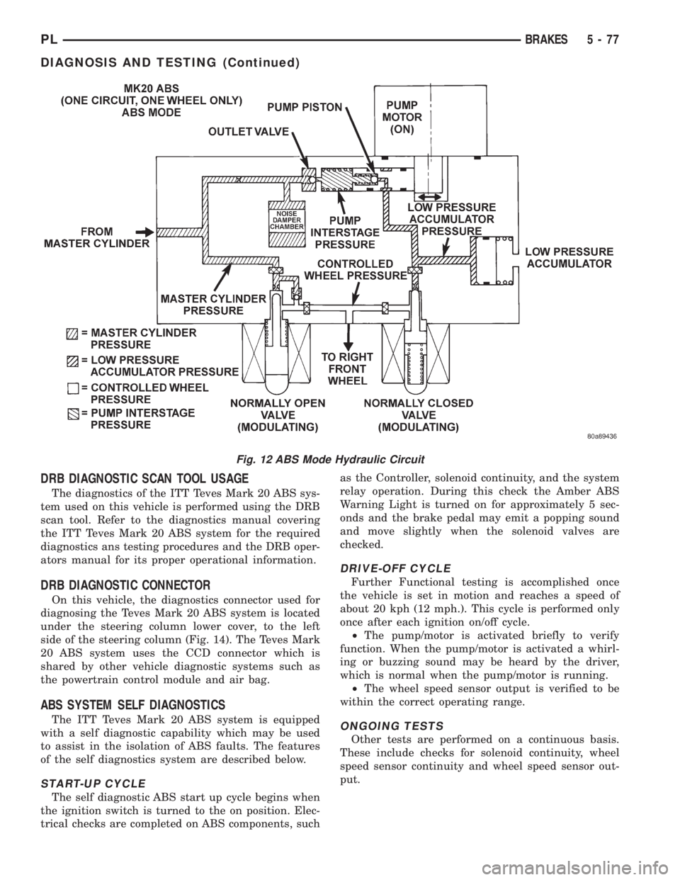
This hydraulic circuit diagram (Fig. 12) shows the
vehicle in the ABS braking mode. This hydraulic cir-
cuit (Fig. 12) shows a situation where one wheel is
slipping because the driver is attempting to stop the
vehicle at a faster rate than the surface the vehicle's
tires are on will allow. The normally open and nor-
mally closed valves modulate the brake hydraulic
pressure as required. The pump/motor is switched on
so that the brake fluid from the low pressure accu-
mulators is returned to the master cylinder circuits.
The brake fluid will then be routed to either the mas-
ter cylinder or the wheel brake depending on the
position of the normally open valve.
TEVES MARK 20 SECONDARY ABS CIRCUIT
AND SOLENOID VALVE FUNCTION
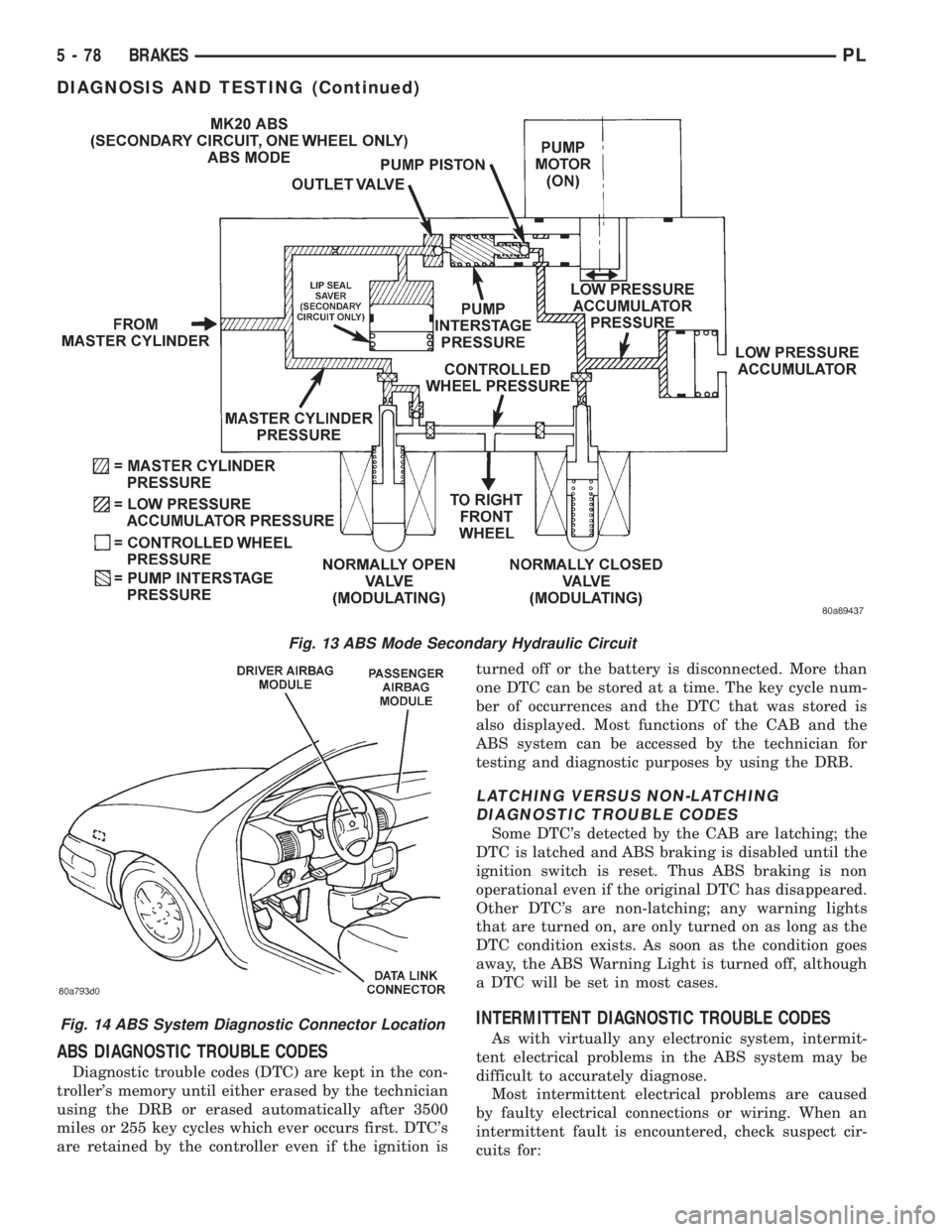
This hydraulic circuit diagram (Fig. 13) shows the
vehicle in the ABS braking mode. This hydraulic cir-
cuit (Fig. 13) shows a situation where one wheel is
slipping because the driver is attempting to stop the
vehicle at a faster rate than the surface the vehicle's
tires are on will allow. The normally open and nor-
mally closed valves modulate the brake hydraulic
pressure as required. The pump/motor is switched on
so that the brake fluid from the low pressure accu-
mulators is returned to the master cylinder circuits.
The brake fluid will then be routed to either the mas-
ter cylinder or the wheel brake depending on the
position of the normally open valve. A volume of 1.2
cc's of brake fluid is taken in by the lip seal saver
(Fig. 13) to protect the lip seals on the piston of the
master cylinder.
DIAGNOSIS AND TESTING
ABS GENERAL DIAGNOSTICS INFORMATION
This section contains the information necessary to
diagnose the ITT Teves Mark 20 ABS Brake System.
Specifically, this section should be used to help diag-
nose conditions which result in any of the following:
(1) ABS Warning Lamp turned on.
(2) Brakes Lock-up on hard application
Diagnosis of base brake conditions which are obvi-
ously mechanical in nature should be directed to
Group 5 Brakes in this service manual. This includes
brake noise, brake pulsation, lack of power assist,
parking brake, Red BRAKE Warning Lamp lighting,
or vehicle vibration during normal braking.
Many conditions that generate customer com-
plaints may be normal operating conditions, but are
judged to be a problem due to not being familiar with
the ABS system. These conditions can be recognized
without performing extensive diagnostic work, given
adequate understanding of the operating principles
PLBRAKES 5 - 75
DESCRIPTION AND OPERATION (Continued)
Page 158 of 1200
DRB DIAGNOSTIC SCAN TOOL USAGE
The diagnostics of the ITT Teves Mark 20 ABS sys-
tem used on this vehicle is performed using the DRB
scan tool. Refer to the diagnostics manual covering
the ITT Teves Mark 20 ABS system for the required
diagnostics ans testing procedures and the DRB oper-
ators manual for its proper operational information.
DRB DIAGNOSTIC CONNECTOR
On this vehicle, the diagnostics connector used for
diagnosing the Teves Mark 20 ABS system is located
under the steering column lower cover, to the left
side of the steering column (Fig. 14). The Teves Mark
20 ABS system uses the CCD connector which is
shared by other vehicle diagnostic systems such as
the powertrain control module and air bag.
ABS SYSTEM SELF DIAGNOSTICS
The ITT Teves Mark 20 ABS system is equipped
with a self diagnostic capability which may be used
to assist in the isolation of ABS faults. The features
of the self diagnostics system are described below.
START-UP CYCLE
The self diagnostic ABS start up cycle begins when
the ignition switch is turned to the on position. Elec-
trical checks are completed on ABS components, suchas the Controller, solenoid continuity, and the system
relay operation. During this check the Amber ABS
Warning Light is turned on for approximately 5 sec-
onds and the brake pedal may emit a popping sound
and move slightly when the solenoid valves are
checked.
DRIVE-OFF CYCLE
Further Functional testing is accomplished once
the vehicle is set in motion and reaches a speed of
about 20 kph (12 mph.). This cycle is performed only
once after each ignition on/off cycle.
²The pump/motor is activated briefly to verify
function. When the pump/motor is activated a whirl-
ing or buzzing sound may be heard by the driver,
which is normal when the pump/motor is running.
²The wheel speed sensor output is verified to be
within the correct operating range.
ONGOING TESTS
Other tests are performed on a continuous basis.
These include checks for solenoid continuity, wheel
speed sensor continuity and wheel speed sensor out-
put.
Fig. 12 ABS Mode Hydraulic Circuit
PLBRAKES 5 - 77
DIAGNOSIS AND TESTING (Continued)
Page 159 of 1200
ABS DIAGNOSTIC TROUBLE CODES
Diagnostic trouble codes (DTC) are kept in the con-
troller's memory until either erased by the technician
using the DRB or erased automatically after 3500
miles or 255 key cycles which ever occurs first. DTC's
are retained by the controller even if the ignition isturned off or the battery is disconnected. More than
one DTC can be stored at a time. The key cycle num-
ber of occurrences and the DTC that was stored is
also displayed. Most functions of the CAB and the
ABS system can be accessed by the technician for
testing and diagnostic purposes by using the DRB.
LATCHING VERSUS NON-LATCHING
DIAGNOSTIC TROUBLE CODES
Some DTC's detected by the CAB are latching; the
DTC is latched and ABS braking is disabled until the
ignition switch is reset. Thus ABS braking is non
operational even if the original DTC has disappeared.
Other DTC's are non-latching; any warning lights
that are turned on, are only turned on as long as the
DTC condition exists. As soon as the condition goes
away, the ABS Warning Light is turned off, although
a DTC will be set in most cases.
INTERMITTENT DIAGNOSTIC TROUBLE CODES
As with virtually any electronic system, intermit-
tent electrical problems in the ABS system may be
difficult to accurately diagnose.
Most intermittent electrical problems are caused
by faulty electrical connections or wiring. When an
intermittent fault is encountered, check suspect cir-
cuits for:
Fig. 13 ABS Mode Secondary Hydraulic Circuit
Fig. 14 ABS System Diagnostic Connector Location
5 - 78 BRAKESPL
DIAGNOSIS AND TESTING (Continued)
Page 174 of 1200
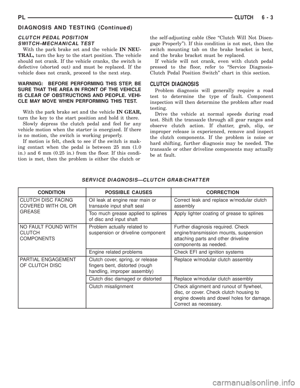
CLUTCH PEDAL POSITION
SWITCH±MECHANICAL TEST
With the park brake set and the vehicleIN NEU-
TRAL,turn the key to the start position. The vehicle
should not crank. If the vehicle cranks, the switch is
defective (shorted out) and must be replaced. If the
vehicle does not crank, proceed to the next step.
WARNING: BEFORE PERFORMING THIS STEP, BE
SURE THAT THE AREA IN FRONT OF THE VEHICLE
IS CLEAR OF OBSTRUCTIONS AND PEOPLE. VEHI-
CLE MAY MOVE WHEN PERFORMING THIS TEST.
With the park brake set and the vehicleIN GEAR,
turn the key to the start position and hold it there.
Slowly depress the clutch pedal and feel for any
vehicle motion when the starter is energized. If there
is no motion, the switch is working properly.
If motion is felt, check to see if the switch is mak-
ing contact when the pedal is between 25 mm (1.0
in.) and 6 mm (0.25 in.) from the floor. If this condi-
tion is met, then the problem is either the clutch orthe self-adjusting cable (See ªClutch Will Not Disen-
gage Properlyº). If this condition is not met, then the
switch mounting tab on the brake bracket is bent,
and the brake bracket must be replaced.
If vehicle will not crank, even with clutch pedal
pressed to the floor, refer to ªService Diagnosis-
Clutch Pedal Position Switchº chart in this section.
CLUTCH DIAGNOSIS
Problem diagnosis will generally require a road
test to determine the type of fault. Component
inspection will then determine the problem after road
testing.
Drive the vehicle at normal speeds during road
test. Shift the transaxle through all gear ranges and
observe clutch action. If chatter, grab, slip, or
improper release is experienced, remove and inspect
the clutch components. If the problem is noise or
hard shifting, further diagnosis may be needed. The
transaxle or other driveline components may actually
be at fault.
SERVICE DIAGNOSISÐCLUTCH GRAB/CHATTER
CONDITION POSSIBLE CAUSES CORRECTION
CLUTCH DISC FACING
COVERED WITH OIL OR
GREASEOil leak at engine rear main or
transaxle input shaft sealCorrect leak and replace w/modular clutch
assembly
Too much grease applied to splines
of disc and input shaftApply lighter coating of grease to splines
NO FAULT FOUND WITH
CLUTCH
COMPONENTSProblem actually related to
suspension or driveline componentFurther diagnosis required. Check
engine/transmission mounts, suspension
attaching parts and other driveline
components as needed.
Engine related problems Check EFI and ignition systems
PARTIAL ENGAGEMENT
OF CLUTCH DISCClutch cover, spring, or release
fingers bent, distorted (rough
handling, improper assembly)Replace w/modular clutch assembly
Clutch disc damaged or distorted Replace w/modular clutch assembly
Clutch misalignment Check alignment and runout of flywheel,
disc, or cover. Check clutch housing to
engine dowels and dowel holes for damage.
Correct as necessary.
PLCLUTCH 6 - 3
DIAGNOSIS AND TESTING (Continued)
Page 198 of 1200
SELECTION AND ADDITIVES
The use of aluminum cylinder heads, intake mani-
folds DOHC, and water pumps requires special corro-
sion protection. MopartAntifreeze or the equivalent
is recommended for best engine cooling without cor-
rosion. When mixed only to a freeze point of -37ÉC
(-35ÉF) to -59ÉC (-50ÉF). If it looses color or becomes
contaminated, drain, flush, and replace with fresh
properly mixed solution.
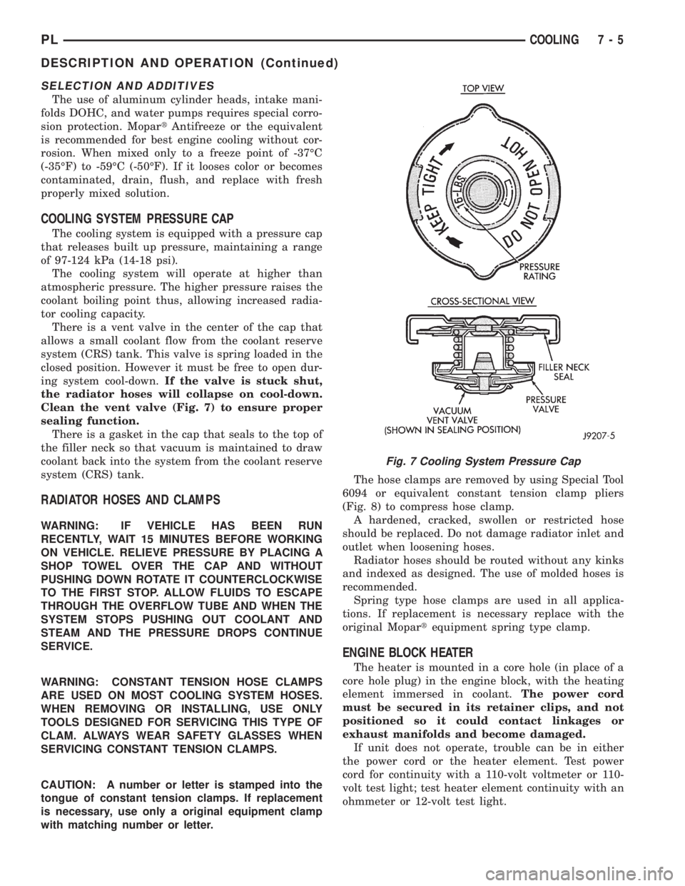
COOLING SYSTEM PRESSURE CAP
The cooling system is equipped with a pressure cap
that releases built up pressure, maintaining a range
of 97-124 kPa (14-18 psi).
The cooling system will operate at higher than
atmospheric pressure. The higher pressure raises the
coolant boiling point thus, allowing increased radia-
tor cooling capacity.
There is a vent valve in the center of the cap that
allows a small coolant flow from the coolant reserve
system (CRS) tank. This valve is spring loaded in the
closed position. However it must be free to open dur-
ing system cool-down.If the valve is stuck shut,
the radiator hoses will collapse on cool-down.
Clean the vent valve (Fig. 7) to ensure proper
sealing function.
There is a gasket in the cap that seals to the top of
the filler neck so that vacuum is maintained to draw
coolant back into the system from the coolant reserve
system (CRS) tank.
RADIATOR HOSES AND CLAMPS
WARNING: IF VEHICLE HAS BEEN RUN
RECENTLY, WAIT 15 MINUTES BEFORE WORKING
ON VEHICLE. RELIEVE PRESSURE BY PLACING A
SHOP TOWEL OVER THE CAP AND WITHOUT
PUSHING DOWN ROTATE IT COUNTERCLOCKWISE
TO THE FIRST STOP. ALLOW FLUIDS TO ESCAPE
THROUGH THE OVERFLOW TUBE AND WHEN THE
SYSTEM STOPS PUSHING OUT COOLANT AND
STEAM AND THE PRESSURE DROPS CONTINUE
SERVICE.
WARNING: CONSTANT TENSION HOSE CLAMPS
ARE USED ON MOST COOLING SYSTEM HOSES.
WHEN REMOVING OR INSTALLING, USE ONLY
TOOLS DESIGNED FOR SERVICING THIS TYPE OF
CLAM. ALWAYS WEAR SAFETY GLASSES WHEN
SERVICING CONSTANT TENSION CLAMPS.
CAUTION: A number or letter is stamped into the
tongue of constant tension clamps. If replacement
is necessary, use only a original equipment clamp
with matching number or letter.The hose clamps are removed by using Special Tool
6094 or equivalent constant tension clamp pliers
(Fig. 8) to compress hose clamp.
A hardened, cracked, swollen or restricted hose
should be replaced. Do not damage radiator inlet and
outlet when loosening hoses.
Radiator hoses should be routed without any kinks
and indexed as designed. The use of molded hoses is
recommended.
Spring type hose clamps are used in all applica-
tions. If replacement is necessary replace with the
original Mopartequipment spring type clamp.
ENGINE BLOCK HEATER
The heater is mounted in a core hole (in place of a
core hole plug) in the engine block, with the heating
element immersed in coolant.The power cord
must be secured in its retainer clips, and not
positioned so it could contact linkages or
exhaust manifolds and become damaged.
If unit does not operate, trouble can be in either
the power cord or the heater element. Test power
cord for continuity with a 110-volt voltmeter or 110-
volt test light; test heater element continuity with an
ohmmeter or 12-volt test light.
Fig. 7 Cooling System Pressure Cap
PLCOOLING 7 - 5
DESCRIPTION AND OPERATION (Continued)