audio DODGE NEON 1999 Service Repair Manual
[x] Cancel search | Manufacturer: DODGE, Model Year: 1999, Model line: NEON, Model: DODGE NEON 1999Pages: 1200, PDF Size: 35.29 MB
Page 281 of 1200
(6) Remove the screws attaching lens, dial and
gauge assembly to the housing. The bottom screws
attaching lens to the housing can be accessed without
removing the foam pad.
(7) Remove the lens, dial and gauge assembly from
housing.
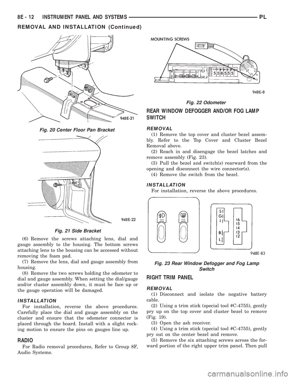
(8) Remove the two screws holding the odometer to
dial and gauge assembly. When setting the dial/gauge
and/or cluster assembly down, it must be face up or
the gauge operation will be damaged.
INSTALLATION
For installation, reverse the above procedures.
Carefully place the dial and gauge assembly on the
cluster and ensure that the odometer connector is
placed through the board. Install with a slight rock-
ing motion to ensure the pins on gauges line up.
RADIO
For Radio removal procedures, Refer to Group 8F,
Audio Systems.
REAR WINDOW DEFOGGER AND/OR FOG LAMP
SWITCH
REMOVAL
(1) Remove the top cover and cluster bezel assem-
bly. Refer to the Top Cover and Cluster Bezel
Removal above.
(2) Reach in and disengage the bezel latches and
remove assembly (Fig. 23).
(3) Pull the bezel and switch(s) rearward from the
opening and disconnect the wire connector(s).
(4) Remove the switch from the bezel.
INSTALLATION
For installation, reverse the above procedures.
RIGHT TRIM PANEL
REMOVAL
(1) Disconnect and isolate the negative battery
cable.
(2) Using a trim stick (special tool #C-4755), gently
pry up on the top cover and cluster bezel to remove
(Fig. 19).
(3) Open the ash receiver.
(4) Using a trim stick (special tool #C-4755), gently
pry out on the center bezel and remove.
(5) Remove the six attaching screws across the for-
ward portion of the right upper trim panel. Then pull
Fig. 20 Center Floor Pan Bracket
Fig. 21 Side Bracket
Fig. 22 Odometer
Fig. 23 Rear Window Defogger and Fog Lamp
Switch
8E - 12 INSTRUMENT PANEL AND SYSTEMSPL
REMOVAL AND INSTALLATION (Continued)
Page 288 of 1200
AUDIO SYSTEM
CONTENTS
page page
GENERAL INFORMATION
INTRODUCTION......................... 1
DESCRIPTION AND OPERATION
INTERFERENCE ELIMINATION.............. 1
DIAGNOSIS AND TESTING
ANTENNA.............................. 3
AUDIO DIAGNOSTIC TEST PROCEDURES..... 1BENCH TEST FOR ANTENNA MALFUNCTION . . 3
REMOVAL AND INSTALLATION
ANTENNA.............................. 3
FRONT DOOR SPEAKER................... 4
INSTRUMENT PANEL SPEAKER............. 4
RADIO................................. 4
REAR SHELF SPEAKER(S)................. 5
GENERAL INFORMATION
INTRODUCTION
Operating instructions for the factory installed
audio systems can be found in the Owner's Manual
provided with the vehicle.
The vehicles are equipped with an Interior (Igni-
tion Off Draw) fuse in the Power Distribution Center
located in the engine compartment. After the Interior
(IOD) fuse or battery has been disconnected the clock
will require resetting.
DESCRIPTION AND OPERATION
INTERFERENCE ELIMINATION
The radio utilizes a ground wire plugged on to a
blade terminal and is bolted to the radio chassis.
Both connector and terminal should be securely
attached. The engine has three separate ground
straps to suppress ignition noise which may interfere
with radio reception.
²Left engine mount clip on strap
²Engine to shock tower reinforcement
²Rear strut to body, clip-on strap
Inductive type spark plug cables in the high ten-
sion circuit of the ignition system complete the inter-
ference suppression. Faulty or deteriorated spark
plug wires should be replaced.
In addition, there is a capacitor mounted on the
cylinder head which also helps suppress ignition
noise.
DIAGNOSIS AND TESTING
AUDIO DIAGNOSTIC TEST PROCEDURES
CAUTION: The CD player will only operate between
approximate temperatures of -23ÉC and +65ÉC (-10ÉF
and +145ÉF).
Whenever a radio malfunction occurs;
(1) First check FUSES:
(a) Power Distribution Center (PDC), Interior
lamp fuse, M1 - Radio Memory Feed
(b) Fuse Block:
(I) Fuse 12, Illumination in the fuse block
(II) Fuse 16, Ignition feed in the fuse block
NOTE: The vehicles are shipped with the INTERIOR
LAMP fuse disconnected.
(2) Verify, the radio wire harness are properly con-
nected before starting normal diagnosis and repair
procedures. Refer to Audio Diagnosis table and/or
Group 8W, Wiring Diagrams, Radio Section.
PLAUDIO SYSTEM 8F - 1
Page 289 of 1200
AUDIO SYSTEM DIAGNOSIS
CONDITION POSSIBLE CAUSE CORRECTION
NO AUDIO. 1. FUSE FAULTY.
2. RADIO CONNECTOR
FAULTY.
3. WIRING FAULTY.
4. GROUND FAULTY.
5. RADIO FAULTY.
6. SPEAKERS FAULTY.1. CHECK RADIO FUSES IN FUSEBLOCK MODULE. REPLACE
FUSES, IF REQUIRED.
2. CHECK FOR LOOSE OR CORRODED RADIO CONNECTOR.
REPAIR, IF REQUIRED.
3. CHECK FOR BATTERY VOLTAGE AT RADIO CONNECTOR.
REPAIR WIRING, IF REQUIRED.
4. CHECK FOR CONTINUITY BETWEEN RADIO CHASSIS AND
A KNOWN GOOD GROUND. THERE SHOULD BE
CONTINUITY. REPAIR GROUND, IF REQUIRED.
5. EXCHANGE OR REPLACE RADIO, IF REQUIRED.
6. SEE SPEAKER DIAGNOSIS, IN THIS GROUP.
NO DISPLAY. 1. FUSE FAULTY.
2. RADIO CONNECTOR
FAULTY.
3. WIRING FAULTY.
4. GROUND FAULTY.
5. RADIO FAULTY.1. CHECK RADIO FUSES IN FUSEBLOCK MODULE. REPLACE
FUSES, IF REQUIRED.
2. CHECK FOR LOOSE OR CORRODED RADIO CONNECTOR.
REPAIR, IF REQUIRED.
3. CHECK FOR BATTERY VOLTAGE AT RADIO CONNECTOR.
REPAIR WIRING, IF REQUIRED.
4. CHECK FOR CONTINUITY BETWEEN RADIO CHASSIS AND
A KNOWN GOOD GROUND. THERE SHOULD BE
CONTINUITY. REPAIR GROUND, IF REQUIRED.
5. EXCHANGE OR REPLACE RADIO, IF REQUIRED.
NO MEMORY. 1. FUSE FAULTY.
2. RADIO CONNECTOR
FAULTY.
3. WIRING FAULTY.
4. GROUND FAULTY.
5. RADIO FAULTY.1. CHECK IGNITION-OFF DRAW FUSE. REPLACE FUSE, IF
REQUIRED.
2. CHECK FOR LOOSE OR CORRODED RADIO CONNECTOR.
REPAIR, IF REQUIRED.
3. CHECK FOR BATTERY VOLTAGE AT RADIO CONNECTOR.
REPAIR WIRING, IF REQUIRED.
4. CHECK FOR CONTINUITY BETWEEN RADIO CHASSIS AND
A KNOWN GOOD GROUND. THERE SHOULD BE
CONTINUITY. REPAIR GROUND, IF REQUIRED.
5. EXCHANGE OR REPLACE RADIO, IF REQUIRED.
POOR RADIO
RECEPTION.1. ANTENNA FAULTY.
2. GROUND FAULTY.
3. RADIO FAULTY.1. SEE ANTENNA DIAGNOSIS, IN THIS GROUP. REPAIR OR
REPLACE ANTENNA, IF REQUIRED.
2. CHECK FOR CONTINUITY BETWEEN RADIO CHASSIS AND
A KNOWN GOOD GROUND. THERE SHOULD BE
CONTINUITY. REPAIR GROUND, IF REQUIRED..
3. EXCHANGE OR REPLACE RADIO, IF REQUIRED.
NO/POOR TAPE
OPERATION.1. FAULTY TAPE.
2. FOREIGN OBJECTS
BEHIND TAPE DOOR.
3. DIRTY CASSETTE
TAPE HEAD.
4. FAULTY TAPE DECK.1. INSERT KNOWN GOOD TAPE AND TEST OPERATION.
2. REMOVE FOREIGN OBJECTS AND TEST OPERATION.
3. CLEAN HEAD WITH MOPAR CASSETTE HEAD CLEANER.
4. EXCHANGE OR REPLACE RADIO, IF REQUIRED.
NO COMPACT
DISC
OPERATION1. FAULTY CD.
2. FOREIGN MATERIAL
ON CD.
3. CONDENSATION ON
CD OR OPTICS.
4. FAULTY CD PLAYER.1. INSERT KNOWN GOOD CD AND TEST OPERATION.
2. CLEAN CD AND TEST OPERATION.
3. ALLOW TEMPERATURE OF VEHICLE INTERIOR TO
STABILIZE AND TEST OPERATION.
4. EXCHANGE OR REPLACE RADIO, IF REQUIRED.
8F - 2 AUDIO SYSTEMPL
DIAGNOSIS AND TESTING (Continued)
Page 290 of 1200
ANTENNA
The antenna has a short cable which connects into
the instrument panel harness. The connection is
made on the right side of the instrument panel.
Antenna performance may be tested by substitut-
ing a known good antenna. It is also possible to
check short or open circuits with an ohmmeter or
continuity light once the antenna cable is discon-
nected from the radio as follows:
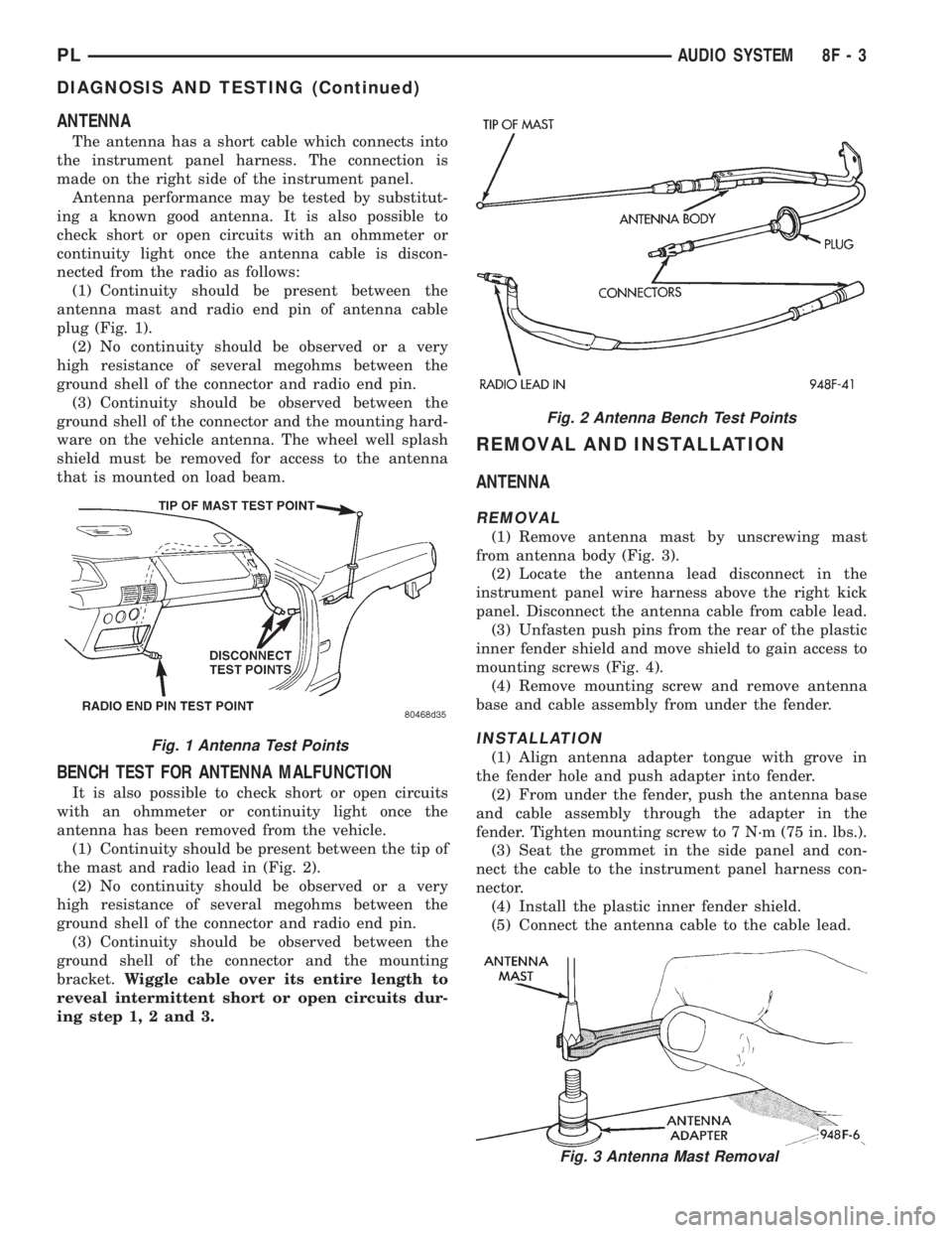
(1) Continuity should be present between the
antenna mast and radio end pin of antenna cable
plug (Fig. 1).
(2) No continuity should be observed or a very
high resistance of several megohms between the
ground shell of the connector and radio end pin.
(3) Continuity should be observed between the
ground shell of the connector and the mounting hard-
ware on the vehicle antenna. The wheel well splash
shield must be removed for access to the antenna
that is mounted on load beam.
BENCH TEST FOR ANTENNA MALFUNCTION
It is also possible to check short or open circuits
with an ohmmeter or continuity light once the
antenna has been removed from the vehicle.
(1) Continuity should be present between the tip of
the mast and radio lead in (Fig. 2).
(2) No continuity should be observed or a very
high resistance of several megohms between the
ground shell of the connector and radio end pin.
(3) Continuity should be observed between the
ground shell of the connector and the mounting
bracket.Wiggle cable over its entire length to
reveal intermittent short or open circuits dur-
ing step 1, 2 and 3.
REMOVAL AND INSTALLATION
ANTENNA
REMOVAL
(1) Remove antenna mast by unscrewing mast
from antenna body (Fig. 3).
(2) Locate the antenna lead disconnect in the
instrument panel wire harness above the right kick
panel. Disconnect the antenna cable from cable lead.
(3) Unfasten push pins from the rear of the plastic
inner fender shield and move shield to gain access to
mounting screws (Fig. 4).
(4) Remove mounting screw and remove antenna
base and cable assembly from under the fender.
INSTALLATION
(1) Align antenna adapter tongue with grove in
the fender hole and push adapter into fender.
(2) From under the fender, push the antenna base
and cable assembly through the adapter in the
fender. Tighten mounting screw to 7 N´m (75 in. lbs.).
(3) Seat the grommet in the side panel and con-
nect the cable to the instrument panel harness con-
nector.
(4) Install the plastic inner fender shield.
(5) Connect the antenna cable to the cable lead.
Fig. 2 Antenna Bench Test Points
Fig. 3 Antenna Mast Removal
Fig. 1 Antenna Test Points
PLAUDIO SYSTEM 8F - 3
DIAGNOSIS AND TESTING (Continued)
Page 291 of 1200
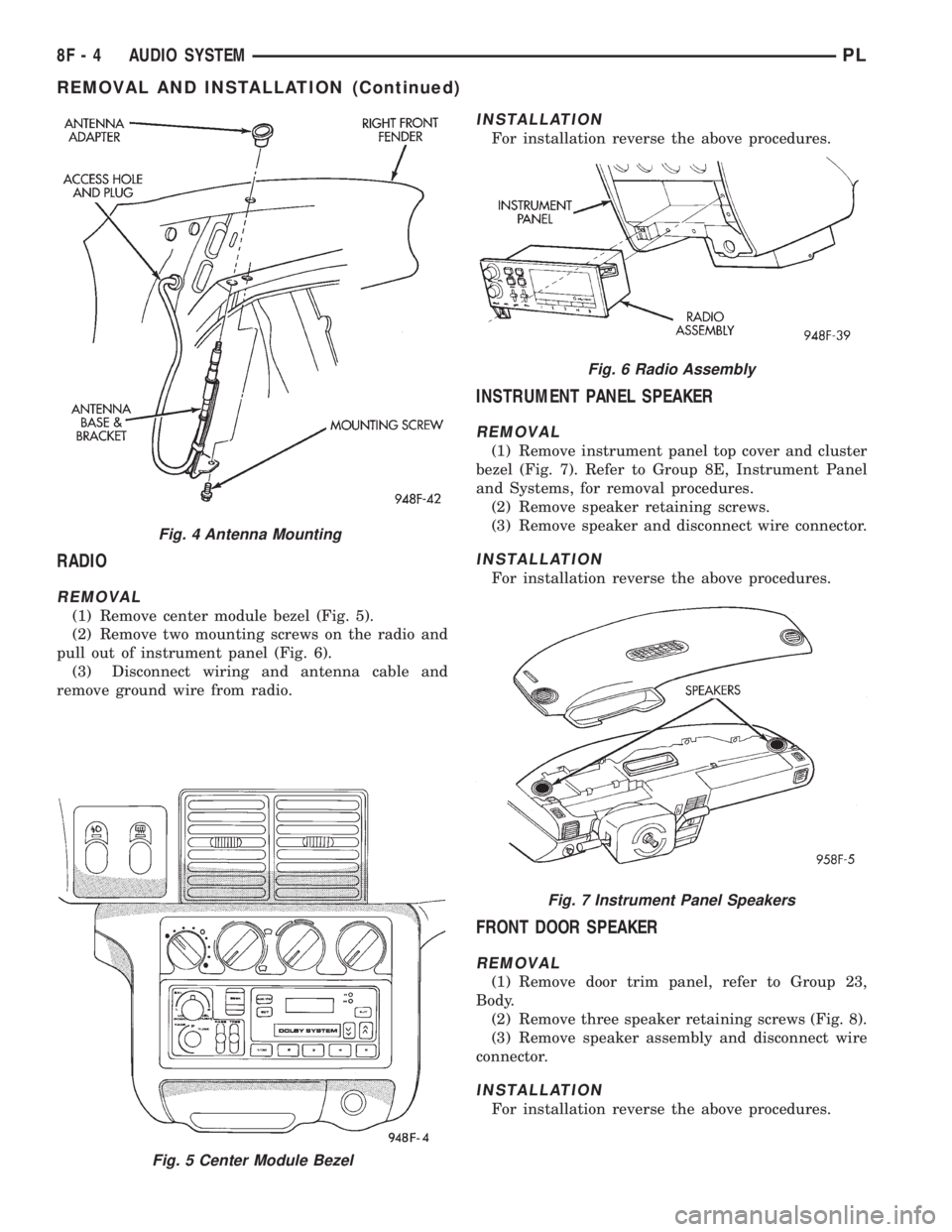
RADIO
REMOVAL
(1) Remove center module bezel (Fig. 5).
(2) Remove two mounting screws on the radio and
pull out of instrument panel (Fig. 6).
(3) Disconnect wiring and antenna cable and
remove ground wire from radio.
INSTALLATION
For installation reverse the above procedures.
INSTRUMENT PANEL SPEAKER
REMOVAL
(1) Remove instrument panel top cover and cluster
bezel (Fig. 7). Refer to Group 8E, Instrument Panel
and Systems, for removal procedures.
(2) Remove speaker retaining screws.
(3) Remove speaker and disconnect wire connector.
INSTALLATION
For installation reverse the above procedures.
FRONT DOOR SPEAKER
REMOVAL
(1) Remove door trim panel, refer to Group 23,
Body.
(2) Remove three speaker retaining screws (Fig. 8).
(3) Remove speaker assembly and disconnect wire
connector.
INSTALLATION
For installation reverse the above procedures.
Fig. 5 Center Module Bezel
Fig. 4 Antenna Mounting
Fig. 6 Radio Assembly
Fig. 7 Instrument Panel Speakers
8F - 4 AUDIO SYSTEMPL
REMOVAL AND INSTALLATION (Continued)
Page 292 of 1200
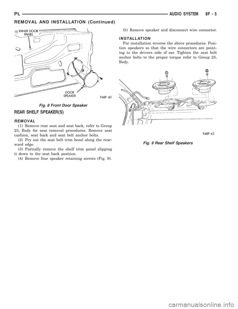
REAR SHELF SPEAKER(S)
REMOVAL
(1) Remove rear seat and seat back, refer to Group
23, Body for seat removal procedures. Remove seat
cushion, seat back and seat belt anchor bolts.
(2) Pry out the seat belt trim bezel along the rear-
ward edge.
(3) Partially remove the shelf trim panel slipping
it down to the seat back position.
(4) Remove four speaker retaining screws (Fig. 9).(5) Remove speaker and disconnect wire connector.
INSTALLATION
For installation reverse the above procedures. Posi-
tion speakers so that the wire connectors are point-
ing to the drivers side of car. Tighten the seat belt
anchor bolts to the proper torque refer to Group 23,
Body.
Fig. 8 Front Door Speaker
Fig. 9 Rear Shelf Speakers
PLAUDIO SYSTEM 8F - 5
REMOVAL AND INSTALLATION (Continued)
Page 392 of 1200
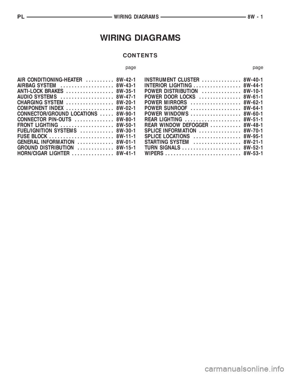
WIRING DIAGRAMS
CONTENTS
page page
AIR CONDITIONING-HEATER.......... 8W-42-1
AIRBAG SYSTEM................... 8W-43-1
ANTI-LOCK BRAKES................. 8W-35-1
AUDIO SYSTEMS................... 8W-47-1
CHARGING SYSTEM................. 8W-20-1
COMPONENT INDEX................. 8W-02-1
CONNECTOR/GROUND LOCATIONS..... 8W-90-1
CONNECTOR PIN-OUTS.............. 8W-80-1
FRONT LIGHTING................... 8W-50-1
FUEL/IGNITION SYSTEMS............ 8W-30-1
FUSE BLOCK....................... 8W-11-1
GENERAL INFORMATION............. 8W-01-1
GROUND DISTRIBUTION............. 8W-15-1
HORN/CIGAR LIGHTER............... 8W-41-1INSTRUMENT CLUSTER.............. 8W-40-1
INTERIOR LIGHTING................. 8W-44-1
POWER DISTRIBUTION.............. 8W-10-1
POWER DOOR LOCKS............... 8W-61-1
POWER MIRRORS.................. 8W-62-1
POWER SUNROOF.................. 8W-64-1
POWER WINDOWS.................. 8W-60-1
REAR LIGHTING.................... 8W-51-1
REAR WINDOW DEFOGGER........... 8W-48-1
SPLICE INFORMATION............... 8W-70-1
SPLICE LOCATIONS................. 8W-95-1
STARTING SYSTEM................. 8W-21-1
TURN SIGNALS..................... 8W-52-1
WIPERS........................... 8W-53-1
PLWIRING DIAGRAMS 8W - 1
Page 397 of 1200
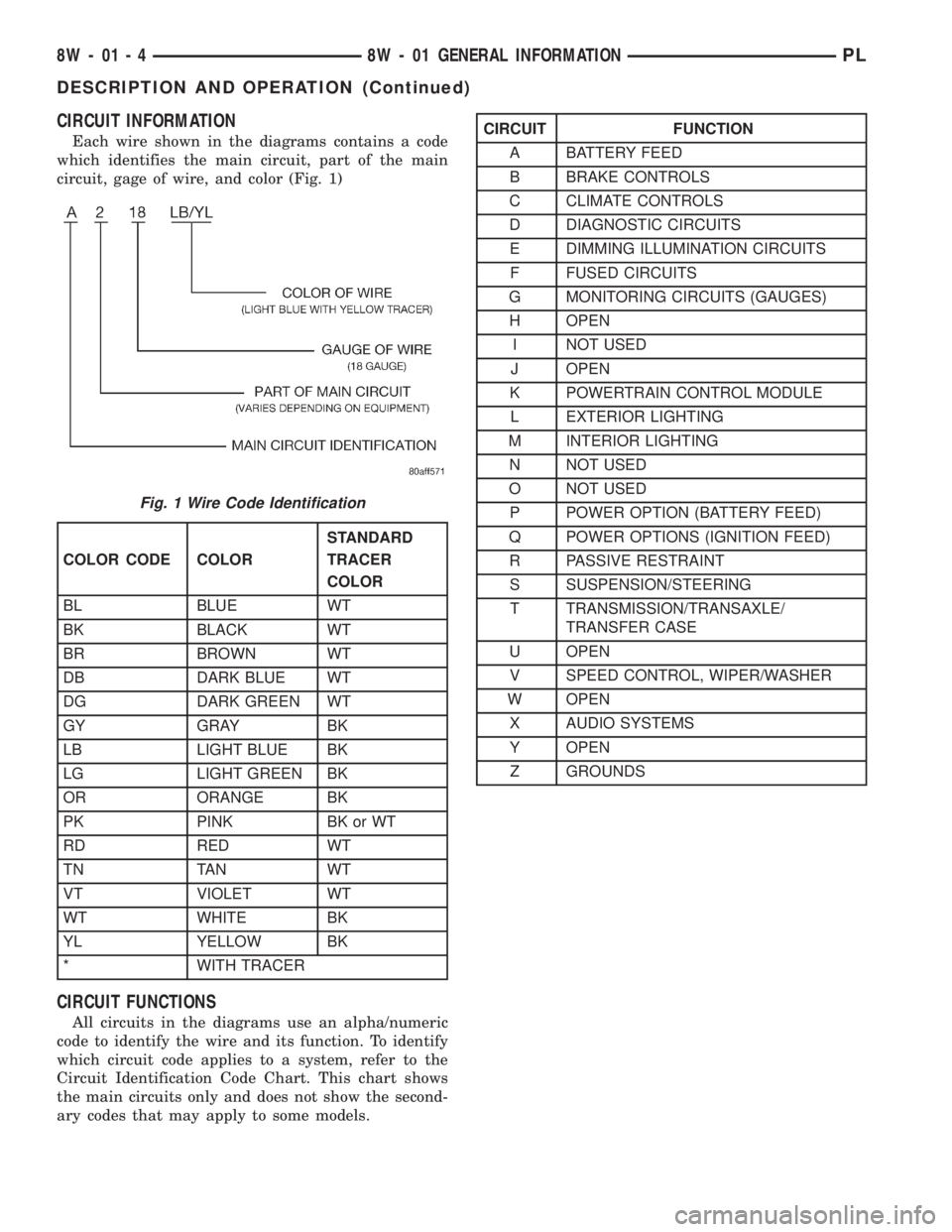
CIRCUIT INFORMATION
Each wire shown in the diagrams contains a code
which identifies the main circuit, part of the main
circuit, gage of wire, and color (Fig. 1)
CIRCUIT FUNCTIONS
All circuits in the diagrams use an alpha/numeric
code to identify the wire and its function. To identify
which circuit code applies to a system, refer to the
Circuit Identification Code Chart. This chart shows
the main circuits only and does not show the second-
ary codes that may apply to some models.
Fig. 1 Wire Code Identification
COLOR CODE COLORSTANDARD
TRACER
COLOR
BL BLUE WT
BK BLACK WT
BR BROWN WT
DB DARK BLUE WT
DG DARK GREEN WT
GY GRAY BK
LB LIGHT BLUE BK
LG LIGHT GREEN BK
OR ORANGE BK
PK PINK BK or WT
RD RED WT
TN TAN WT
VT VIOLET WT
WT WHITE BK
YL YELLOW BK
* WITH TRACER
CIRCUIT FUNCTION
A BATTERY FEED
B BRAKE CONTROLS
C CLIMATE CONTROLS
D DIAGNOSTIC CIRCUITS
E DIMMING ILLUMINATION CIRCUITS
F FUSED CIRCUITS
G MONITORING CIRCUITS (GAUGES)
H OPEN
I NOT USED
J OPEN
K POWERTRAIN CONTROL MODULE
L EXTERIOR LIGHTING
M INTERIOR LIGHTING
N NOT USED
O NOT USED
P POWER OPTION (BATTERY FEED)
Q POWER OPTIONS (IGNITION FEED)
R PASSIVE RESTRAINT
S SUSPENSION/STEERING
T TRANSMISSION/TRANSAXLE/
TRANSFER CASE
U OPEN
V SPEED CONTROL, WIPER/WASHER
W OPEN
X AUDIO SYSTEMS
Y OPEN
Z GROUNDS
8W - 01 - 4 8W - 01 GENERAL INFORMATIONPL
DESCRIPTION AND OPERATION (Continued)
Page 530 of 1200
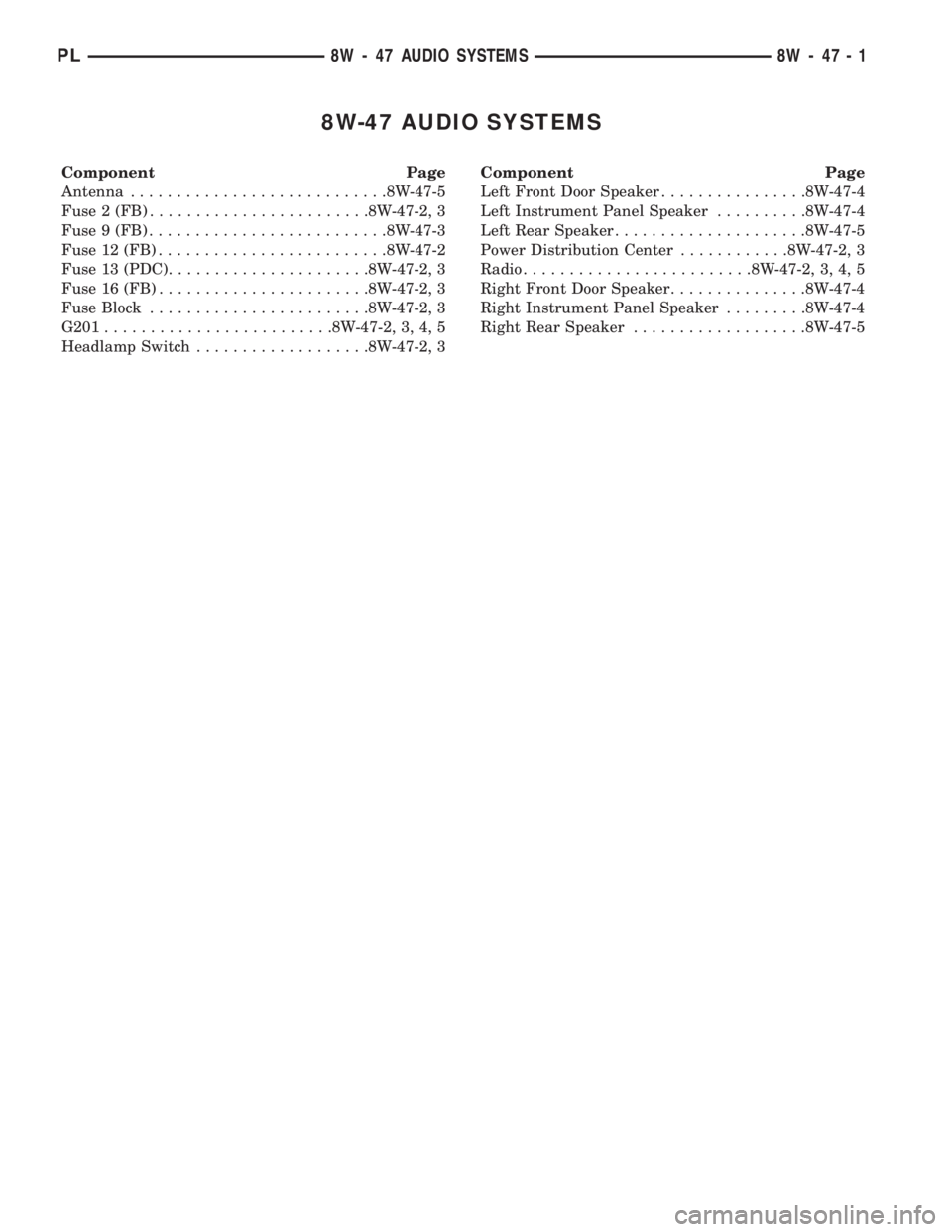
8W-47 AUDIO SYSTEMS
Component Page
Antenna............................8W-47-5
Fuse 2 (FB)........................8W-47-2, 3
Fuse 9 (FB)..........................8W-47-3
Fuse 12 (FB).........................8W-47-2
Fuse 13 (PDC)......................8W-47-2, 3
Fuse 16 (FB).......................8W-47-2, 3
Fuse Block........................8W-47-2, 3
G201.........................8W-47-2, 3, 4, 5
Headlamp Switch...................8W-47-2, 3Component Page
Left Front Door Speaker................8W-47-4
Left Instrument Panel Speaker..........8W-47-4
Left Rear Speaker.....................8W-47-5
Power Distribution Center............8W-47-2, 3
Radio.........................8W-47-2, 3, 4, 5
Right Front Door Speaker...............8W-47-4
Right Instrument Panel Speaker.........8W-47-4
Right Rear Speaker...................8W-47-5
PL8W - 47 AUDIO SYSTEMS 8W - 47 - 1
Page 531 of 1200

10A
FUSE
13
13 14
BATT A0
16
3616FUSE
10A
RUN-ACC A31BATT A3
15A
FUSE
2
222
PARK
LAMP
SWITCH
OUTPUT FUSED
IGN.
(RUN-ACC)
GROUND FUSED
B(+)FUSED
PANEL
LAMPS
DIMMER
SWITCH
SIGNAL L7
20
BK/YL
S218
L7
20
BK/YL
L7
20
BK/YL
F33
20
PK/RD
E2
20
OR
S210
E2
22
OR
X12
18
RD/WT
M1
18
PK
M1
22
PK
M1
22
PK
OTHERS
S203
13C103
6C27C25C2
Z9
14
BK
HEADLAMP
SWITCH
0 OFF
1 PARK
2 HEAD
9
4
G201
4C2
RADIO
BLOCK FUSE FUSE
BLOCK
TN20 E1
1
12
32
4A
FUSE
12
POWER
DISTRIBUTION
CENTER
2
1 0
RKE/
BUILT-UP-EXPORT (8W-10-5)(8W-10-8)
(8W-10-5)
(8W-10-6)
(8W-10-13)(8W-11-20) (8W-11-7)
(8W-11-8)
(8W-11-17)
(8W-11-18) (8W-11-2)
(8W-11-3)
(8W-11-2)
(8W-11-3) (8W-10-9)
(8W-15-7)
(8W-15-8)(8W-50-2)
(8W-50-3)
(8W-10-13)
(8W-11-17)
(8W-11-18) (8W-11-7)
(8W-11-8)
8W - 47 - 2 8W-47 AUDIO SYSTEM
LHDPL
J988W-18298