clock reset DODGE NEON 1999 Service Repair Manual
[x] Cancel search | Manufacturer: DODGE, Model Year: 1999, Model line: NEON, Model: DODGE NEON 1999Pages: 1200, PDF Size: 35.29 MB
Page 64 of 1200

mount and all tension is relieved from the spring
compressors.
(11) Install the strut assembly back into the vehi-
cle. Refer to Strut Assembly Removal in Servicing
Rear Struts in this section of the service manual.
(12) Check and reset rear wheel TOE to specifica-
tions if required.
STABILIZER BAR BUSHINGS
(1) If stabilizer bar to frame rail bushings require
replacement at time of inspection, install new bush-
ings before installing stabilizer bar. Bushings are
replaced by opening slit on bushings and peeling
them off stabilizer bar. Install new bushings on sta-
bilizer bar, by spreading bushing at slit and forcing
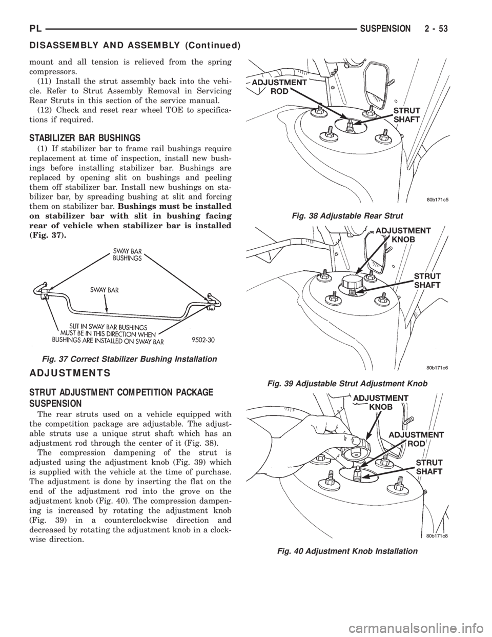
them on stabilizer bar.Bushings must be installed
on stabilizer bar with slit in bushing facing
rear of vehicle when stabilizer bar is installed
(Fig. 37).
ADJUSTMENTS
STRUT ADJUSTMENT COMPETITION PACKAGE
SUSPENSION
The rear struts used on a vehicle equipped with
the competition package are adjustable. The adjust-
able struts use a unique strut shaft which has an
adjustment rod through the center of it (Fig. 38).
The compression dampening of the strut is
adjusted using the adjustment knob (Fig. 39) which
is supplied with the vehicle at the time of purchase.
The adjustment is done by inserting the flat on the
end of the adjustment rod into the grove on the
adjustment knob (Fig. 40). The compression dampen-
ing is increased by rotating the adjustment knob
(Fig. 39) in a counterclockwise direction and
decreased by rotating the adjustment knob in a clock-
wise direction.
Fig. 37 Correct Stabilizer Bushing Installation
Fig. 38 Adjustable Rear Strut
Fig. 39 Adjustable Strut Adjustment Knob
Fig. 40 Adjustment Knob Installation
PLSUSPENSION 2 - 53
DISASSEMBLY AND ASSEMBLY (Continued)
Page 288 of 1200

AUDIO SYSTEM
CONTENTS
page page
GENERAL INFORMATION
INTRODUCTION......................... 1
DESCRIPTION AND OPERATION
INTERFERENCE ELIMINATION.............. 1
DIAGNOSIS AND TESTING
ANTENNA.............................. 3
AUDIO DIAGNOSTIC TEST PROCEDURES..... 1BENCH TEST FOR ANTENNA MALFUNCTION . . 3
REMOVAL AND INSTALLATION
ANTENNA.............................. 3
FRONT DOOR SPEAKER................... 4
INSTRUMENT PANEL SPEAKER............. 4
RADIO................................. 4
REAR SHELF SPEAKER(S)................. 5
GENERAL INFORMATION
INTRODUCTION
Operating instructions for the factory installed
audio systems can be found in the Owner's Manual
provided with the vehicle.
The vehicles are equipped with an Interior (Igni-
tion Off Draw) fuse in the Power Distribution Center
located in the engine compartment. After the Interior
(IOD) fuse or battery has been disconnected the clock
will require resetting.
DESCRIPTION AND OPERATION
INTERFERENCE ELIMINATION
The radio utilizes a ground wire plugged on to a
blade terminal and is bolted to the radio chassis.
Both connector and terminal should be securely
attached. The engine has three separate ground
straps to suppress ignition noise which may interfere
with radio reception.
²Left engine mount clip on strap
²Engine to shock tower reinforcement
²Rear strut to body, clip-on strap
Inductive type spark plug cables in the high ten-
sion circuit of the ignition system complete the inter-
ference suppression. Faulty or deteriorated spark
plug wires should be replaced.
In addition, there is a capacitor mounted on the
cylinder head which also helps suppress ignition
noise.
DIAGNOSIS AND TESTING
AUDIO DIAGNOSTIC TEST PROCEDURES
CAUTION: The CD player will only operate between
approximate temperatures of -23ÉC and +65ÉC (-10ÉF
and +145ÉF).
Whenever a radio malfunction occurs;
(1) First check FUSES:
(a) Power Distribution Center (PDC), Interior
lamp fuse, M1 - Radio Memory Feed
(b) Fuse Block:
(I) Fuse 12, Illumination in the fuse block
(II) Fuse 16, Ignition feed in the fuse block
NOTE: The vehicles are shipped with the INTERIOR
LAMP fuse disconnected.
(2) Verify, the radio wire harness are properly con-
nected before starting normal diagnosis and repair
procedures. Refer to Audio Diagnosis table and/or
Group 8W, Wiring Diagrams, Radio Section.
PLAUDIO SYSTEM 8F - 1
Page 305 of 1200

(c) If continuity is OK between cavity 62 and
cavity 1, repair open circuit between cavity 2 of the
stop lamp switch connector and ground.
(6) Using an ohmmeter, check continuity from cav-
ity 76 on PCM connector to ground with the trans-
mission in park or neutral. If no continuity, test TRS/
Park-Neutral switch and switch wiring
(7) Turn speed control and ignition switch OFF.
(8) Unplug the BLACK 40-way connector from the
Powertrain Control Module (PCM)
(9) Using an ohmmeter, check continuity from cav-
ity 3 of servo connector to cavity 5 on the PCM con-
nector.
(a) If continuity is OK, replace PCM. Check cir-
cuit for short to ground before replacing PCM.
(b) If no continuity, remove stop lamp switch
and conduct Stop Lamp Switch Test. If test fails,
adjust or replace as necessary.
(c) If switch passes, measure continuity from
cavity 4 of stop lamp switch connector to cavity 3
of servo connector. Repair open circuit if necessary.
(d) If continuity is OK, measure continuity from
cavity 3 of stop lamp switch to cavity 5 of PCM
connector. Repair open circuit as necessary.
(e) Install PCM connectors onto PCM and speed
control servo connector to servo.
VACUUM SUPPLY TEST
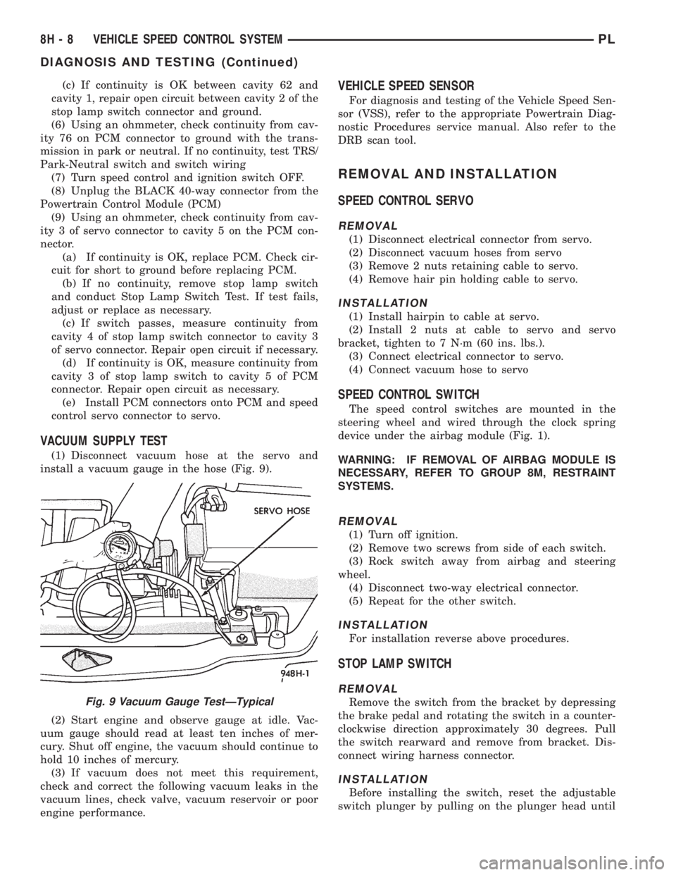
(1) Disconnect vacuum hose at the servo and
install a vacuum gauge in the hose (Fig. 9).
(2) Start engine and observe gauge at idle. Vac-
uum gauge should read at least ten inches of mer-
cury. Shut off engine, the vacuum should continue to
hold 10 inches of mercury.
(3) If vacuum does not meet this requirement,
check and correct the following vacuum leaks in the
vacuum lines, check valve, vacuum reservoir or poor
engine performance.
VEHICLE SPEED SENSOR
For diagnosis and testing of the Vehicle Speed Sen-
sor (VSS), refer to the appropriate Powertrain Diag-
nostic Procedures service manual. Also refer to the
DRB scan tool.
REMOVAL AND INSTALLATION
SPEED CONTROL SERVO
REMOVAL
(1) Disconnect electrical connector from servo.
(2) Disconnect vacuum hoses from servo
(3) Remove 2 nuts retaining cable to servo.
(4) Remove hair pin holding cable to servo.
INSTALLATION
(1) Install hairpin to cable at servo.
(2) Install 2 nuts at cable to servo and servo
bracket, tighten to 7 N´m (60 ins. lbs.).
(3) Connect electrical connector to servo.
(4) Connect vacuum hose to servo
SPEED CONTROL SWITCH
The speed control switches are mounted in the
steering wheel and wired through the clock spring
device under the airbag module (Fig. 1).
WARNING: IF REMOVAL OF AIRBAG MODULE IS
NECESSARY, REFER TO GROUP 8M, RESTRAINT
SYSTEMS.
REMOVAL
(1) Turn off ignition.
(2) Remove two screws from side of each switch.
(3) Rock switch away from airbag and steering
wheel.
(4) Disconnect two-way electrical connector.
(5) Repeat for the other switch.
INSTALLATION
For installation reverse above procedures.
STOP LAMP SWITCH
REMOVAL
Remove the switch from the bracket by depressing
the brake pedal and rotating the switch in a counter-
clockwise direction approximately 30 degrees. Pull
the switch rearward and remove from bracket. Dis-
connect wiring harness connector.
INSTALLATION
Before installing the switch, reset the adjustable
switch plunger by pulling on the plunger head until
Fig. 9 Vacuum Gauge TestÐTypical
8H - 8 VEHICLE SPEED CONTROL SYSTEMPL
DIAGNOSIS AND TESTING (Continued)
Page 943 of 1200

CAUTION: Do not install steering wheel onto shaft
of steering column assembly by driving it onto the
shaft. Pull steering wheel down onto steering col-
umn shaft using ONLY the steering wheel retaining
nut.
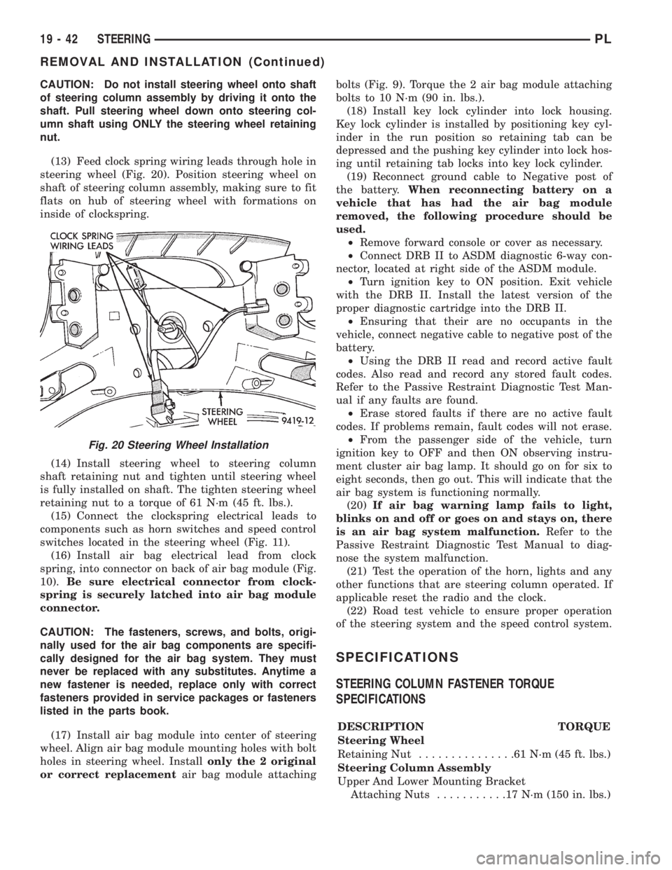
(13) Feed clock spring wiring leads through hole in
steering wheel (Fig. 20). Position steering wheel on
shaft of steering column assembly, making sure to fit
flats on hub of steering wheel with formations on
inside of clockspring.
(14) Install steering wheel to steering column
shaft retaining nut and tighten until steering wheel
is fully installed on shaft. The tighten steering wheel
retaining nut to a torque of 61 N´m (45 ft. lbs.).
(15) Connect the clockspring electrical leads to
components such as horn switches and speed control
switches located in the steering wheel (Fig. 11).
(16) Install air bag electrical lead from clock
spring, into connector on back of air bag module (Fig.
10).Be sure electrical connector from clock-
spring is securely latched into air bag module
connector.
CAUTION: The fasteners, screws, and bolts, origi-
nally used for the air bag components are specifi-
cally designed for the air bag system. They must
never be replaced with any substitutes. Anytime a
new fastener is needed, replace only with correct
fasteners provided in service packages or fasteners
listed in the parts book.
(17) Install air bag module into center of steering
wheel. Align air bag module mounting holes with bolt
holes in steering wheel. Installonly the 2 original
or correct replacementair bag module attachingbolts (Fig. 9). Torque the 2 air bag module attaching
bolts to 10 N´m (90 in. lbs.).
(18) Install key lock cylinder into lock housing.
Key lock cylinder is installed by positioning key cyl-
inder in the run position so retaining tab can be
depressed and the pushing key cylinder into lock hos-
ing until retaining tab locks into key lock cylinder.
(19) Reconnect ground cable to Negative post of
the battery.When reconnecting battery on a
vehicle that has had the air bag module
removed, the following procedure should be
used.
²Remove forward console or cover as necessary.
²Connect DRB II to ASDM diagnostic 6-way con-
nector, located at right side of the ASDM module.
²Turn ignition key to ON position. Exit vehicle
with the DRB II. Install the latest version of the
proper diagnostic cartridge into the DRB II.
²Ensuring that their are no occupants in the
vehicle, connect negative cable to negative post of the
battery.
²Using the DRB II read and record active fault
codes. Also read and record any stored fault codes.
Refer to the Passive Restraint Diagnostic Test Man-
ual if any faults are found.
²Erase stored faults if there are no active fault
codes. If problems remain, fault codes will not erase.
²From the passenger side of the vehicle, turn
ignition key to OFF and then ON observing instru-
ment cluster air bag lamp. It should go on for six to
eight seconds, then go out. This will indicate that the
air bag system is functioning normally.
(20)If air bag warning lamp fails to light,
blinks on and off or goes on and stays on, there
is an air bag system malfunction.Refer to the
Passive Restraint Diagnostic Test Manual to diag-
nose the system malfunction.
(21) Test the operation of the horn, lights and any
other functions that are steering column operated. If
applicable reset the radio and the clock.
(22) Road test vehicle to ensure proper operation
of the steering system and the speed control system.
SPECIFICATIONS
STEERING COLUMN FASTENER TORQUE
SPECIFICATIONS
DESCRIPTION TORQUE
Steering Wheel
Retaining Nut...............61N´m(45ft.lbs.)
Steering Column Assembly
Upper And Lower Mounting Bracket
Attaching Nuts...........17N´m(150 in. lbs.)
Fig. 20 Steering Wheel Installation
19 - 42 STEERINGPL
REMOVAL AND INSTALLATION (Continued)