length DODGE NEON 1999 Service Repair Manual
[x] Cancel search | Manufacturer: DODGE, Model Year: 1999, Model line: NEON, Model: DODGE NEON 1999Pages: 1200, PDF Size: 35.29 MB
Page 60 of 1200
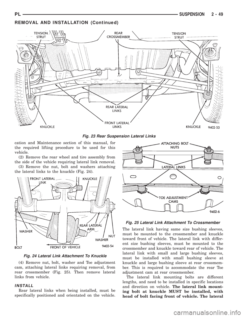
cation and Maintenance section of this manual, for
the required lifting procedure to be used for this
vehicle.
(2) Remove the rear wheel and tire assembly from
the side of the vehicle requiring lateral link removal.
(3) Remove the nut, bolt and washers attaching
the lateral links to the knuckle (Fig. 24).
(4) Remove nut, bolt, washer and Toe adjustment
cam, attaching lateral links requiring removal, from
rear crossmember (Fig. 25). Then remove lateral
links from vehicle.
INSTALL
Rear lateral links when being installed, must be
specifically positioned and orientated on the vehicle.The lateral link having same size bushing sleeves,
must be mounted to the crossmember and knuckle
toward front of vehicle. The lateral link with differ-
ent size bushing sleeves, must be mounted to the
crossmember and knuckle toward rear of vehicle. The
lateral link with small and large bushing sleeves,
must be installed with small bushing sleeve at
knuckle and large bushing sleeve at rear crossmem-
ber. This is required to accommodate the rear Toe
adjustment cam at rear crossmember.
The lateral link mounting bolts are different
lengths, and need to be installed in specific locations
and direction on vehicle.The lateral link mount-
ing bolt at knuckle MUST be installed, with
head of bolt facing front of vehicle. The lateral
Fig. 23 Rear Suspension Lateral Links
Fig. 24 Lateral Link Attachment To Knuckle
Fig. 25 Lateral Link Attachment To Crossmember
PLSUSPENSION 2 - 49
REMOVAL AND INSTALLATION (Continued)
Page 66 of 1200
DIFFERENTIAL AND DRIVELINE
CONTENTS
page page
GENERAL INFORMATION
FRONT DRIVESHAFTS.................... 1
DIAGNOSIS AND TESTING
DRIVESHAFT DIAGNOSIS.................. 2
REMOVAL AND INSTALLATION
FRONT DRIVESHAFTS.................... 2
DISASSEMBLY AND ASSEMBLY
DRIVESHAFT RECONDITION............... 7INNER TRIPOD JOINT SEAL BOOT.......... 9
OUTER C/V JOINT SEAL BOOT............ 13
SPECIFICATIONS
TORQUE.............................. 16
SPECIAL TOOLS
DRIVESHAFT........................... 16
GENERAL INFORMATION
FRONT DRIVESHAFTS
Vehicles equipped with either an automatic or
manual transmission use the unequal±length drive-
shaft system.
Vehicles equipped with automatic transaxles use a
solid short interconnecting shaft on the left side. The
right side of the vehicle uses a longer solid intercon-
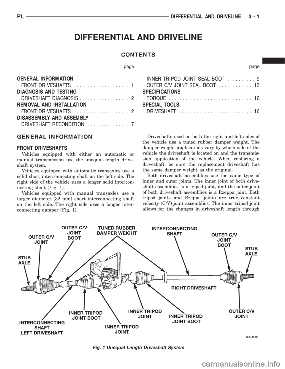
necting shaft (Fig. 1).
Vehicles equipped with manual transaxles use a
larger diameter (32 mm) short interconnecting shaft
on the left side. The right side uses a longer inter-
connecting damper (Fig. 1).Driveshafts used on both the right and left sides of
the vehicle use a tuned rubber damper weight. The
damper weight applications vary by which side of the
vehicle the driveshaft is located on and the transmis-
sion application of the vehicle. When replacing a
driveshaft, be sure the replacement driveshaft has
the same damper weight as the original.
Both driveshaft assemblies use the same type of
inner and outer joints. The inner joint of both drive-
shaft assemblies is a tripod joint, and the outer joint
of both driveshaft assemblies is a Rzeppa joint. Both
tripod joints and Rzeppa joints are true constant
velocity (C/V) joint assemblies. The inner tripod joint
allows for the changes in driveshaft length through
Fig. 1 Unequal Length Driveshaft System
PLDIFFERENTIAL AND DRIVELINE 3 - 1
Page 77 of 1200
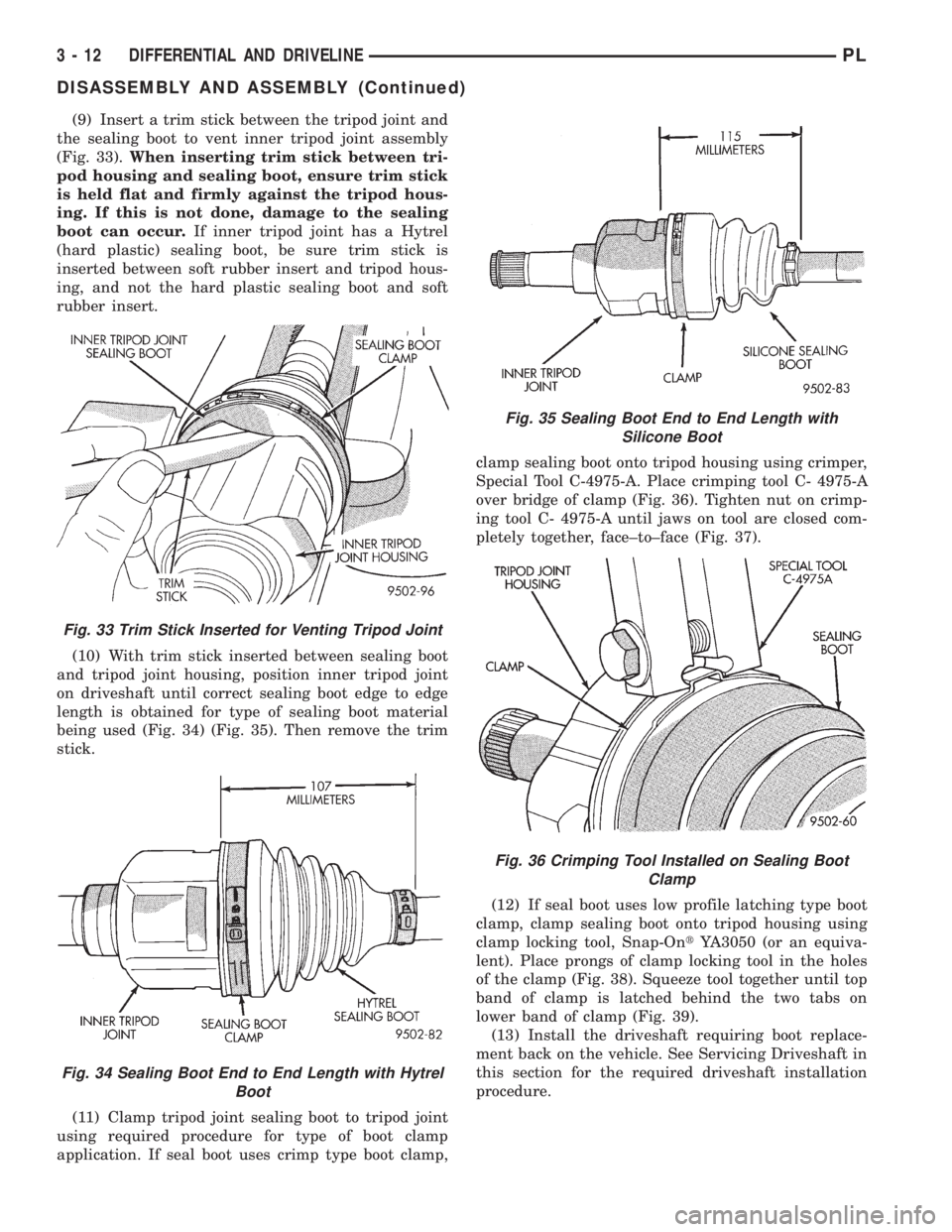
(9) Insert a trim stick between the tripod joint and
the sealing boot to vent inner tripod joint assembly
(Fig. 33).When inserting trim stick between tri-
pod housing and sealing boot, ensure trim stick
is held flat and firmly against the tripod hous-
ing. If this is not done, damage to the sealing
boot can occur.If inner tripod joint has a Hytrel
(hard plastic) sealing boot, be sure trim stick is
inserted between soft rubber insert and tripod hous-
ing, and not the hard plastic sealing boot and soft
rubber insert.
(10) With trim stick inserted between sealing boot
and tripod joint housing, position inner tripod joint
on driveshaft until correct sealing boot edge to edge
length is obtained for type of sealing boot material
being used (Fig. 34) (Fig. 35). Then remove the trim
stick.
(11) Clamp tripod joint sealing boot to tripod joint
using required procedure for type of boot clamp
application. If seal boot uses crimp type boot clamp,clamp sealing boot onto tripod housing using crimper,
Special Tool C-4975-A. Place crimping tool C- 4975-A
over bridge of clamp (Fig. 36). Tighten nut on crimp-
ing tool C- 4975-A until jaws on tool are closed com-
pletely together, face±to±face (Fig. 37).
(12) If seal boot uses low profile latching type boot
clamp, clamp sealing boot onto tripod housing using
clamp locking tool, Snap-OntYA3050 (or an equiva-
lent). Place prongs of clamp locking tool in the holes
of the clamp (Fig. 38). Squeeze tool together until top
band of clamp is latched behind the two tabs on
lower band of clamp (Fig. 39).
(13) Install the driveshaft requiring boot replace-
ment back on the vehicle. See Servicing Driveshaft in
this section for the required driveshaft installation
procedure.
Fig. 33 Trim Stick Inserted for Venting Tripod Joint
Fig. 34 Sealing Boot End to End Length with Hytrel
Boot
Fig. 35 Sealing Boot End to End Length with
Silicone Boot
Fig. 36 Crimping Tool Installed on Sealing Boot
Clamp
3 - 12 DIFFERENTIAL AND DRIVELINEPL
DISASSEMBLY AND ASSEMBLY (Continued)
Page 128 of 1200
(9) Position master cylinder on studs of power
brake unit, aligning push rod on power brake vac-
uum booster with master cylinder push rod.
(10) Install the 2 master cylinder mounting nuts
(Fig. 117) and torque to 28 N´m (250 in. lbs.) torque.
(11) Connect brake tubes to master cylinder pri-
mary and secondary ports (Fig. 115) and (Fig. 116).
Torque all tube nuts to 17 N´m (145 in. lbs.) torque.
(12) Reconnect wiring connector to fluid level sen-
sor.
(13) Adjust stop lamp switch as necessary.
(14) Bleed brake system.
CHASSIS TUBES AND HOSES
Always use Mopar replacement brake hose assem-
blies to ensure quality, correct length and superior
fatigue life. Care should be taken to make sure that
the tube and hose mating surfaces are clean and free
from nicks and burrs.Hose assemblies for each
brake are unique and not interchangeable.
Use new copper seal washers on all connections
using Banjo Bolts and tighten all fittings to their
specified torques.
The flexible front hydraulic brake hose should
always be installed on the vehicle by first attaching
the Banjo connector to the caliper assembly. Then
bolt the intermediate hose bracket to the strut
assembly allowing the bracket to position the hose to
prevent twisting. Attach the hose to brake tubing,
before attaching to front frame rail. Then tighten all
brake line fittings to specified torque.
On vehicles equipped with rear drum brakes,
install rear brake hoses first to wheel cylinders and
rear struts and then attach hose bracket to body. On
vehicles equipped with rear disc brakes, attach brake
hoses to calipers and struts first and then attach
brake hose bracket to body. Following this procedure
will reduce potential for twisting brake during instal-
lation procedure.
Only double wall 4.75mm (3/16 in.) steel brake line
tubing, with Al- Rich/ZN-AL alloy coating should be
used for replacement. Care must be taken when
replacing brake tubing, to be sure the proper bending
and flaring tools and procedures are used to avoid
kinking. Do not route the tubes against sharp edges,
moving components or into hot areas. All tubes
should be properly attached with recommended
retaining clips.
PROPORTIONING VALVE (BASE BRAKES)
CAUTION: Proportioning valves (Fig. 125) should
never be disassembled.
There are two proportioning valve assemblies used
in each vehicle. Due to different thread sizes, each
proportioning valve has a different part number. Dur-ing any service procedures identify the proportioning
valve assemblies by supplier part number and or the
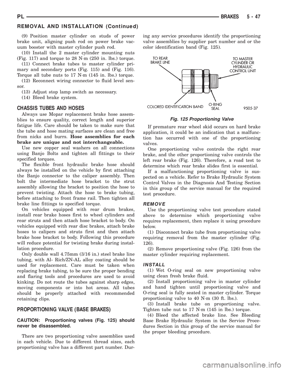
color identification band (Fig. 125).
If premature rear wheel skid occurs on hard brake
application, it could be an indication that a malfunc-
tion has occurred with one of the proportioning
valves.
One proportioning valve controls the right rear
brake, and the other proportioning valve controls the
left rear brake (Fig. 126). Therefore, a road test to
determine which rear brake slides first is essential.
If a malfunctioning proportioning valve is sus-
pected on a vehicle. Refer to Brake Hydraulic System
Control Valves in the Diagnosis And Testing Section
in this group of the service manual for the required
test procedure.
REMOVE
Use the proportioning valve test procedure stated
above to determine which proportioning valve
requires replacement, then replace it using procedure
below.
(1) Disconnect brake tube from proportioning valve
requiring removal from the master cylinder (Fig.
126).
(2) Remove proportioning valve (Fig. 126) from the
master cylinder requiring replacement.
INSTALL
(1) Wet O-ring seal on new proportioning valve
using clean fresh brake fluid.
(2) Install proportioning valve in master cylinder
and hand tighten until proportioning valve and
O-ring seal is fully seated in master cylinder. Torque
proportioning valve to 40 N´m (30 ft. lbs.).
(3) Install brake tube on proportioning valve.
Tighten tube nut to 17 N´m (145 in lbs.) torque.
(4) Bleed the affected brake line. See Bleeding
Base Brake Hydraulic System in the Service Proce-
dures Section in this group of the service manual for
the proper bleeding procedure.
Fig. 125 Proportioning Valve
PLBRAKES 5 - 47
REMOVAL AND INSTALLATION (Continued)
Page 136 of 1200
to one-half specified torque. Then repeat pattern,
fully tightening stud nuts to 135 N´m (100 ft. lbs.).
(11) Lower vehicle.
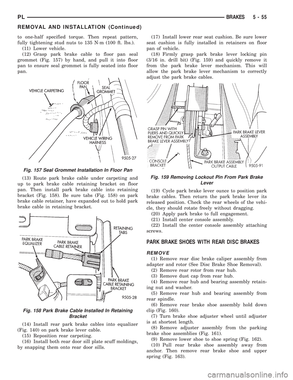
(12) Grasp park brake cable to floor pan seal
grommet (Fig. 157) by hand, and pull it into floor
pan to ensure seal grommet is fully seated into floor
pan.
(13) Route park brake cable under carpeting and
up to park brake cable retaining bracket on floor
pan. Then install park brake cable into retaining
bracket (Fig. 158). Be sure tabs (Fig. 158) on park
brake cable retainer, have expanded out to hold park
brake cable in retaining bracket.
(14) Install rear park brake cables into equalizer
(Fig. 140) on park brake lever cable.
(15) Reposition rear carpeting.
(16) Install both rear door sill plate scuff moldings,
by snapping them onto rear door sills.(17) Install lower rear seat cushion. Be sure lower
seat cushion is fully installed in retainers on floor
pan of vehicle.
(18) Firmly grasp park brake lever locking pin
(3/16 in. drill bit) (Fig. 159) and quickly remove it
from the park brake lever mechanism. This will
allow the park brake lever mechanism to correctly
adjust the park brake cables.
(19) Cycle park brake lever ounce to position park
brake cables. Then return the park brake lever its
released position. Check the rear wheels of the vehi-
cle, they should rotate freely without dragging.
(20) Apply park brake to full engagement.
(21) Install center console assembly.
(22) Install the center console assembly attaching
screws.
PARK BRAKE SHOES WITH REAR DISC BRAKES
REMOVE
(1) Remove rear disc brake caliper assembly from
adapter and rotor (See Disc Brake Shoe Removal).
(2) Remove rear rotor from rear hub.
(3) Remove dust cap from rear hub.
(4) Remove rear hub and bearing assembly retain-
ing nut and washer.
(5) Remove rear hub and bearing assembly from
rear spindle.
(6) Remove rear brake shoe assembly hold down
clip (Fig. 160).
(7) Turn brake shoe adjuster wheel until adjuster
is at shortest length.
(8) Remove adjuster assembly from the parking
brake shoe assemblies (Fig. 161).
(9) Remove lower shoe to shoe spring (Fig. 162).
(10) Pull rear brake shoe assembly away from
anchor. Then remove rear brake shoe and upper
spring (Fig. 163).
Fig. 157 Seal Grommet Installation In Floor Pan
Fig. 158 Park Brake Cable Installed In Retaining
Bracket
Fig. 159 Removing Lockout Pin From Park Brake
Lever
PLBRAKES 5 - 55
REMOVAL AND INSTALLATION (Continued)
Page 140 of 1200
Caliper Disassembly And Re-Assembly Procedures in
Disc Brake Caliper Service in this section of the ser-
vice manual.
Check the guide pin dust boots to determine if they
are in good condition. Replace if they are damaged,
dry, or found to be brittle. Refer to Guide Pin Bush-
ing Service in Disc Brake Caliper Service in this sec-
tion of the service manual.
CALIPER GUIDE PIN BUSHING SERVICE
The double pin caliper uses a sealed for life bush-
ing and sleeve assembly. If required this assembly
can be serviced using the following procedure.
REMOVING CALIPER GUIDE PIN BUSHINGS
(1) Remove caliper from brake rotor (See Brake
Shoe Removal). Hang caliper assembly on a wire
hook away from the brake rotor.
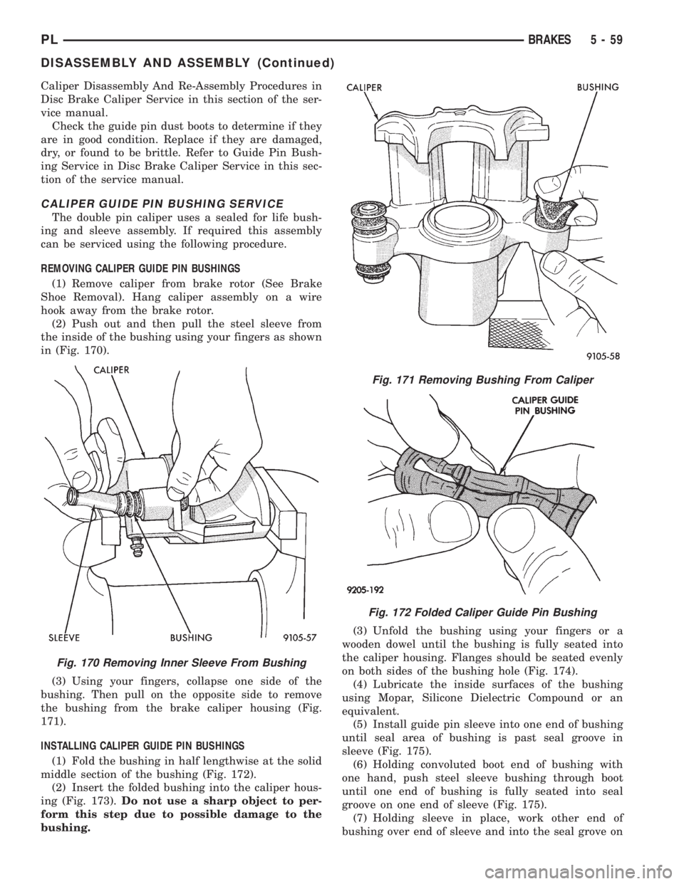
(2) Push out and then pull the steel sleeve from
the inside of the bushing using your fingers as shown
in (Fig. 170).
(3) Using your fingers, collapse one side of the
bushing. Then pull on the opposite side to remove
the bushing from the brake caliper housing (Fig.
171).
INSTALLING CALIPER GUIDE PIN BUSHINGS
(1) Fold the bushing in half lengthwise at the solid
middle section of the bushing (Fig. 172).
(2) Insert the folded bushing into the caliper hous-
ing (Fig. 173).Do not use a sharp object to per-
form this step due to possible damage to the
bushing.(3) Unfold the bushing using your fingers or a
wooden dowel until the bushing is fully seated into
the caliper housing. Flanges should be seated evenly
on both sides of the bushing hole (Fig. 174).
(4) Lubricate the inside surfaces of the bushing
using Mopar, Silicone Dielectric Compound or an
equivalent.
(5) Install guide pin sleeve into one end of bushing
until seal area of bushing is past seal groove in
sleeve (Fig. 175).
(6) Holding convoluted boot end of bushing with
one hand, push steel sleeve bushing through boot
until one end of bushing is fully seated into seal
groove on one end of sleeve (Fig. 175).
(7) Holding sleeve in place, work other end of
bushing over end of sleeve and into the seal grove on
Fig. 170 Removing Inner Sleeve From Bushing
Fig. 171 Removing Bushing From Caliper
Fig. 172 Folded Caliper Guide Pin Bushing
PLBRAKES 5 - 59
DISASSEMBLY AND ASSEMBLY (Continued)
Page 195 of 1200
During any reassembly procedures all pipe fittings
in water jacket, and waterbox require cleaning and
application of thread sealant for entire length of
threads.
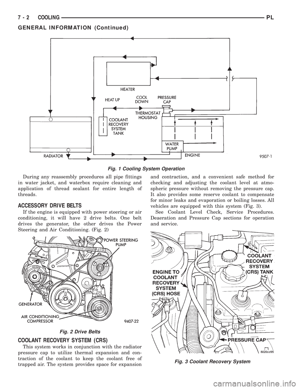
ACCESSORY DRIVE BELTS
If the engine is equipped with power steering or air
conditioning, it will have 2 drive belts. One belt
drives the generator, the other drives the Power
Steering and Air Conditioning. (Fig. 2)
COOLANT RECOVERY SYSTEM (CRS)
This system works in conjunction with the radiator
pressure cap to utilize thermal expansion and con-
traction of the coolant to keep the coolant free of
trapped air. The system provides space for expansionand contraction, and a convenient safe method for
checking and adjusting the coolant level at atmo-
spheric pressure without removing the pressure cap.
It also provides some reserve coolant to compensate
for minor leaks and evaporation or boiling losses. All
vehicles are equipped with this system (Fig. 3).
See Coolant Level Check, Service Procedures.
Deaeration and Pressure Cap sections for operation
and service.
Fig. 1 Cooling System Operation
Fig. 2 Drive Belts
Fig. 3 Coolant Recovery System
7 - 2 COOLINGPL
GENERAL INFORMATION (Continued)
Page 227 of 1200
WARNING: TO PROTECT THE HANDS FROM BAT-
TERY ACID, A SUITABLE PAIR OF HEAVY DUTY
RUBBER GLOVES, NOT THE HOUSEHOLD TYPE,
SHOULD BE WORN WHEN REMOVING OR SERVIC-
ING A BATTERY. SAFETY GLASSES ALSO SHOULD
BE WORN.
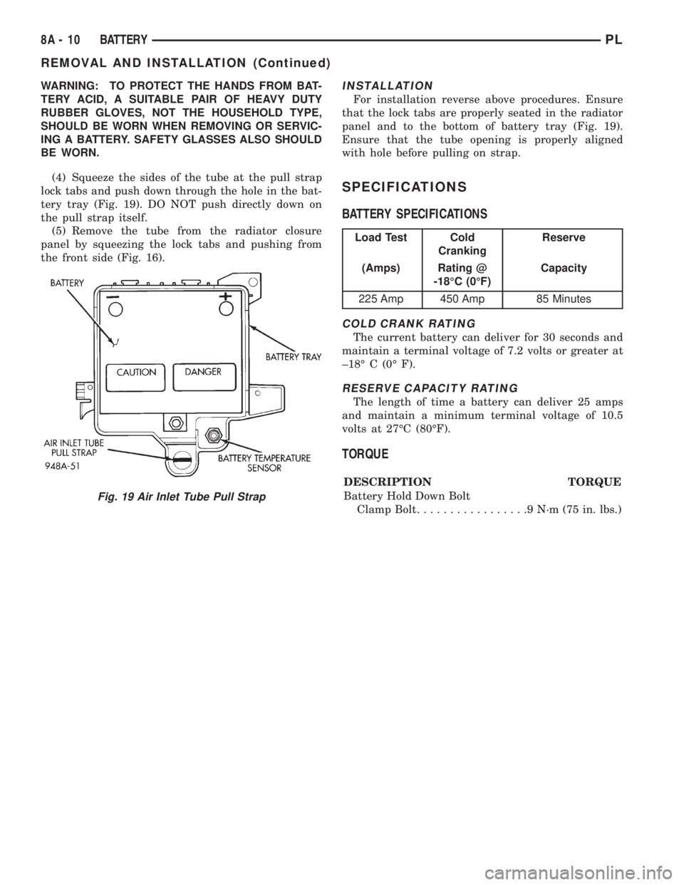
(4) Squeeze the sides of the tube at the pull strap
lock tabs and push down through the hole in the bat-
tery tray (Fig. 19). DO NOT push directly down on
the pull strap itself.
(5) Remove the tube from the radiator closure
panel by squeezing the lock tabs and pushing from
the front side (Fig. 16).INSTALLATION
For installation reverse above procedures. Ensure
that the lock tabs are properly seated in the radiator
panel and to the bottom of battery tray (Fig. 19).
Ensure that the tube opening is properly aligned
with hole before pulling on strap.
SPECIFICATIONS
BATTERY SPECIFICATIONS
COLD CRANK RATING
The current battery can deliver for 30 seconds and
maintain a terminal voltage of 7.2 volts or greater at
±18É C (0É F).
RESERVE CAPACITY RATING
The length of time a battery can deliver 25 amps
and maintain a minimum terminal voltage of 10.5
volts at 27ÉC (80ÉF).
TORQUE
DESCRIPTION TORQUE
Battery Hold Down Bolt
Clamp Bolt.................9N´m(75in.lbs.)
Fig. 19 Air Inlet Tube Pull Strap
Load Test Cold
CrankingReserve
(Amps) Rating @
-18ÉC (0ÉF)Capacity
225 Amp 450 Amp 85 Minutes
8A - 10 BATTERYPL
REMOVAL AND INSTALLATION (Continued)
Page 290 of 1200
ANTENNA
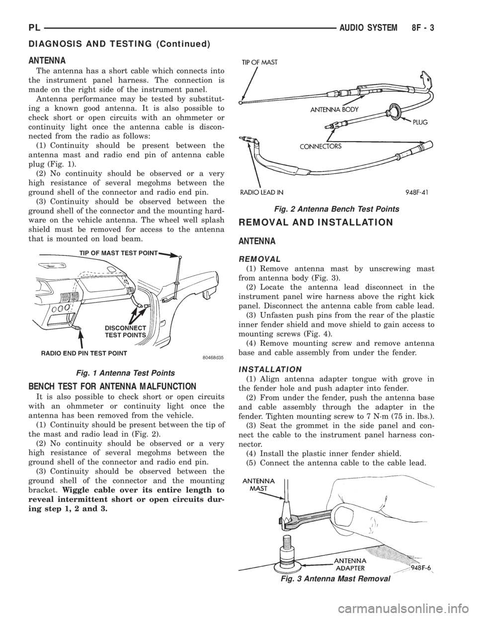
The antenna has a short cable which connects into
the instrument panel harness. The connection is
made on the right side of the instrument panel.
Antenna performance may be tested by substitut-
ing a known good antenna. It is also possible to
check short or open circuits with an ohmmeter or
continuity light once the antenna cable is discon-
nected from the radio as follows:
(1) Continuity should be present between the
antenna mast and radio end pin of antenna cable
plug (Fig. 1).
(2) No continuity should be observed or a very
high resistance of several megohms between the
ground shell of the connector and radio end pin.
(3) Continuity should be observed between the
ground shell of the connector and the mounting hard-
ware on the vehicle antenna. The wheel well splash
shield must be removed for access to the antenna
that is mounted on load beam.
BENCH TEST FOR ANTENNA MALFUNCTION
It is also possible to check short or open circuits
with an ohmmeter or continuity light once the
antenna has been removed from the vehicle.
(1) Continuity should be present between the tip of
the mast and radio lead in (Fig. 2).
(2) No continuity should be observed or a very
high resistance of several megohms between the
ground shell of the connector and radio end pin.
(3) Continuity should be observed between the
ground shell of the connector and the mounting
bracket.Wiggle cable over its entire length to
reveal intermittent short or open circuits dur-
ing step 1, 2 and 3.
REMOVAL AND INSTALLATION
ANTENNA
REMOVAL
(1) Remove antenna mast by unscrewing mast
from antenna body (Fig. 3).
(2) Locate the antenna lead disconnect in the
instrument panel wire harness above the right kick
panel. Disconnect the antenna cable from cable lead.
(3) Unfasten push pins from the rear of the plastic
inner fender shield and move shield to gain access to
mounting screws (Fig. 4).
(4) Remove mounting screw and remove antenna
base and cable assembly from under the fender.
INSTALLATION
(1) Align antenna adapter tongue with grove in
the fender hole and push adapter into fender.
(2) From under the fender, push the antenna base
and cable assembly through the adapter in the
fender. Tighten mounting screw to 7 N´m (75 in. lbs.).
(3) Seat the grommet in the side panel and con-
nect the cable to the instrument panel harness con-
nector.
(4) Install the plastic inner fender shield.
(5) Connect the antenna cable to the cable lead.
Fig. 2 Antenna Bench Test Points
Fig. 3 Antenna Mast Removal
Fig. 1 Antenna Test Points
PLAUDIO SYSTEM 8F - 3
DIAGNOSIS AND TESTING (Continued)
Page 303 of 1200
OVERSHOOT/UNDERSHOOT FOLLOWING SPEED
CONTROL SET
If the operator repeatedly presses and releases the
set button with their foot off of the accelerator (a ªlift
foot setº to begin speed control operation), the vehicle
may accelerate and exceed the desired set speed by
up to 5 MPH (8 km/h) and then decelerate to less
than the desired set speed before finally achieving
the desired set speed.
The Speed Control has an adaptive strategy that
compensates for vehicle-to-vehicle variations in speed
control cable lengths. When the speed control is set
with the vehicle operators foot off of the accelerator
pedal, the speed control thinks there is excessive
speed control cable slack and adapts. If the lift foot
sets are continually used, the speed control over-
shoot/undershoot condition will develop.
To ªunlearnº the overshoot/undershoot condition,
the vehicle operator has to press and release the set
button while maintaining the desired set speed with
the accelerator pedal (not decelerating or accelerat-
ing), and then turn the cruise control switch to the
OFF position (or press the CANCEL button if
equipped) after waiting 10 seconds. This procedure
must be performed approximately 10±15 times to
completely unlearn the overshoot/undershoot condi-
tion.
SERVO VACUUM TEST
(1) Turn ignition switch to the ON position with-
out starting engine. Activate speed control ON
switch.
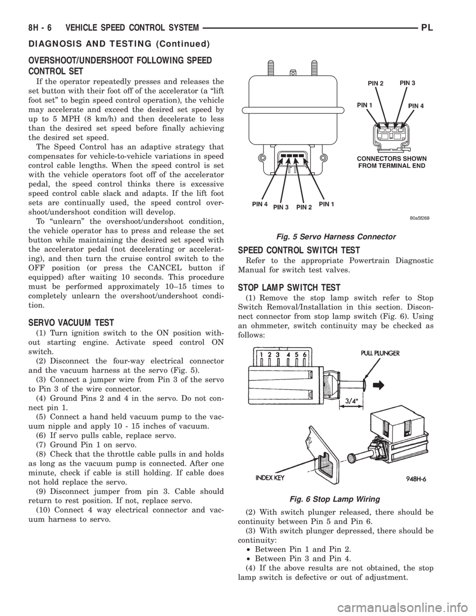
(2) Disconnect the four-way electrical connector
and the vacuum harness at the servo (Fig. 5).
(3) Connect a jumper wire from Pin 3 of the servo
to Pin 3 of the wire connector.
(4) Ground Pins 2 and 4 in the servo. Do not con-
nect pin 1.
(5) Connect a hand held vacuum pump to the vac-
uum nipple and apply 10 - 15 inches of vacuum.
(6) If servo pulls cable, replace servo.
(7) Ground Pin 1 on servo.
(8) Check that the throttle cable pulls in and holds
as long as the vacuum pump is connected. After one
minute, check if cable is still holding. If cable does
not hold replace the servo.
(9) Disconnect jumper from pin 3. Cable should
return to rest position. If not, replace servo.
(10) Connect 4 way electrical connector and vac-
uum harness to servo.
SPEED CONTROL SWITCH TEST
Refer to the appropriate Powertrain Diagnostic
Manual for switch test valves.
STOP LAMP SWITCH TEST
(1) Remove the stop lamp switch refer to Stop
Switch Removal/Installation in this section. Discon-
nect connector from stop lamp switch (Fig. 6). Using
an ohmmeter, switch continuity may be checked as
follows:
(2) With switch plunger released, there should be
continuity between Pin 5 and Pin 6.
(3) With switch plunger depressed, there should be
continuity:
²Between Pin 1 and Pin 2.
²Between Pin 3 and Pin 4.
(4) If the above results are not obtained, the stop
lamp switch is defective or out of adjustment.
Fig. 5 Servo Harness Connector
Fig. 6 Stop Lamp Wiring
8H - 6 VEHICLE SPEED CONTROL SYSTEMPL
DIAGNOSIS AND TESTING (Continued)