recommended oil DODGE NEON 1999 Service Repair Manual
[x] Cancel search | Manufacturer: DODGE, Model Year: 1999, Model line: NEON, Model: DODGE NEON 1999Pages: 1200, PDF Size: 35.29 MB
Page 4 of 1200
MAINTENANCE SCHEDULES
INDEX
page page
GENERAL INFORMATION
INTRODUCTION......................... 3
SCHEDULE ± A.......................... 3SCHEDULE ± B.......................... 4
UNSCHEDULED INSPECTION............... 3
GENERAL INFORMATION
INTRODUCTION
Service and maintenance procedures for compo-
nents and systems listed in Schedule ± A or B can be
found by using the Group Tab Locator index at the
front of this manual. If it is not clear which group
contains the information needed, refer to the index at
the back of this manual.
There are two maintenance schedules that show
proper service based on the conditions that the vehi-
cle is subjected to. Use the schedule that best
describes these conditions.
Schedule ±A, lists maintenance recommended for
vehicles used for general transportation.
Schedule ±B, lists maintenance recommended for
vehicles used under the following conditions:
²Frequent short trip driving less than 5 miles (8
km)
²Frequent driving in dusty conditions
²Frequent trailer towing
²Extensive idling
²More than 50% of your driving is at sustained
high speeds during hot weather, above 90ÉF (32ÉC)
Where time and mileage are listed, follow the
interval that occurs first.
EMISSION CONTROL SYSTEM MAINTENANCE
The scheduled emission maintenance listed inbold
typeon the Maintenance Schedules, must be done at
the mileage specified to assure the continued proper
functioning of the emission control system. These,
and all other maintenance services included in this
manual, should be done to provide the best vehicle
performance and reliability. More frequent mainte-
nance may be needed for vehicles in severe operating
conditions such as dusty areas and very short trip
driving.
UNSCHEDULED INSPECTION
At Each Stop For Fuel
²Check engine oil level, add as required.
²Check windshield washer solvent and add if
required.
Once A Month
²Check tire pressure and look for unusual wear
or damage.
²Inspect battery, clean, and tighten terminals as
required.
²Check fluid levels of coolant reservoir, power
steering and automatic transmission and add as
required.
²Check all lights and all other electrical items for
correct operation.
At Each Oil Change
²Inspect exhaust system.
²Inspect brake hoses.
²Inspect the CV joints and front suspension com-
ponents.
²Rotate the tires at each oil change interval
shown on Schedule ± A (7,500 miles) or every other
interval shown on schedule ± B (6,000 miles).
²Check coolant level, hoses and clamps.
²Check the manual transaxle fluid level.
²If the mileage is less than 7,500 miles (12 000
km) yearly, replace the engine oil filter at each oil
change.
SCHEDULE ± A
7,500 Miles (12 000 km) or at 6 months
²Change engine oil.
15,000 Miles (24 000 km) or at 12 months
²Change engine oil.
²Replace engine oil filter.
²Adjust drive belt tension.
22,500 Miles (36 000 km) or at 18 months
²Change engine oil.
²Inspect the front brake pads and rear brake lin-
ings.
30,000 Miles (48 000 km) or at 24 months
²Change engine oil.
²Replace engine oil filter.
²Lubricate front suspension ball joints.
²Adjust drive belt tension.
PLLUBRICATION AND MAINTENANCE 0 - 3
Page 7 of 1200
90,000 Miles (144 000 km)
²Change engine oil.
²Replace engine oil filter.
²Inspect front brake pads and rear brake linings.
²Check and replace, if necessary***, the PCV
valve.**
²Lubricate front suspension upper ball joints.
²Adjust drive belt tension.
²Replace air cleaner element.
²Replace spark plugs.
²Change automatic transaxle fluid and filter.
Adjust the bands.*
93,000 Miles (149 000 km)
²Change engine oil.
96,000 Miles (154 000 km)
²Change engine oil.
²Replace engine oil filter.
99,000 Miles (158 000 km)
²Change engine oil.
²Inspect front brake pads and rear brake linings.
102,000 Miles (163 000km)
²Change engine oil.
²Replace engine oil filter.
105,000 Miles (168 000km)
²Replace the engine timing belt
²Change engine oil.
²Replace engine oil filter.
²Adjust drive belt tension.
²Inspect and replace, if necessary, the air
cleaner element.
NOTE: **This maintenance is recommended by
Chrysler to the owner but is not required to main-
tain the warranty on the PCV valve.
NOTE: ***This maintenance is not required if the
PCV valve was previously replaced.
0 - 6 LUBRICATION AND MAINTENANCEPL
GENERAL INFORMATION (Continued)
Page 9 of 1200
DISCONNECT CABLE CLAMPS AS FOLLOWS:
²Disconnect BLACK cable clamp from engine
ground on disabled vehicle.
²When using a Booster vehicle, disconnect
BLACK cable clamp from battery negative terminal.
Disconnect RED cable clamp from battery positive
terminal.
²Disconnect RED cable clamp from battery posi-
tive terminal on disabled vehicle.
TOWING RECOMMENDATIONS
WARNING: DO NOT ALLOW TOWING ATTACH-
MENT DEVICES TO CONTACT THE FUEL TANK OR
LINES, FUEL LEAK CAN RESULT. DO NOT LIFT OR
TOW VEHICLE BY FRONT OR REAR BUMPER, OR
BUMPER ENERGY ABSORBER UNITS. DO NOT
VENTURE UNDER A LIFTED VEHICLE IF NOT SUP-
PORTED PROPERLY ON SAFETY STANDS. DO NOT
ALLOW PASSENGERS TO RIDE IN A TOWED VEHI-
CLE. USE A SAFETY CHAIN THAT IS INDEPENDENT
FROM THE TOWING ATTACHMENT DEVICE.
CAUTION: Do not damage brake lines, exhaust
system, shock absorbers, sway bars, or any other
under vehicle components when attaching towing
device to vehicle. Do not attach towing device to
front or rear suspension components. Do not
secure vehicle to towing device by the use of front
or rear suspension or steering components.
Remove or secure loose or protruding objects from
a damaged vehicle before towing. Refer to state and
local rules and regulations before towing a vehicle.
Do not allow weight of towed vehicle to bear on
lower fascia, air dams, or spoilers.
RECOMMENDED TOWING EQUIPMENT
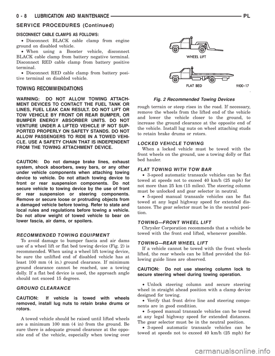
To avoid damage to bumper fascia and air dams
use of a wheel lift or flat bed towing device (Fig. 2) is
recommended. When using a wheel lift towing device,
be sure the unlifted end of disabled vehicle has at
least 100 mm (4 in.) ground clearance. If minimum
ground clearance cannot be reached, use a towing
dolly. If a flat bed device is used, the approach angle
should not exceed 15 degrees.
GROUND CLEARANCE
CAUTION: If vehicle is towed with wheels
removed, install lug nuts to retain brake drums or
rotors.
A towed vehicle should be raised until lifted wheels
are a minimum 100 mm (4 in) from the ground. Be
sure there is adequate ground clearance at the oppo-
site end of the vehicle, especially when towing overrough terrain or steep rises in the road. If necessary,
remove the wheels from the lifted end of the vehicle
and lower the vehicle closer to the ground, to
increase the ground clearance at the opposite end of
the vehicle. Install lug nuts on wheel attaching studs
to retain brake drums or rotors.
LOCKED VEHICLE TOWING
When a locked vehicle must be towed with the
front wheels on the ground, use a towing dolly or flat
bed hauler.
FLAT TOWING WITH TOW BAR
²3-speed automatic transaxle vehicles can be flat
towed at speeds not to exceed 40 km/h (25 mph) for
not more than 25 km (15 miles). The steering column
must be unlocked and gear selector in neutral.
²5-speed manual transaxle vehicles can be flat
towed at any legal highway speed for extended dis-
tances. The gear selector must be in the neutral posi-
tion.
TOWINGÐFRONT WHEEL LIFT
Chrysler Corporation recommends that a vehicle be
towed with the front end lifted, whenever possible.
TOWINGÐREAR WHEEL LIFT
If a vehicle cannot be towed with the front wheels
lifted, the rear wheels can be lifted provided the fol-
lowing guide lines are observed.
CAUTION: Do not use steering column lock to
secure steering wheel during towing operation.
²Unlock steering column and secure steering
wheel in straight ahead position with a clamp device
designed for towing.
²Verify that front drive line and steering compo-
nents are in good condition.
²5-speed manual transaxle vehicles can be towed
at any legal highway speed for extended distances.
The gear selector must be in the neutral position.
²3-speed automatic transaxle vehicles can be
towed at speeds not to exceed 40 km/h (25 mph) for
Fig. 2 Recommended Towing Devices
0 - 8 LUBRICATION AND MAINTENANCEPL
SERVICE PROCEDURES (Continued)
Page 148 of 1200
(3) Remove the rubber plug from the adjusting
hole in the brake shoe backing plate on both sides of
the vehicle.
(4)Driver (left) side park brake shoe adjust-
ment procedure.Insert a medium size screwdriver
through adjustment hole in backing plate. Position
the srewdriver against the starwheel on the park
brake shoe adjuster mechanism. Using the screw-
driver rotate the starwheeldownwarduntil a slight
drag is felt when turning the rear tire and wheel.
Then, using the screwdriver rotate the starwheel
upwardjust until the rear tire and wheel can be
rotated with no park brake shoe drag. From the
point where there is no more park brake drag rotate
the starwheelupwarda maximum of two additional
clicks. The park brake shoe to drum clearance is
know properly adjusted.
(5)Passenger (right) side park brake shoe
adjustment procedure.Insert a medium size
screwdriver through adjustment hole in backing
plate. Position the srewdriver against the starwheel
on the park brake shoe adjuster mechanism. Using
the screwdriver rotate the starwheelupwarduntil a
slight drag is felt when turning the rear tire and
wheel. Then, using the screwdriver rotate the star-
wheeldownwardjust until the rear tire and wheel
can be rotated with no park brake shoe drag. From
the point where there is no more park brake drag
rotate the starwheeldownwarda maximum of two
additional clicks. The park brake shoe to drum clear-
ance is know properly adjusted.
(6) Install the rubber plug in the adjusting hole on
the brake shoe backing plate on both sides of the
vehicle.
(7) Lower vehicle far enough to allow access the
park brake lever. The rear tires must not be on the
ground.
(8) Fully apply and release the park brakes two
times after adjusting the park brake shoes. Then
rotate both rear wheels to ensure that the park
brake shoes do not drag on the brake drum following
the application and release of the park brakes.
SPECIFICATIONS
BRAKE FLUID
The brake fluid used in this vehicle must conform
to DOT 3 specifications and SAE J1703 standards.
No other type of brake fluid is recommended or
approved for usage in the vehicle brake system. Use
only Mopar brake fluid or an equivalent from a
tightly sealed container.
CAUTION: Never use reclaimed brake fluid or fluid
from an container which has been left open. Anopen container will absorb moisture from the air
and contaminate the fluid.
CAUTION: Never use any type of a petroleum-
based fluid in the brake hydraulic system. Use of
such type fluids will result in seal damage of the
vehicle brake hydraulic system causing a failure of
the vehicle brake system. Petroleum based fluids
would be items such as engine oil, transmission
fluid, power steering fluid ect.
BRAKE ACTUATION SYSTEM
ACTUATION:
Vacuum Operated Power Brakes.........Standard
Hydraulic System...........Dual-Diagonally Split
MASTER CYLINDER ASSEMBLY:
Type ...........................Dual Tandem
Body Material...............Anodized Aluminum
Reservoir Material................Polypropelene
MASTER CYLINDER BORE / STROKE
AND SPLIT:
NonABS ....21mmx32.6 mm (.875 in. x 1.28 in.)
ABS........21mmx32.7 mm (.874 in. x 1.29 in.)
Displacement Split.....................50/50
MASTER CYLINDER FLUID OUTLET PORTS:
ABS ..........Primary 3/8±24 Secondary 7/16±24
Non ABS . . .Primary Inboard And Outboard 7/16±24
Non ABS . . .Secondary Inboard And Outboard 3/8±23
Outlet Fitting Type.......SAE 45 É Inverted Flare
ABS HYDRAULIC CONTROL UNIT:
Hydraulic Tube Fitting Type.SAE 45 É Inverted Flare
BOOSTER:
Make/Type.........Bendix Vacuum W/&W/O ABS
Mounting Studs.....................M8x1.25
Type ..........................230 mm Single
Boost At 20 inches Of Manifold Vacuum. . . .4690 All
PROPORTIONING VALVE:
Material...........................Aluminum
Function........Hydraulic Pressure Proportioning
BRAKE PEDAL
Pedal Ratio.............................3.28
BRAKE FASTENER TORQUE SPECIFICATIONS
DESCRIPTION TORQUE
BRAKE TUBES:
Tube Nuts To Fittings And
Components Except HCU. . . . 17 N´m (145 in. lbs.)
From Master Cylinder To
HCU At HCU Ports........21N´m(185 in. lbs.)
BRAKE HOSE:
To Caliper Banjo Bolt..........48N´m(35ft.lbs.)
Intermediate Bracket.........12N´m(105 in. lbs.)
PLBRAKES 5 - 67
ADJUSTMENTS (Continued)
Page 196 of 1200
ENGINE THERMOSTAT
The engine thermostat is located on the front of
the engine (radiator side) in the thermostat housing/
engine outlet connector. The thermostat has an air
bleed (vent) located in the flange and a O-ring for
sealing incorporate on it. There is a relief in the ther-
mostat housing/outlet connector for the O-ring.
WATER PUMP
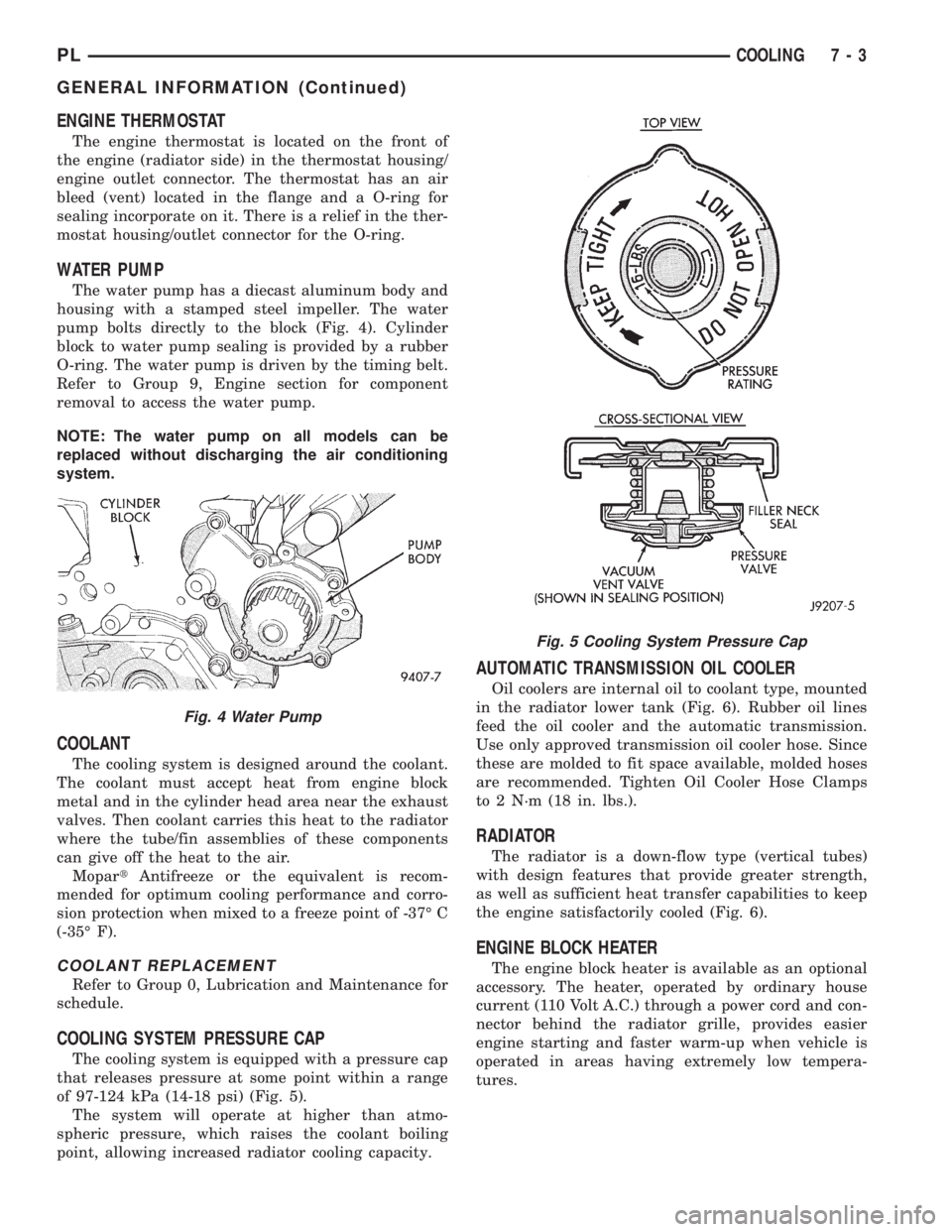
The water pump has a diecast aluminum body and
housing with a stamped steel impeller. The water
pump bolts directly to the block (Fig. 4). Cylinder
block to water pump sealing is provided by a rubber
O-ring. The water pump is driven by the timing belt.
Refer to Group 9, Engine section for component
removal to access the water pump.
NOTE: The water pump on all models can be
replaced without discharging the air conditioning
system.
COOLANT
The cooling system is designed around the coolant.
The coolant must accept heat from engine block
metal and in the cylinder head area near the exhaust
valves. Then coolant carries this heat to the radiator
where the tube/fin assemblies of these components
can give off the heat to the air.
MopartAntifreeze or the equivalent is recom-
mended for optimum cooling performance and corro-
sion protection when mixed to a freeze point of -37É C
(-35É F).
COOLANT REPLACEMENT
Refer to Group 0, Lubrication and Maintenance for
schedule.
COOLING SYSTEM PRESSURE CAP
The cooling system is equipped with a pressure cap
that releases pressure at some point within a range
of 97-124 kPa (14-18 psi) (Fig. 5).
The system will operate at higher than atmo-
spheric pressure, which raises the coolant boiling
point, allowing increased radiator cooling capacity.
AUTOMATIC TRANSMISSION OIL COOLER
Oil coolers are internal oil to coolant type, mounted
in the radiator lower tank (Fig. 6). Rubber oil lines
feed the oil cooler and the automatic transmission.
Use only approved transmission oil cooler hose. Since
these are molded to fit space available, molded hoses
are recommended. Tighten Oil Cooler Hose Clamps
to 2 N´m (18 in. lbs.).
RADIATOR
The radiator is a down-flow type (vertical tubes)
with design features that provide greater strength,
as well as sufficient heat transfer capabilities to keep
the engine satisfactorily cooled (Fig. 6).
ENGINE BLOCK HEATER
The engine block heater is available as an optional
accessory. The heater, operated by ordinary house
current (110 Volt A.C.) through a power cord and con-
nector behind the radiator grille, provides easier
engine starting and faster warm-up when vehicle is
operated in areas having extremely low tempera-
tures.
Fig. 4 Water Pump
Fig. 5 Cooling System Pressure Cap
PLCOOLING 7 - 3
GENERAL INFORMATION (Continued)
Page 198 of 1200
SELECTION AND ADDITIVES
The use of aluminum cylinder heads, intake mani-
folds DOHC, and water pumps requires special corro-
sion protection. MopartAntifreeze or the equivalent
is recommended for best engine cooling without cor-
rosion. When mixed only to a freeze point of -37ÉC
(-35ÉF) to -59ÉC (-50ÉF). If it looses color or becomes
contaminated, drain, flush, and replace with fresh
properly mixed solution.
COOLING SYSTEM PRESSURE CAP
The cooling system is equipped with a pressure cap
that releases built up pressure, maintaining a range
of 97-124 kPa (14-18 psi).
The cooling system will operate at higher than
atmospheric pressure. The higher pressure raises the
coolant boiling point thus, allowing increased radia-
tor cooling capacity.
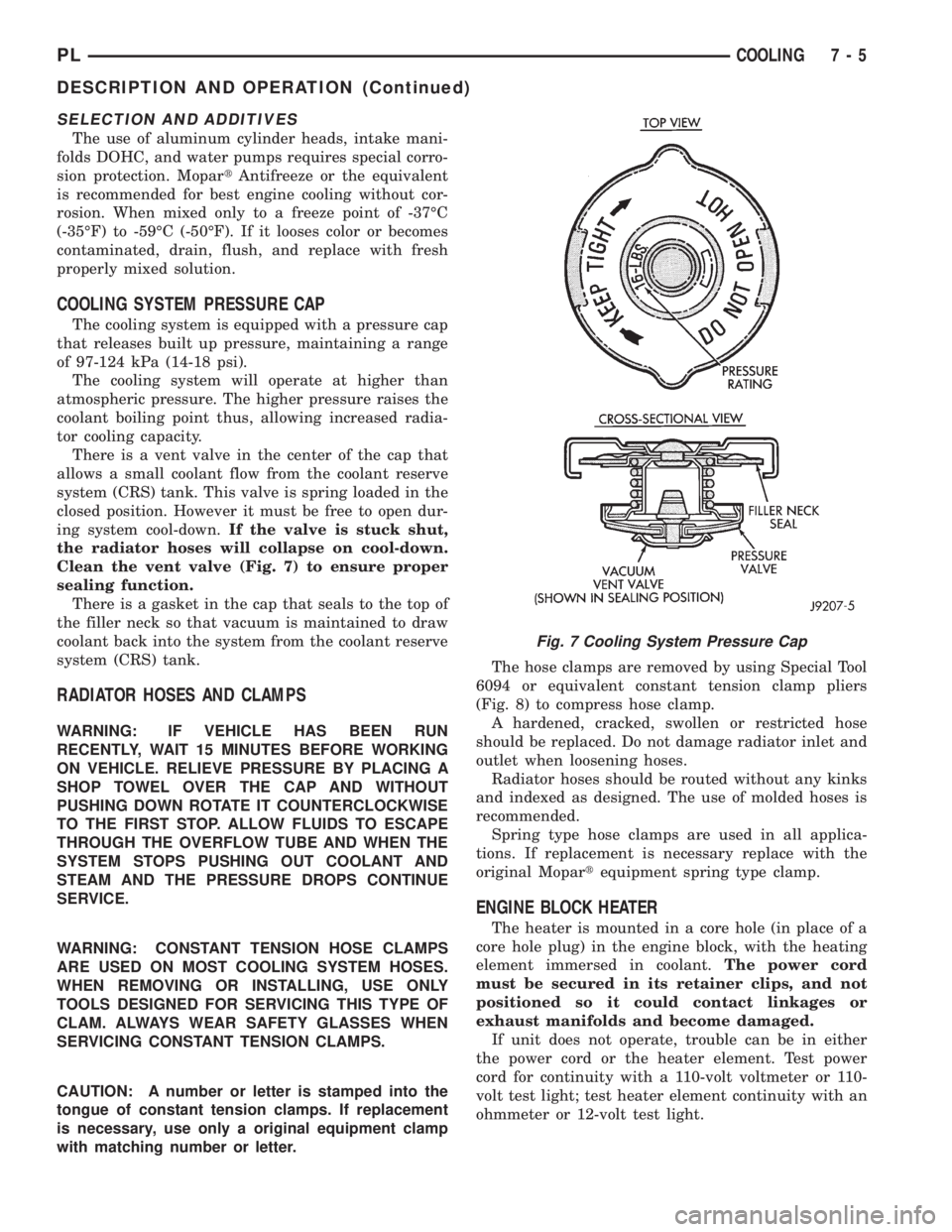
There is a vent valve in the center of the cap that
allows a small coolant flow from the coolant reserve
system (CRS) tank. This valve is spring loaded in the
closed position. However it must be free to open dur-
ing system cool-down.If the valve is stuck shut,
the radiator hoses will collapse on cool-down.
Clean the vent valve (Fig. 7) to ensure proper
sealing function.
There is a gasket in the cap that seals to the top of
the filler neck so that vacuum is maintained to draw
coolant back into the system from the coolant reserve
system (CRS) tank.
RADIATOR HOSES AND CLAMPS
WARNING: IF VEHICLE HAS BEEN RUN
RECENTLY, WAIT 15 MINUTES BEFORE WORKING
ON VEHICLE. RELIEVE PRESSURE BY PLACING A
SHOP TOWEL OVER THE CAP AND WITHOUT
PUSHING DOWN ROTATE IT COUNTERCLOCKWISE
TO THE FIRST STOP. ALLOW FLUIDS TO ESCAPE
THROUGH THE OVERFLOW TUBE AND WHEN THE
SYSTEM STOPS PUSHING OUT COOLANT AND
STEAM AND THE PRESSURE DROPS CONTINUE
SERVICE.
WARNING: CONSTANT TENSION HOSE CLAMPS
ARE USED ON MOST COOLING SYSTEM HOSES.
WHEN REMOVING OR INSTALLING, USE ONLY
TOOLS DESIGNED FOR SERVICING THIS TYPE OF
CLAM. ALWAYS WEAR SAFETY GLASSES WHEN
SERVICING CONSTANT TENSION CLAMPS.
CAUTION: A number or letter is stamped into the
tongue of constant tension clamps. If replacement
is necessary, use only a original equipment clamp
with matching number or letter.The hose clamps are removed by using Special Tool
6094 or equivalent constant tension clamp pliers
(Fig. 8) to compress hose clamp.
A hardened, cracked, swollen or restricted hose
should be replaced. Do not damage radiator inlet and
outlet when loosening hoses.
Radiator hoses should be routed without any kinks
and indexed as designed. The use of molded hoses is
recommended.
Spring type hose clamps are used in all applica-
tions. If replacement is necessary replace with the
original Mopartequipment spring type clamp.
ENGINE BLOCK HEATER
The heater is mounted in a core hole (in place of a
core hole plug) in the engine block, with the heating
element immersed in coolant.The power cord
must be secured in its retainer clips, and not
positioned so it could contact linkages or
exhaust manifolds and become damaged.
If unit does not operate, trouble can be in either
the power cord or the heater element. Test power
cord for continuity with a 110-volt voltmeter or 110-
volt test light; test heater element continuity with an
ohmmeter or 12-volt test light.
Fig. 7 Cooling System Pressure Cap
PLCOOLING 7 - 5
DESCRIPTION AND OPERATION (Continued)
Page 208 of 1200
There may be internal leaks, which can be deter-
mined by removing the oil dipstick. If water globules
appear intermixed with the oil, it indicates an inter-
nal leak in the engine. If there is an internal leak,
the engine must be disassembled for repair.
PRESSURE CAP TO FILLER NECK SEAL
PRESSURE RELIEF CHECK
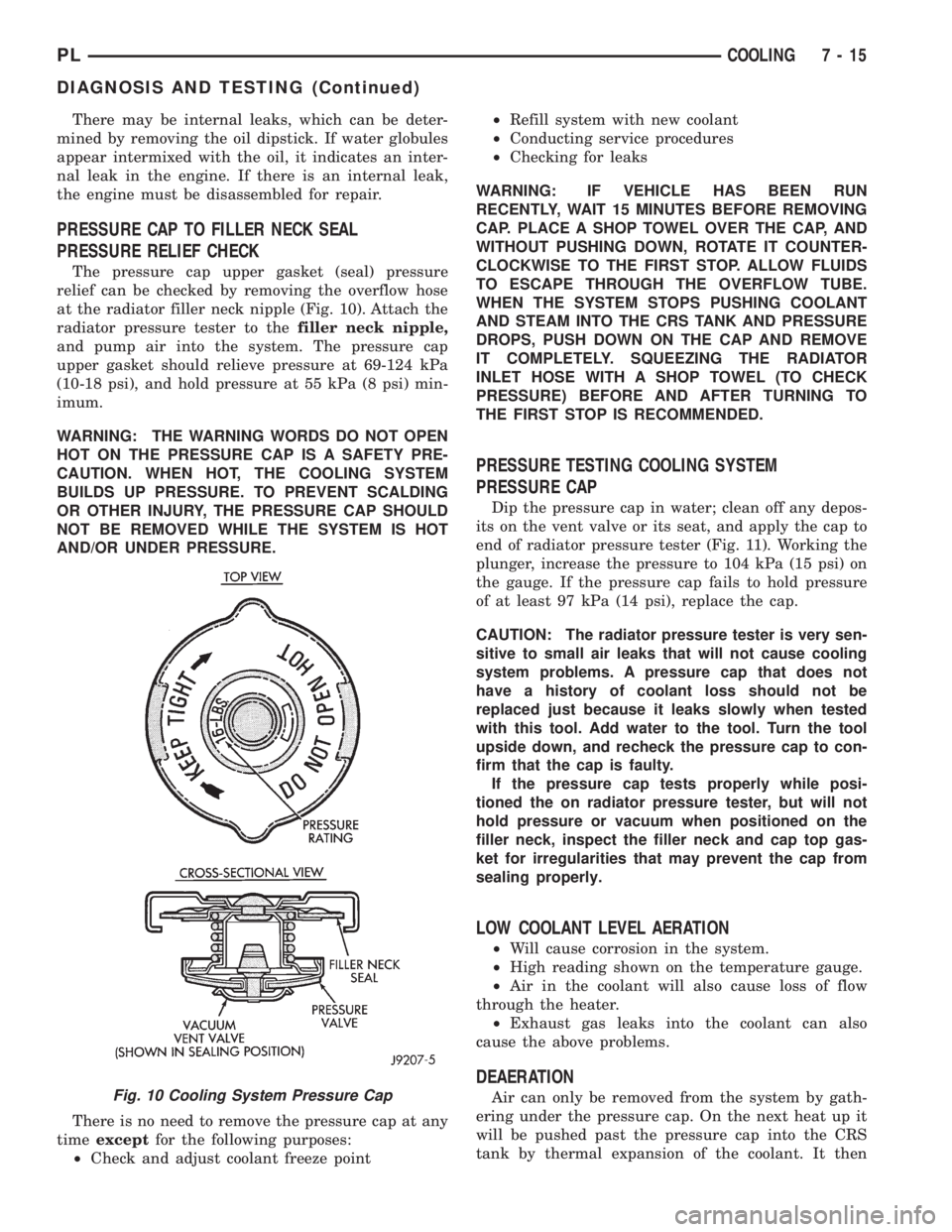
The pressure cap upper gasket (seal) pressure
relief can be checked by removing the overflow hose
at the radiator filler neck nipple (Fig. 10). Attach the
radiator pressure tester to thefiller neck nipple,
and pump air into the system. The pressure cap
upper gasket should relieve pressure at 69-124 kPa
(10-18 psi), and hold pressure at 55 kPa (8 psi) min-
imum.
WARNING: THE WARNING WORDS DO NOT OPEN
HOT ON THE PRESSURE CAP IS A SAFETY PRE-
CAUTION. WHEN HOT, THE COOLING SYSTEM
BUILDS UP PRESSURE. TO PREVENT SCALDING
OR OTHER INJURY, THE PRESSURE CAP SHOULD
NOT BE REMOVED WHILE THE SYSTEM IS HOT
AND/OR UNDER PRESSURE.
There is no need to remove the pressure cap at any
timeexceptfor the following purposes:
²Check and adjust coolant freeze point²Refill system with new coolant
²Conducting service procedures
²Checking for leaks
WARNING: IF VEHICLE HAS BEEN RUN
RECENTLY, WAIT 15 MINUTES BEFORE REMOVING
CAP. PLACE A SHOP TOWEL OVER THE CAP, AND
WITHOUT PUSHING DOWN, ROTATE IT COUNTER-
CLOCKWISE TO THE FIRST STOP. ALLOW FLUIDS
TO ESCAPE THROUGH THE OVERFLOW TUBE.
WHEN THE SYSTEM STOPS PUSHING COOLANT
AND STEAM INTO THE CRS TANK AND PRESSURE
DROPS, PUSH DOWN ON THE CAP AND REMOVE
IT COMPLETELY. SQUEEZING THE RADIATOR
INLET HOSE WITH A SHOP TOWEL (TO CHECK
PRESSURE) BEFORE AND AFTER TURNING TO
THE FIRST STOP IS RECOMMENDED.
PRESSURE TESTING COOLING SYSTEM
PRESSURE CAP
Dip the pressure cap in water; clean off any depos-
its on the vent valve or its seat, and apply the cap to
end of radiator pressure tester (Fig. 11). Working the
plunger, increase the pressure to 104 kPa (15 psi) on
the gauge. If the pressure cap fails to hold pressure
of at least 97 kPa (14 psi), replace the cap.
CAUTION: The radiator pressure tester is very sen-
sitive to small air leaks that will not cause cooling
system problems. A pressure cap that does not
have a history of coolant loss should not be
replaced just because it leaks slowly when tested
with this tool. Add water to the tool. Turn the tool
upside down, and recheck the pressure cap to con-
firm that the cap is faulty.
If the pressure cap tests properly while posi-
tioned the on radiator pressure tester, but will not
hold pressure or vacuum when positioned on the
filler neck, inspect the filler neck and cap top gas-
ket for irregularities that may prevent the cap from
sealing properly.
LOW COOLANT LEVEL AERATION
²Will cause corrosion in the system.
²High reading shown on the temperature gauge.
²Air in the coolant will also cause loss of flow
through the heater.
²Exhaust gas leaks into the coolant can also
cause the above problems.
DEAERATION
Air can only be removed from the system by gath-
ering under the pressure cap. On the next heat up it
will be pushed past the pressure cap into the CRS
tank by thermal expansion of the coolant. It thenFig. 10 Cooling System Pressure Cap
PLCOOLING 7 - 15
DIAGNOSIS AND TESTING (Continued)
Page 251 of 1200
The major difference between the two engines is
component location which affects the ignition system
service procedures. There are various sensors that
are in different locations due to a different cylinder
head and intake manifold.
The 2.0L engines use a fixed ignition timing sys-
tem. The distributorless electronic ignition system is
referred to as the Direct Ignition System (DIS).
Basic ignition timing is not adjustable.The
Powertrain Control Module (PCM) determines spark
advance. The system's three main components are
the coil pack, crankshaft position sensor, and cam-
shaft position sensor.
POWERTRAIN CONTROL MODULE
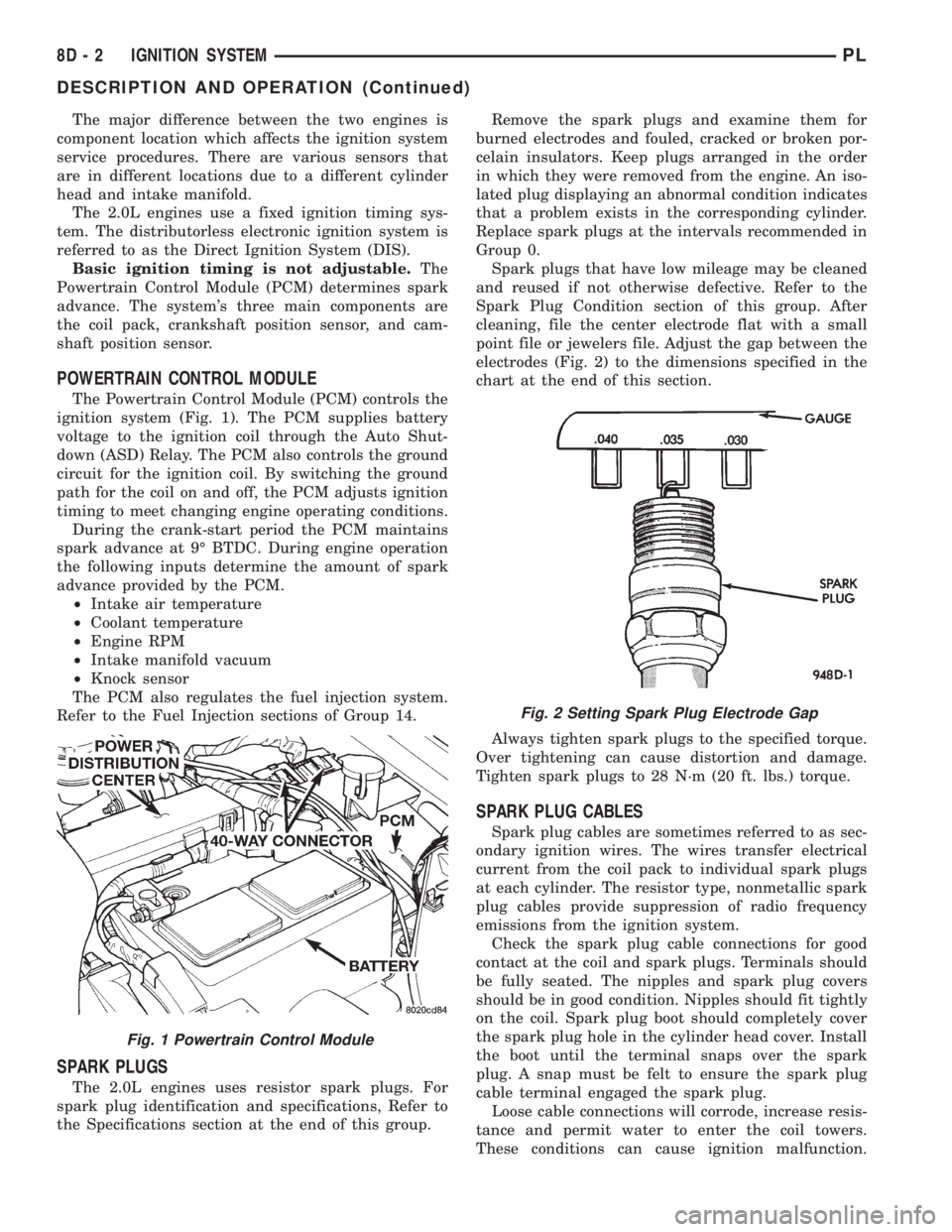
The Powertrain Control Module (PCM) controls the
ignition system (Fig. 1). The PCM supplies battery
voltage to the ignition coil through the Auto Shut-
down (ASD) Relay. The PCM also controls the ground
circuit for the ignition coil. By switching the ground
path for the coil on and off, the PCM adjusts ignition
timing to meet changing engine operating conditions.
During the crank-start period the PCM maintains
spark advance at 9É BTDC. During engine operation
the following inputs determine the amount of spark
advance provided by the PCM.
²Intake air temperature
²Coolant temperature
²Engine RPM
²Intake manifold vacuum
²Knock sensor
The PCM also regulates the fuel injection system.
Refer to the Fuel Injection sections of Group 14.
SPARK PLUGS
The 2.0L engines uses resistor spark plugs. For
spark plug identification and specifications, Refer to
the Specifications section at the end of this group.Remove the spark plugs and examine them for
burned electrodes and fouled, cracked or broken por-
celain insulators. Keep plugs arranged in the order
in which they were removed from the engine. An iso-
lated plug displaying an abnormal condition indicates
that a problem exists in the corresponding cylinder.
Replace spark plugs at the intervals recommended in
Group 0.
Spark plugs that have low mileage may be cleaned
and reused if not otherwise defective. Refer to the
Spark Plug Condition section of this group. After
cleaning, file the center electrode flat with a small
point file or jewelers file. Adjust the gap between the
electrodes (Fig. 2) to the dimensions specified in the
chart at the end of this section.
Always tighten spark plugs to the specified torque.
Over tightening can cause distortion and damage.
Tighten spark plugs to 28 N´m (20 ft. lbs.) torque.
SPARK PLUG CABLES
Spark plug cables are sometimes referred to as sec-
ondary ignition wires. The wires transfer electrical
current from the coil pack to individual spark plugs
at each cylinder. The resistor type, nonmetallic spark
plug cables provide suppression of radio frequency
emissions from the ignition system.
Check the spark plug cable connections for good
contact at the coil and spark plugs. Terminals should
be fully seated. The nipples and spark plug covers
should be in good condition. Nipples should fit tightly
on the coil. Spark plug boot should completely cover
the spark plug hole in the cylinder head cover. Install
the boot until the terminal snaps over the spark
plug. A snap must be felt to ensure the spark plug
cable terminal engaged the spark plug.
Loose cable connections will corrode, increase resis-
tance and permit water to enter the coil towers.
These conditions can cause ignition malfunction.
Fig. 1 Powertrain Control Module
Fig. 2 Setting Spark Plug Electrode Gap
8D - 2 IGNITION SYSTEMPL
DESCRIPTION AND OPERATION (Continued)
Page 715 of 1200
assure gasket rails are flat. Flatten rails with a ham-
mer on a heavy steel plate if required. Gasket sur-
faces must be free of oil and dirt. Make sure old
gasket material is removed from blind attaching
holes.
FORM-IN-PLACE GASKET APPLICATION
Assembling parts using a form-in-place gasket
requires care but it's easier then using precut gas-
kets.
MopartGasket Maker material should be applied
sparingly 1 mm (0.040 inch.) diameter or less of seal-
ant to one gasket surface. Be certain the material
surrounds each mounting hole. Excess material can
easily be wiped off. Components should be torqued in
place within 15 minutes. The use of a locating dowel
is recommended during assembly to prevent smear-
ing material off the location.
The MopartSilicone Rubber Adhesive Sealant gas-
ket material or equivalent should be applied in a con-
tinuous bead approximately 3 mm (0.120 inch) in
diameter. All mounting holes must be circled. For
corner sealing, a 3.17 or 6.35 mm (1/8 or 1/4 inch.)
drop is placed in the center of the gasket contact
area. Uncured sealant may be removed with a shop
towel. Components should be torqued in place while
the sealant is still wet to the touch (within 10 min-
utes). The usage of a locating dowel is recommended
during assembly to prevent smearing material off the
location.
CRANKSHAFT SPROCKET BOLT ACCESS PLUG
An Access plug is located in the right inner fender
shield. Remove the plug and insert the proper size
socket, extension and ratchet, when crankshaft rota-
tion is necessary.
ENGINE CORE PLUGS
REMOVAL
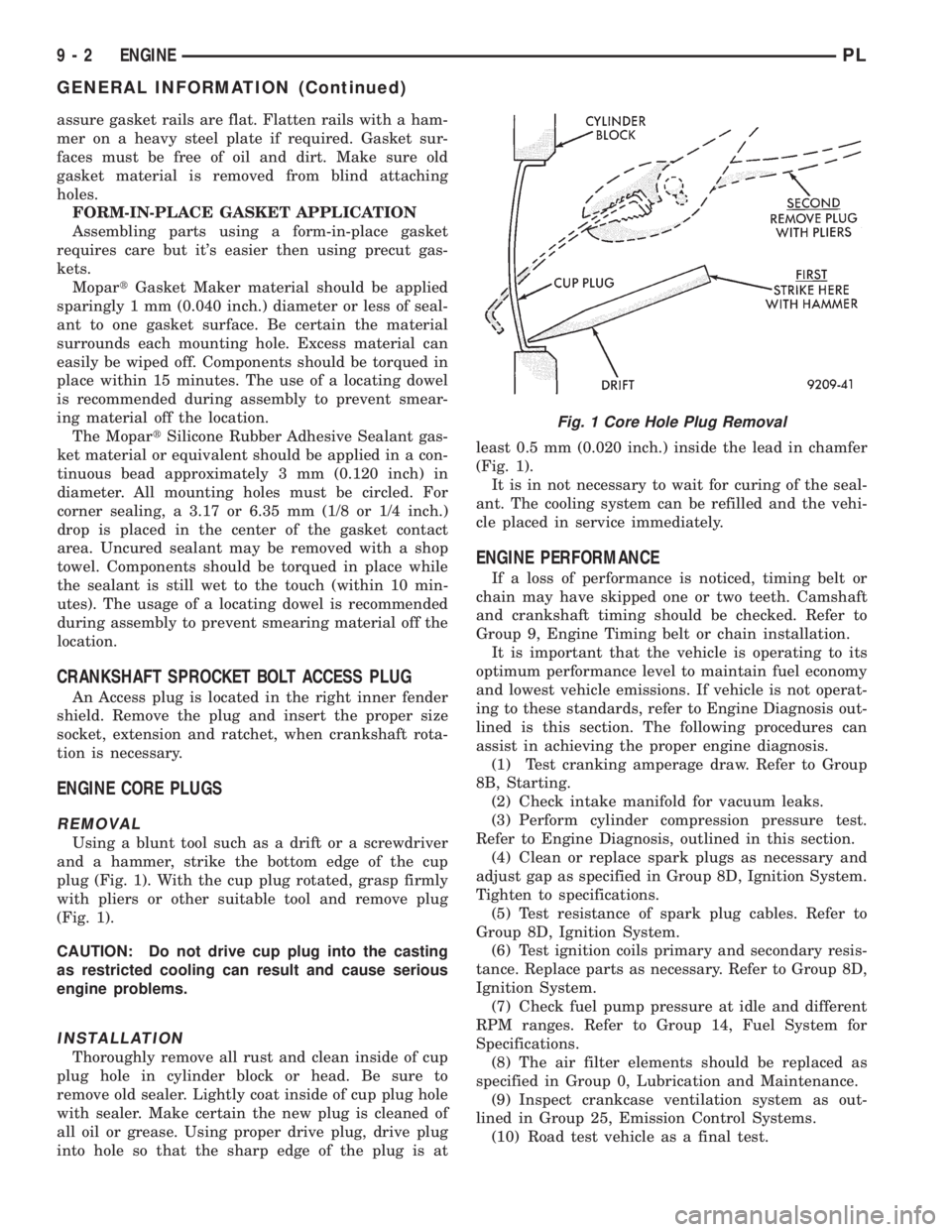
Using a blunt tool such as a drift or a screwdriver
and a hammer, strike the bottom edge of the cup
plug (Fig. 1). With the cup plug rotated, grasp firmly
with pliers or other suitable tool and remove plug
(Fig. 1).
CAUTION: Do not drive cup plug into the casting
as restricted cooling can result and cause serious
engine problems.
INSTALLATION
Thoroughly remove all rust and clean inside of cup
plug hole in cylinder block or head. Be sure to
remove old sealer. Lightly coat inside of cup plug hole
with sealer. Make certain the new plug is cleaned of
all oil or grease. Using proper drive plug, drive plug
into hole so that the sharp edge of the plug is atleast 0.5 mm (0.020 inch.) inside the lead in chamfer
(Fig. 1).
It is in not necessary to wait for curing of the seal-
ant. The cooling system can be refilled and the vehi-
cle placed in service immediately.
ENGINE PERFORMANCE
If a loss of performance is noticed, timing belt or
chain may have skipped one or two teeth. Camshaft
and crankshaft timing should be checked. Refer to
Group 9, Engine Timing belt or chain installation.
It is important that the vehicle is operating to its
optimum performance level to maintain fuel economy
and lowest vehicle emissions. If vehicle is not operat-
ing to these standards, refer to Engine Diagnosis out-
lined is this section. The following procedures can
assist in achieving the proper engine diagnosis.
(1) Test cranking amperage draw. Refer to Group
8B, Starting.
(2) Check intake manifold for vacuum leaks.
(3) Perform cylinder compression pressure test.
Refer to Engine Diagnosis, outlined in this section.
(4) Clean or replace spark plugs as necessary and
adjust gap as specified in Group 8D, Ignition System.
Tighten to specifications.
(5) Test resistance of spark plug cables. Refer to
Group 8D, Ignition System.
(6) Test ignition coils primary and secondary resis-
tance. Replace parts as necessary. Refer to Group 8D,
Ignition System.
(7) Check fuel pump pressure at idle and different
RPM ranges. Refer to Group 14, Fuel System for
Specifications.
(8) The air filter elements should be replaced as
specified in Group 0, Lubrication and Maintenance.
(9) Inspect crankcase ventilation system as out-
lined in Group 25, Emission Control Systems.
(10) Road test vehicle as a final test.
Fig. 1 Core Hole Plug Removal
9 - 2 ENGINEPL
GENERAL INFORMATION (Continued)
Page 716 of 1200
HONING CYLINDER BORES
(1) Used carefully, the cylinder bore resizing hone
C-823 equipped with 220 grit stones, is the best tool
for this job. In addition to deglazing, it will reduce
taper and out-of-round as well as removing light
scuffing, scoring or scratches. Usually a few strokes
will clean up a bore and maintain the required lim-
its.
(2) Deglazing of the cylinder walls may be done
using a cylinder surfacing hone, Tool C-3501,
equipped with 280 grit stones, if the cylinder bore is
straight and round. 20-60 strokes depending on the
bore condition, will be sufficient to provide a satisfac-
tory surface. Inspect cylinder walls after each 20
strokes, using a light honing oil.Do not use engine
or transmission oil, mineral spirits or kerosene.
(3) Honing should be done by moving the hone up
and down fast enough to get a cross-hatch pattern.
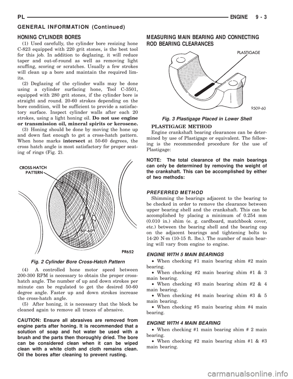
When hone marksintersectat 50-60 degrees, the
cross hatch angle is most satisfactory for proper seat-
ing of rings (Fig. 2).
(4) A controlled hone motor speed between
200-300 RPM is necessary to obtain the proper cross-
hatch angle. The number of up and down strokes per
minute can be regulated to get the desired 50-60
degree angle. Faster up and down strokes increase
the cross-hatch angle.
(5) After honing, it is necessary that the block be
cleaned again to remove all traces of abrasive.
CAUTION: Ensure all abrasives are removed from
engine parts after honing. It is recommended that a
solution of soap and hot water be used with a
brush and the parts then thoroughly dried. The bore
can be considered clean when it can be wiped
clean with a white cloth and cloth remains clean.
Oil the bores after cleaning to prevent rusting.
MEASURING MAIN BEARING AND CONNECTING
ROD BEARING CLEARANCES
PLASTIGAGE METHOD
Engine crankshaft bearing clearances can be deter-
mined by use of Plastigage or equivalent. The follow-
ing is the recommended procedure for the use of
Plastigage:
NOTE: The total clearance of the main bearings
can only be determined by removing the weight of
the crankshaft. This can be accomplished by either
of two methods:
PREFERRED METHOD
Shimming the bearings adjacent to the bearing to
be checked in order to remove the clearance between
upper bearing shell and the crankshaft. This can be
accomplished by placing a minimum of 0.254 mm
(0.010 in.) shim (e. g. cardboard, matchbook cover,
etc.) between the bearing shell and the bearing cap
on the adjacent bearings and tightening bolts to
14-20 N´m (10-15 ft. lbs.). The number of main bear-
ing will vary from engine to engine.
ENGINE WITH 5 MAIN BEARINGS
²When checking #1 main bearing shim #2 main
bearing.
²When checking #2 main bearing shim #1 & 3
main bearing.
²When checking #3 main bearing shim #2 & 4
main bearing.
²When checking #4 main bearing shim #3 & 5
main bearing.
²When checking #5 main bearing shim #4 main
bearing.
ENGINE WITH 4 MAIN BEARING
²When checking #1 main bearing shim # 2 main
bearing.
²When checking #2 main bearing shim #1 & #3
main bearing.
Fig. 2 Cylinder Bore Cross-Hatch Pattern
Fig. 3 Plastigage Placed in Lower Shell
PLENGINE 9 - 3
GENERAL INFORMATION (Continued)