oil reset DODGE NEON 1999 Service Repair Manual
[x] Cancel search | Manufacturer: DODGE, Model Year: 1999, Model line: NEON, Model: DODGE NEON 1999Pages: 1200, PDF Size: 35.29 MB
Page 55 of 1200

(7) Remove carpet (if required) from top of strut
tower. Then remove rubber dust shield (Fig. 8) from
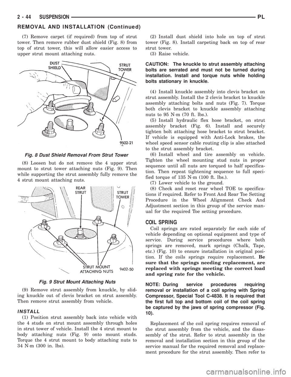
top of strut tower, this will allow easier access to
upper strut mount attaching nuts.
(8) Loosen but do not remove the 4 upper strut
mount to strut tower attaching nuts (Fig. 9). Then
while supporting the strut assembly fully remove the
4 strut mount attaching nuts.
(9) Remove strut assembly from knuckle, by slid-
ing knuckle out of clevis bracket on strut assembly.
Then remove strut assembly from vehicle.
INSTALL
(1) Position strut assembly back into vehicle with
the 4 studs on strut mount assembly through holes
in strut tower of vehicle. Install the 4 strut mount to
body attaching nuts (Fig. 9) onto mount studs.
Torque the 4 strut mount to body attaching nuts to
34 N´m (300 in. lbs).(2) Install dust shield into hole on top of strut
tower (Fig. 8). Install carpeting back on top of rear
strut tower.
(3) Raise vehicle.
CAUTION: The knuckle to strut assembly attaching
bolts are serrated and must not be turned during
installation. Install and torque nuts while holding
bolts stationary in knuckle.
(4) Install knuckle assembly into clevis bracket on
strut assembly. Install the 2 clevis bracket to knuckle
assembly attaching bolts and nuts (Fig. 7). Torque
both clevis bracket to knuckle assembly attaching
nuts to 95 N´m (70 ft. lbs.).
(5) Install hydraulic flex hose bracket, on strut
assembly bracket (Fig. 6). Install and securely
tighten bolt attaching hose bracket to strut bracket.
If vehicle is equipped with Anti-Lock brakes, the
wheel speed sensor cable routing clip is also attached
to the strut assembly bracket.
(6) Install wheel and tire assembly on vehicle.
Tighten the wheel mounting stud nuts in proper
sequence until all nuts are torqued to half specifica-
tion. Then repeat tightening sequence to full speci-
fied torque of 135 N´m (100 ft. lbs.).
(7) Lower vehicle to the ground.
(8) Check and reset rear wheel TOE to specifica-
tions if required. Refer to Front And Rear Toe Setting
Procedure in the Wheel Alignment Check And
Adjustment section in this group of the service man-
ual for the required Toe setting procedure.
COIL SPRING
Coil springs are rated separately for each side of
vehicle depending on optional equipment and type of
service. During service procedures where both
springs are removed, mark springs (Chalk, Tape,
etc.) (Fig. 10) to ensure installation in original posi-
tion. If the coils springs require replacement.Be
sure that the springs needing replacement, are
replaced with springs meeting the correct load
and spring rate for the vehicle.
NOTE: During service procedures requiring
removal or installation of a coil spring with Spring
Compressor, Special Tool C-4838. It is required that
the first full top and bottom coil of the coil spring
be captured by the jaws of spring compressor (Fig.
10).
Replacement of the coil spring requires removal of
the strut assembly from the vehicle, and the disas-
sembly of the strut. Refer to strut assembly in the
removal and installation section in this group of the
service manual for the required removal and replace-
ment procedure for the strut assembly. Then refer to
Fig. 8 Dust Shield Removal From Strut Tower
Fig. 9 Strut Mount Attaching Nuts
2 - 44 SUSPENSIONPL
REMOVAL AND INSTALLATION (Continued)
Page 61 of 1200

link mounting bolt at crossmember MUST be
installed, with head of bolt facing rear of vehi-
cle. The long attaching bolt must be used at
rear crossmember and short bolt used at
knuckle.
(1) Install washer on short lateral link attaching
bolt. Then install short lateral link attaching bolt,
into lateral link having the same size bushing
sleeves. Then install lateral link, bolt and washer
onto knuckle as an assembly, with head of bolt facing
to front of vehicle (Fig. 24).
(2) Install lateral link with small and large bush-
ing sleeve, on lateral link attaching bolt in rear
knuckle (Fig. 24).Small bushing sleeve must be
installed on bolt in rear knuckle with large
bushing sleeve at crossmember of vehicle.
(3) Install washer and nut onto lateral link attach-
ing bolt at rear knuckle (Fig. 24).Do not tighten
the lateral link to rear knuckle attaching bolt
at this time.
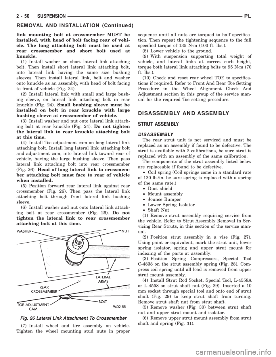
(4) Install Toe adjustment cam on long lateral link
attaching bolt. Install long lateral link attaching bolt
and adjustment cam, into lateral link toward rear of
vehicle, having the large bushing sleeve. Then pass
lateral link attaching bolt into rear crossmember
(Fig. 26).Head of long lateral link to crossmem-
ber attaching bolt must face to rear of vehicle
when installed.
(5) Position forward rear lateral link against rear
crossmember (Fig. 26). Then pass the lateral link
attaching bolt through front lateral link bushing
sleeve.
(6) Install washer and nut onto lateral link attach-
ing bolt at rear crossmember (Fig. 26).Do not
tighten the lateral link to rear crossmember
attaching bolt at this time.
(7) Install wheel and tire assembly on vehicle.
Tighten the wheel mounting stud nuts in propersequence until all nuts are torqued to half specifica-
tion. Then repeat the tightening sequence to the full
specified torque of 135 N´m (100 ft. lbs.).
(8) Lower vehicle to the ground.
(9) With suspension supporting total weight of
vehicle, and lateral links at correct curb height,
torque both lateral link attaching bolts to 95 N´m (70
ft. lbs.).
(10) Check and reset rear wheel TOE to specifica-
tions if required. Refer to Front And Rear Toe Setting
Procedure in the Wheel Alignment Check And
Adjustment section in this group of the service man-
ual for the required Toe setting procedure.
DISASSEMBLY AND ASSEMBLY
STRUT ASSEMBLY
DISASSEMBLY
The rear strut unit is not serviced and must be
replaced as an assembly if found to be defective. The
strut is available with 2 calibrations, be sure strut is
replaced with an assembly of the same calibration.
The components of the strut assembly listed below
are replaceable if found to be defective.
²Coil spring (Coil springs come in a standard rate
of 120 lb./in. be sure spring is replaced with a spring
of the same rate.)
²Dust shield
²Mount assembly
²Jounce Bumper
²Lower Spring Isolator
²Shaft Nut
(1) Remove strut assembly requiring service from
the vehicle. Refer to Strut Assembly Removal in Ser-
vicing Rear Struts, in this section of the service man-
ual.
(2) Position strut assembly in a vise (Fig. 27).
Using paint or equivalent, mark the strut unit, lower
spring isolator, spring and upper strut mount for
indexing of the parts at assembly.
(3) Position Spring Compressors, Special Tool
C-4838 on the strut assembly spring (Fig. 28). Com-
press coil spring until all load is removed from upper
strut mount assembly.
(4) Install Strut Rod Socket, Special Tool, L-4558A
or L-4558 on strut shaft nut (Fig. 29). Inserted a 10
mm socket through special tool and onto end of strut
shaft (Fig. 29) to keep strut shaft from turning.
Remove strut shaft nut from strut shaft.
(5) Remove washer (Fig. 30) between strut shaft
nut and upper strut mount and isolator.
(6) Remove upper strut mount assembly from strut
shaft and spring (Fig. 31).
Fig. 26 Lateral Link Attachment To Crossmember
2 - 50 SUSPENSIONPL
REMOVAL AND INSTALLATION (Continued)
Page 862 of 1200

GENERAL INFORMATION
INTRODUCTION
All engines used in this section have a sequential
Multi-Port Electronic Fuel Injection system. The MPI
system is computer regulated and provides precise
air/fuel ratios for all driving conditions. The Power-
train Control Module (PCM) operates the fuel injec-
tion system.
The PCM regulates:
²Ignition timing
²Air/fuel ratio
²Emission control devices
²Cooling fan
²Charging system
²Idle speed
²Vehicle speed control
Various sensors provide the inputs necessary for
the PCM to correctly operate these systems. In addi-
tion to the sensors, various switches also provide
inputs to the PCM.
All inputs to the PCM are converted into signals.
The PCM can adapt its programming to meet chang-
ing operating conditions.
Fuel is injected into the intake port above the
intake valve in precise metered amounts through
electrically operated injectors. The PCM fires the
injectors in a specific sequence. Under most operat-
ing conditions, the PCM maintains an air fuel ratio
of 14.7 parts air to 1 part fuel by constantly adjust-
ing injector pulse width. Injector pulse width is the
length of time the injector is open.
The PCM adjusts injector pulse width by opening
and closing the ground path to the injector. Engine
RPM (speed) and manifold absolute pressure (air
density) are the primary inputs that determine injec-
tor pulse width.
MODES OF OPERATION
As input signals to the PCM change, the PCM
adjusts its response to output devices. For example,
the PCM must calculate a different injector pulse
width and ignition timing for idle than it does for
Wide Open Throttle (WOT). There are several differ-
ent modes of operation that determine how the PCM
responds to the various input signals.
There are two different areas of operation, OPEN
LOOP and CLOSED LOOP.
During OPEN LOOP modes the PCM receives
input signals and responds according to preset PCM
programming. Inputs from the upstream and down-
stream heated oxygen sensors are not monitored dur-
ing OPEN LOOP modes, except for heated oxygen
sensor diagnostics (they are checked for shorted con-
ditions at all times).During CLOSED LOOP modes the PCM monitors
the inputs from the upstream and downstream
heated oxygen sensors. The upstream heated oxygen
sensor input tells the PCM if the calculated injector
pulse width resulted in the ideal air-fuel ratio of 14.7
to one. By monitoring the exhaust oxygen content
through the upstream heated oxygen sensor, the
PCM can fine tune injector pulse width. Fine tuning
injector pulse width allows the PCM to achieve opti-
mum fuel economy combined with low emissions.
For the PCM to enter CLOSED LOOP operation,
the following must occur:
(1) Engine coolant temperature must be over 35ÉF.
²If the coolant is over 35É the PCM will wait 44
seconds.
²If the coolant is over 50ÉF the PCM will wait 38
seconds.
²If the coolant is over 167ÉF the PCM will wait
11 seconds.
(2) For other temperatures the PCM will interpo-
late the correct waiting time.
(3) O2 sensor must read either greater than .745
volts or less than .1 volt.
(4) The multi-port fuel injection systems has the
following modes of operation:
²Ignition switch ON (Zero RPM)
²Engine start-up
²Engine warm-up
²Cruise
²Idle
²Acceleration
²Deceleration
²Wide Open Throttle
²Ignition switch OFF
(5) The engine start-up (crank), engine warm-up,
deceleration with fuel shutoff and wide open throttle
modes are OPEN LOOP modes. Under most operat-
ing conditions, the acceleration, deceleration (with
A/C on), idle and cruise modes,with the engine at
operating temperatureare CLOSED LOOP modes.
IGNITION SWITCH ON (ZERO RPM) MODE
When the ignition switch activates the fuel injec-
tion system, the following actions occur:
²The PCM monitors the engine coolant tempera-
ture sensor and throttle position sensor input. The
PCM determines basic fuel injector pulse width from
this input.
²The PCM determines atmospheric air pressure
from the MAP sensor input to modify injector pulse
width.
When the key is in the ON position and the engine
is not running (zero rpm), the Auto Shutdown (ASD)
and fuel pump relays de-energize after approximately
1 second. Therefore, battery voltage is not supplied to
the fuel pump, ignition coil, fuel injectors and heated
oxygen sensors.
PLFUEL SYSTEM 14 - 21