oil temperature DODGE NEON 1999 Service Repair Manual
[x] Cancel search | Manufacturer: DODGE, Model Year: 1999, Model line: NEON, Model: DODGE NEON 1999Pages: 1200, PDF Size: 35.29 MB
Page 194 of 1200
COOLING
CONTENTS
page page
GENERAL INFORMATION
ACCESSORY DRIVE BELTS................ 2
AUTOMATIC TRANSMISSION OIL COOLER.... 3
COOLANT RECOVERY SYSTEM (CRS)....... 2
COOLANT.............................. 3
COOLING SYSTEM PRESSURE CAP......... 3
COOLING SYSTEM....................... 1
ENGINE BLOCK HEATER.................. 3
ENGINE THERMOSTAT.................... 3
RADIATOR............................. 3
WATER PUMP.......................... 3
DESCRIPTION AND OPERATION
COOLANT PERFORMANCE................. 4
COOLING SYSTEM PRESSURE CAP......... 5
ENGINE BLOCK HEATER.................. 5
ENGINE THERMOSTAT.................... 4
RADIATOR HOSES AND CLAMPS........... 5
WATER PUMP.......................... 6
DIAGNOSIS AND TESTING
ACCESSORY DRIVEBELT DIAGNOSIS....... 13
COOLING SYSTEM DIAGNOSIS............. 7
COOLING SYSTEM FLOW CHECK.......... 14
DEAERATION.......................... 15
ELECTRIC FAN MOTOR TEST.............. 14
ENGINE THERMOSTAT TESTING........... 13
LOW COOLANT LEVEL AERATION.......... 15
PRESSURE CAP TO FILLER NECK SEAL
PRESSURE RELIEF CHECK.............. 15
PRESSURE TESTING COOLING SYSTEM
PRESSURE CAP...................... 15
RADIATOR FAN CONTROL................ 14
TEMPERATURE GAUGE INDICATION........ 16
TESTING COOLING SYSTEM FOR LEAKS.... 14WATER PUMP DIAGNOSIS............... 14
SERVICE PROCEDURES
COOLANT LEVEL CHECKÐROUTINE........ 16
COOLANT LEVELÐSERVICING............ 16
COOLANTÐADDING ADDITIONAL......... 16
COOLING SYSTEMÐDRAINING............ 16
COOLING SYSTEMÐREFILLING........... 17
REMOVAL AND INSTALLATION
ACCESSORY DRIVE BELTS............... 21
ENGINE BLOCK HEATER................. 21
ENGINE THERMOSTAT................... 18
RADIATOR DRAINCOCK.................. 20
RADIATOR FANS AND MOTOR............ 20
RADIATOR............................ 19
WATER PUMP INLET TUBE............... 18
WATER PUMP......................... 17
CLEANING AND INSPECTION
ACCESSORY DRIVE BELT INSPECTION...... 22
CHEMICAL CLEANING................... 23
CLEANING COOLING SYSTEM............. 22
COOLING SYSTEM CAP.................. 22
RADIATOR FLUSHING................... 23
REVERSE FLUSHING.................... 23
WATER PUMP......................... 21
ADJUSTMENTS
BELT TENSION GAUGE METHOD........... 24
PROPER BELT TENSION................. 23
SPECIFICATIONS
COOLING SYSTEM CAPACITY............. 24
TORQUE.............................. 24
SPECIAL TOOLS
COOLING............................. 24
GENERAL INFORMATION
COOLING SYSTEM
The cooling system consists of an engine cooling
module, thermostat, coolant, and a water pump to
circulate the coolant. The engine cooling module may
consist of a radiator, electric fan motor, fan, shroud,
coolant reserve system, transmission oil cooler, hoses,
clamps, air condition condenser and transmission oil lines.
²When the Engine is cold: The thermostat is
closed; the cooling system has no flow through the
radiator. The coolant flows through the engine,
heater system and bypass.
²When the Engine is warm: Thermostat is open;
the cooling system has flow through radiator, engine,
heater system and bypass.
Coolant flow circuit for the 2.0L engine is shown in
(Fig. 1).
PLCOOLING 7 - 1
Page 197 of 1200
DESCRIPTION AND OPERATION
ENGINE THERMOSTAT
The engine cooling thermostats are wax pellet
driven, reverse poppet choke type. They are designed
to provide the fastest warm up possible by prevent-
ing leakage through them and to guarantee a mini-
mum engine operating temperature of 88 to 93ÉC
(192 to 199ÉF). They also automatically reach wide
open so they do not restrict flow to the radiator as
temperature of the coolant rises in hot weather to
around 104ÉC (220ÉF). Above this temperature the
coolant temperature is controlled by the radiator, fan,
and ambient temperature, not the thermostat.
Its primary purpose is to maintain engine temper-
ature in a range that will provide satisfactory engine
performance and emission levels under all expected
driving conditions. It also provides hot water (cool-
ant) for heater performance. It does this by transfer-
ring heat from engine metal and automatic
transmission oil cooler (if equipped) to coolant, mov-
ing this heated coolant to the heater core and radia-
tor, and then transferring this heat to the ambient
air.
COOLANT PERFORMANCE
Performance is measurable. For heat transfer pure
water excels (Formula = 1 btu per minute for each
degree of temperature rise for each pound of water).
This formula is altered when necessary additives to
control boiling, freezing, and corrosion are added as
follows:
²Pure Water (1 btu) boils at 100ÉC (212ÉF) and
freezes at 0ÉC (32ÉF).
²100 Percent Glycol (.7 btu) can cause a hot
engine and detonation and will raise the freeze point
to 22ÉC (-8ÉF).
²50/50 Glycol and Water (.82 btu) is the recom-
mended combination that provides a freeze point of
-37ÉC(-35ÉF). The radiator, water pump, engine water
jacket, radiator pressure cap, thermostat, tempera-
ture gauge, sending unit and heater are all designed
for 50/50 glycol.
Where required, a 56 percent glycol and 44 percent
water mixture will provide a freeze point of -59ÉC
(-50ÉF).
CAUTION: Richer mixtures cannot be measured
with field equipment which can lead to problems
associated with 100 percent glycol.
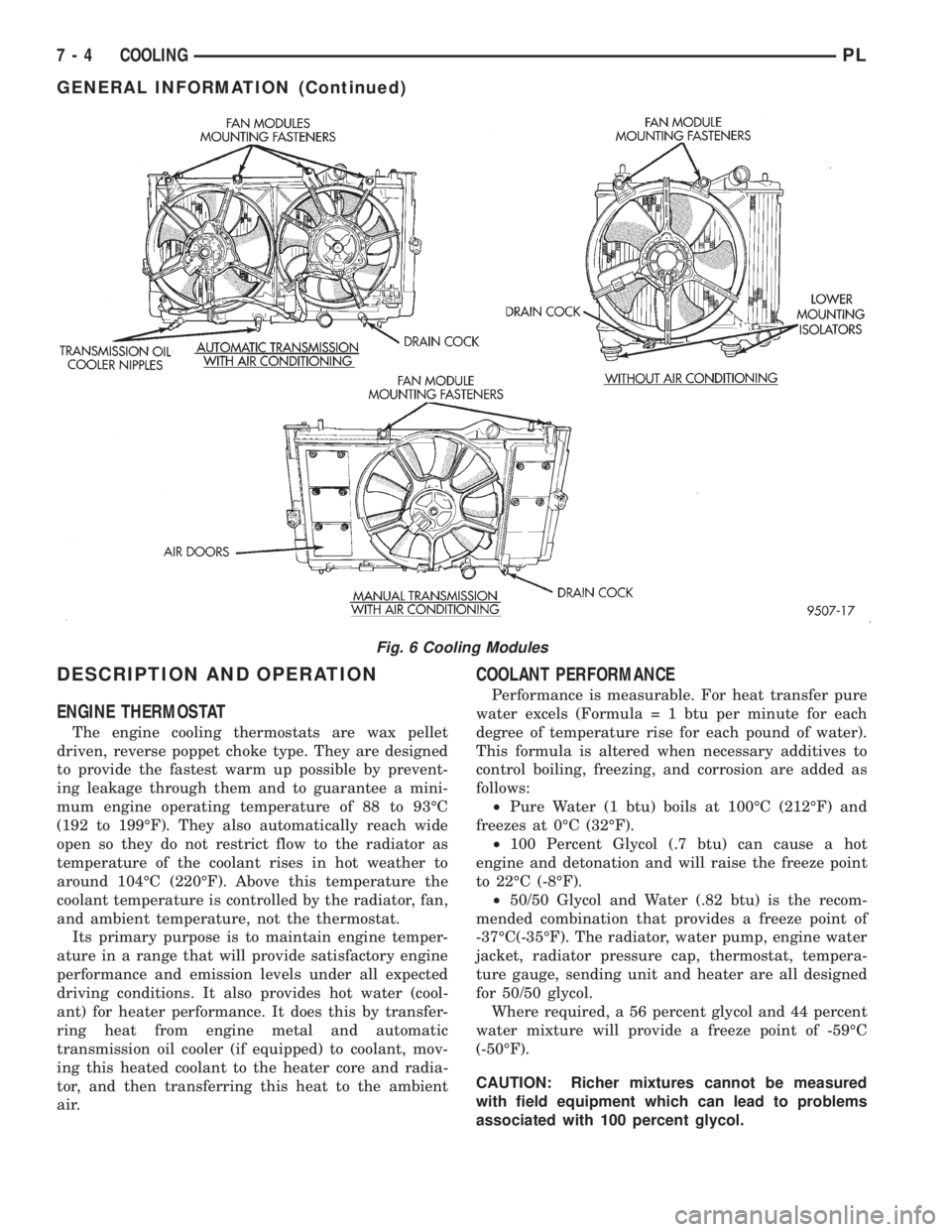
Fig. 6 Cooling Modules
7 - 4 COOLINGPL
GENERAL INFORMATION (Continued)
Page 200 of 1200
DIAGNOSIS AND TESTING
COOLING SYSTEM DIAGNOSIS
CONDITION POSSIBLE CAUSE CORRECTION
TEMPERATURE GAUGE READS
LOW1. Has a Diagnostic Trouble Code
(DTC) been set indicating a stuck
open engine thermostat?1. Refer to On Board Diagnostic in
Group 25. Replace thermostat if
necessary. If a (DTC) has not been
set, the problem may be with the
temperature gauge.
2. Is the temperature gauge (if
equipped) connected to the
temperature gauge coolant sensor
on the engine?2. Check the connector at the
engine coolant sensor. Refer to
Group 8E. Repair as necessary.
3. Is the temperature gauge (if
equipped) operating OK?3. Check Gauge operation. Refer to
Group 8E. Repair as necessary.
4. Coolant level low during cold
ambient temperature, accompanied
by poor heater performance.4. Check coolant level in the coolant
overflow/reserve tank and the
radiator. Inspect the system for
leaks. Repair as necessary. Refer to
WARNINGS outlined in this section
before removing pressure cap.
TEMPERATURE GAUGE READS
HIGH OR ENGINE COOLANT
WARNING LAMP ILLUMINATES.
COOLANT MAY OR MAY NOT BE
LOST FROM SYSTEM.1. Trailer being towed, a steep hill
being climbed, vehicle being
operated in slow moving traffic, or
engine idling during high ambient
(outside) temperatures with air
conditioning on. High altitudes
Could aggravate these conditions.1. This may be a temporary
condition and repair is not
necessary. Turn off the air
conditioning and drive the vehicle
without any of the previous
conditions. Observe the temperature
gauge the gauge should return to
the normal range. If the gauge does
not return to the normal range,
determine the cause of the
overheating and repair. Refer to
POSSIBLE CAUSES in this section.
2. Is temperature gauge (if
equipped) reading correctly?2. Check gauge. Refer to Group 8E.
Repair as necessary.
3. Is temperature warning lamp (if
equipped) illuminating
unnecessarily?3. Check warning lamp operation.
Refer to Group 8E. Repair as
necessary.
4. Coolant low in overflow/reserve
tank and radiator?4. Check for coolant leaks and
repair as necessary. Refer to
checking cooling system for leaks in
this group.
5. Pressure cap not installed tightly.
If cap is loose, boiling point of
coolant will be lowered. Also refer
to the following step 6.5. Tighten cap.
6. Poor seals at radiator cap. 6. (a) Check condition of cap and
cap seals. Refer to Radiator cap
Inspection. Replace cap if
necessary.
6. (b) Check condition of filler neck.
If neck is bent or damaged, replace
neck.
PLCOOLING 7 - 7
Page 208 of 1200
There may be internal leaks, which can be deter-
mined by removing the oil dipstick. If water globules
appear intermixed with the oil, it indicates an inter-
nal leak in the engine. If there is an internal leak,
the engine must be disassembled for repair.
PRESSURE CAP TO FILLER NECK SEAL
PRESSURE RELIEF CHECK
The pressure cap upper gasket (seal) pressure
relief can be checked by removing the overflow hose
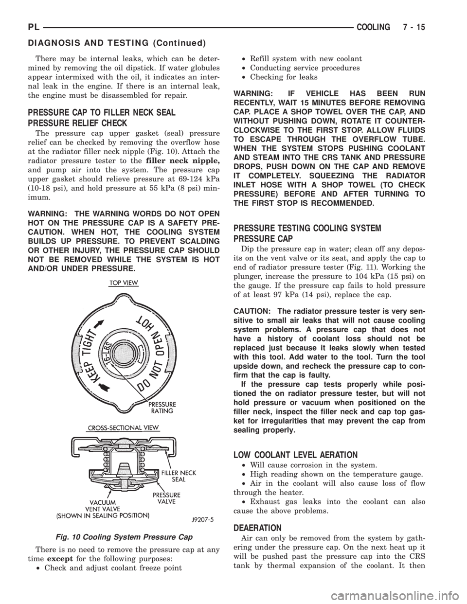
at the radiator filler neck nipple (Fig. 10). Attach the
radiator pressure tester to thefiller neck nipple,
and pump air into the system. The pressure cap
upper gasket should relieve pressure at 69-124 kPa
(10-18 psi), and hold pressure at 55 kPa (8 psi) min-
imum.
WARNING: THE WARNING WORDS DO NOT OPEN
HOT ON THE PRESSURE CAP IS A SAFETY PRE-
CAUTION. WHEN HOT, THE COOLING SYSTEM
BUILDS UP PRESSURE. TO PREVENT SCALDING
OR OTHER INJURY, THE PRESSURE CAP SHOULD
NOT BE REMOVED WHILE THE SYSTEM IS HOT
AND/OR UNDER PRESSURE.
There is no need to remove the pressure cap at any
timeexceptfor the following purposes:
²Check and adjust coolant freeze point²Refill system with new coolant
²Conducting service procedures
²Checking for leaks
WARNING: IF VEHICLE HAS BEEN RUN
RECENTLY, WAIT 15 MINUTES BEFORE REMOVING
CAP. PLACE A SHOP TOWEL OVER THE CAP, AND
WITHOUT PUSHING DOWN, ROTATE IT COUNTER-
CLOCKWISE TO THE FIRST STOP. ALLOW FLUIDS
TO ESCAPE THROUGH THE OVERFLOW TUBE.
WHEN THE SYSTEM STOPS PUSHING COOLANT
AND STEAM INTO THE CRS TANK AND PRESSURE
DROPS, PUSH DOWN ON THE CAP AND REMOVE
IT COMPLETELY. SQUEEZING THE RADIATOR
INLET HOSE WITH A SHOP TOWEL (TO CHECK
PRESSURE) BEFORE AND AFTER TURNING TO
THE FIRST STOP IS RECOMMENDED.
PRESSURE TESTING COOLING SYSTEM
PRESSURE CAP
Dip the pressure cap in water; clean off any depos-
its on the vent valve or its seat, and apply the cap to
end of radiator pressure tester (Fig. 11). Working the
plunger, increase the pressure to 104 kPa (15 psi) on
the gauge. If the pressure cap fails to hold pressure
of at least 97 kPa (14 psi), replace the cap.
CAUTION: The radiator pressure tester is very sen-
sitive to small air leaks that will not cause cooling
system problems. A pressure cap that does not
have a history of coolant loss should not be
replaced just because it leaks slowly when tested
with this tool. Add water to the tool. Turn the tool
upside down, and recheck the pressure cap to con-
firm that the cap is faulty.
If the pressure cap tests properly while posi-
tioned the on radiator pressure tester, but will not
hold pressure or vacuum when positioned on the
filler neck, inspect the filler neck and cap top gas-
ket for irregularities that may prevent the cap from
sealing properly.
LOW COOLANT LEVEL AERATION
²Will cause corrosion in the system.
²High reading shown on the temperature gauge.
²Air in the coolant will also cause loss of flow
through the heater.
²Exhaust gas leaks into the coolant can also
cause the above problems.
DEAERATION
Air can only be removed from the system by gath-
ering under the pressure cap. On the next heat up it
will be pushed past the pressure cap into the CRS
tank by thermal expansion of the coolant. It thenFig. 10 Cooling System Pressure Cap
PLCOOLING 7 - 15
DIAGNOSIS AND TESTING (Continued)
Page 234 of 1200
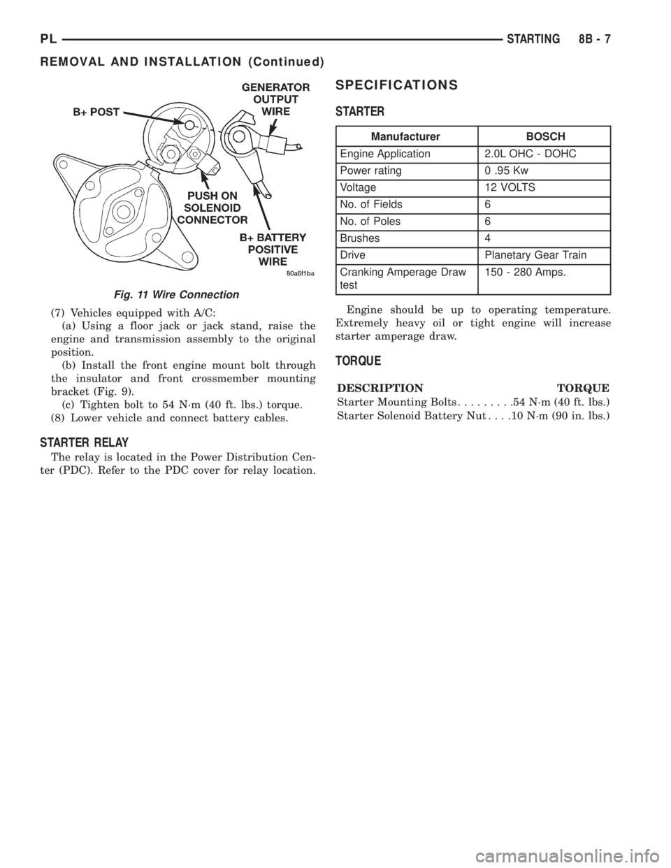
(7) Vehicles equipped with A/C:
(a) Using a floor jack or jack stand, raise the
engine and transmission assembly to the original
position.
(b) Install the front engine mount bolt through
the insulator and front crossmember mounting
bracket (Fig. 9).
(c) Tighten bolt to 54 N´m (40 ft. lbs.) torque.
(8) Lower vehicle and connect battery cables.
STARTER RELAY
The relay is located in the Power Distribution Cen-
ter (PDC). Refer to the PDC cover for relay location.
SPECIFICATIONS
STARTER
Engine should be up to operating temperature.
Extremely heavy oil or tight engine will increase
starter amperage draw.
TORQUE
DESCRIPTION TORQUE
Starter Mounting Bolts.........54N´m(40ft.lbs.)
Starter Solenoid Battery Nut. . . .10 N´m (90 in. lbs.)
Fig. 11 Wire Connection
Manufacturer BOSCH
Engine Application 2.0L OHC - DOHC
Power rating 0 .95 Kw
Voltage 12 VOLTS
No. of Fields 6
No. of Poles 6
Brushes 4
Drive Planetary Gear Train
Cranking Amperage Draw
test150 - 280 Amps.
PLSTARTING 8B - 7
REMOVAL AND INSTALLATION (Continued)
Page 237 of 1200
A battery temperature sensor located on the front
bumper beam is used to sense battery temperature.
This temperature data, along with data from moni-
tored line voltage, is used by the PCM to vary the
battery charging rate. This is done by cycling the
ground path to control the strength of the rotor mag-
netic field. The PCM then compensates and regulates
generator current output accordingly and to maintain
the proper voltage depending on battery tempera-
ture.
All vehicles are equipped with On-Board Diagnos-
tics (OBD). All OBD-sensed systems, including the
EVR (field control) circuitry, are monitored by the
PCM. Each monitored circuit is assigned a Diagnos-
tic Trouble Code (DTC). The PCM will store a DTC in
electronic memory for any failure it detects. See On-
Board Diagnostic System Test in this group for more
information.
GENERATOR
The generator is belt-driven by the engine. It is
serviced only as a complete assembly. If the genera-
tor fails for any reason, the entire assembly must be
replaced.
As the energized rotor begins to rotate within the
generator, the spinning magnetic field induces a cur-
rent into the windings of the stator coil. Once the
generator begins producing sufficient current, it also
provides the current needed to energize the rotor.
The Y type stator winding connections deliver the
induced AC current to 3 positive and 3 negative
diodes for rectification. From the diodes, rectified DC
current is delivered to the vehicle electrical system
through the generator, battery, and ground terminals.
Noise emitting from the generator may be caused
by:
²Worn, loose or defective bearings
²Loose or defective drive pulley
²Incorrect, worn, damaged or misadjusted drive
belt
²Loose mounting bolts
²Misaligned drive pulley
²Defective stator or diode
BATTERY TEMPERATURE SENSOR
The battery temperature sensor is used to deter-
mine the battery temperature. This temperature
data, along with data from monitored line voltage, is
used by the PCM to vary the battery charging rate.
System voltage will be higher at colder temperatures
and is gradually reduced at warmer temperatures.
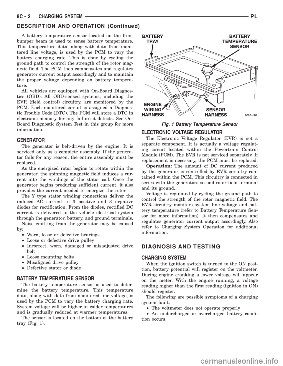
The sensor is located on the bottom of the battery
tray (Fig. 1).
ELECTRONIC VOLTAGE REGULATOR
The Electronic Voltage Regulator (EVR) is not a
separate component. It is actually a voltage regulat-
ing circuit located within the Powertrain Control
Module (PCM). The EVR is not serviced separately. If
replacement is necessary, the PCM must be replaced.
Operation:The amount of DC current produced
by the generator is controlled by EVR circuitry con-
tained within the PCM. This circuitry is connected in
series with the generators second rotor field terminal
and its ground.
Voltage is regulated by cycling the ground path to
control the strength of the rotor magnetic field. The
EVR circuitry monitors system line voltage and bat-
tery temperature (refer to Battery Temperature Sen-
sor for more information). It then compensates and
regulates generator current output accordingly. Also
refer to Charging System Operation for additional
information.
DIAGNOSIS AND TESTING
CHARGING SYSTEM
When the ignition switch is turned to the ON posi-
tion, battery potential will register on the voltmeter.
During engine cranking a lower voltage will appear
on the meter. With the engine running, a voltage
reading higher than the first reading (ignition in ON)
should register.
The following are possible symptoms of a charging
system fault:
²The voltmeter does not operate properly
²An undercharged or overcharged battery condi-
tion occurs.
Fig. 1 Battery Temperature Sensor
8C - 2 CHARGING SYSTEMPL
DESCRIPTION AND OPERATION (Continued)
Page 250 of 1200
IGNITION SYSTEM
CONTENTS
page page
GENERAL INFORMATION
INTRODUCTION......................... 1
DESCRIPTION AND OPERATION
AUTOMATIC SHUTDOWN RELAY............ 3
CAMSHAFT POSITION SENSOR............. 4
COMBINATION ENGINE COOLANT
TEMPERATURE SENSOR................. 5
CRANKSHAFT POSITION SENSOR........... 4
ELECTRONIC IGNITION COILS.............. 3
IGNITION INTERLOCK.................... 7
IGNITION SWITCH....................... 7
IGNITION SYSTEM....................... 1
INTAKE AIR TEMPERATURE SENSOR........ 6
KNOCK SENSOR......................... 6
LOCK KEY CYLINDER..................... 7
MANIFOLD ABSOLUTE PRESSURE SENSOR
(MAP)............................... 6
POWERTRAIN CONTROL MODULE.......... 2
SPARK PLUG CABLES.................... 2
SPARK PLUGS.......................... 2
THROTTLE POSITION SENSOR (TPS)........ 6
DIAGNOSIS AND TESTING
CAMSHAFT POSITION SENSOR AND
CRANKSHAFT POSITION SENSOR......... 9
CHECK COIL TEST....................... 8
ENGINE COOLANT TEMPERATURE SENSOR . . . 9
FAILURE TO START TESTÐ2.0/2.4L......... 8
IGNITION TIMING PROCEDURE............. 9
INTAKE AIR TEMPERATURE SENSOR........ 9
MANIFOLD ABSOLUTE PRESSURE (MAP)
SENSOR TEST......................... 9
SPARK PLUG CONDITION................ 10TESTING FOR SPARK AT COILÐ2.0/2.4L..... 7
THROTTLE POSITION SENSOR............. 9
REMOVAL AND INSTALLATION
AUTOMATIC SHUTDOWN RELAY........... 13
CAMSHAFT POSITION SENSORÐDOHC..... 14
CAMSHAFT POSITION SENSORÐSOHC..... 13
COMBINATION ENGINE COOLANT
TEMPERATURE SENSORÐDOHC........ 15
COMBINATION ENGINE COOLANT
TEMPERATURE SENSORÐSOHC......... 15
CRANKSHAFT POSITION SENSOR.......... 15
IGNITION COIL......................... 13
IGNITION INTERLOCK................... 18
IGNITION SWITCH...................... 16
LOCK CYLINDER HOUSING............... 18
LOCK KEY CYLINDER.................... 17
MAP/IAT SENSORÐDOHC................ 16
MAP/IAT SENSORÐSOHC................ 16
POWERTRAIN CONTROL MODULE (PCM) . . . 12
SPARK PLUG CABLE SERVICE............ 13
SPARK PLUG SERVICE.................. 12
SPARK PLUG TUBES.................... 13
THROTTLE POSITION SENSOR............ 16
SPECIFICATIONS
FIRING ORDERÐ2.0L................... 18
IGNITION COIL......................... 19
SPARK PLUG CABLE RESISTANCEÐDOHC . . 18
SPARK PLUG CABLE RESISTANCEÐSOHC . . . 18
SPARK PLUG.......................... 19
TORQUE SPECIFICATION................. 18
VECI LABEL........................... 18
GENERAL INFORMATION
INTRODUCTION
This section describes the electronic ignition sys-
tem for the 2.0L engines used in Neon vehicles.
The On-Board Diagnostics Section in Group 25
describes diagnostic trouble codes.
Group 0, Lubrication and Maintenance, contains
general maintenance information for ignition relateditems. The Owner's Manual also contains mainte-
nance information.DESCRIPTION AND OPERATION
IGNITION SYSTEM
Ignition system operation and diagnostics, are
identical for 2.0L Single Overhead Cam (SOHC) and
2.0L Duel Overhead Cam (DOHC) engines.
PLIGNITION SYSTEM 8D - 1
Page 251 of 1200
The major difference between the two engines is
component location which affects the ignition system
service procedures. There are various sensors that
are in different locations due to a different cylinder
head and intake manifold.
The 2.0L engines use a fixed ignition timing sys-
tem. The distributorless electronic ignition system is
referred to as the Direct Ignition System (DIS).
Basic ignition timing is not adjustable.The
Powertrain Control Module (PCM) determines spark
advance. The system's three main components are
the coil pack, crankshaft position sensor, and cam-
shaft position sensor.
POWERTRAIN CONTROL MODULE
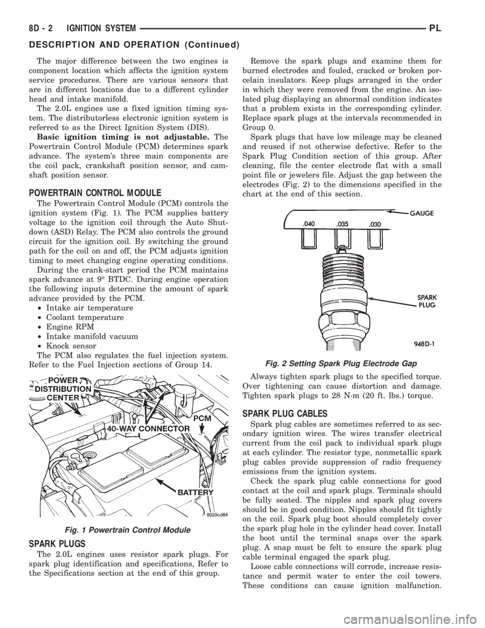
The Powertrain Control Module (PCM) controls the
ignition system (Fig. 1). The PCM supplies battery
voltage to the ignition coil through the Auto Shut-
down (ASD) Relay. The PCM also controls the ground
circuit for the ignition coil. By switching the ground
path for the coil on and off, the PCM adjusts ignition
timing to meet changing engine operating conditions.
During the crank-start period the PCM maintains
spark advance at 9É BTDC. During engine operation
the following inputs determine the amount of spark
advance provided by the PCM.
²Intake air temperature
²Coolant temperature
²Engine RPM
²Intake manifold vacuum
²Knock sensor
The PCM also regulates the fuel injection system.
Refer to the Fuel Injection sections of Group 14.
SPARK PLUGS
The 2.0L engines uses resistor spark plugs. For
spark plug identification and specifications, Refer to
the Specifications section at the end of this group.Remove the spark plugs and examine them for
burned electrodes and fouled, cracked or broken por-
celain insulators. Keep plugs arranged in the order
in which they were removed from the engine. An iso-
lated plug displaying an abnormal condition indicates
that a problem exists in the corresponding cylinder.
Replace spark plugs at the intervals recommended in
Group 0.
Spark plugs that have low mileage may be cleaned
and reused if not otherwise defective. Refer to the
Spark Plug Condition section of this group. After
cleaning, file the center electrode flat with a small
point file or jewelers file. Adjust the gap between the
electrodes (Fig. 2) to the dimensions specified in the
chart at the end of this section.
Always tighten spark plugs to the specified torque.
Over tightening can cause distortion and damage.
Tighten spark plugs to 28 N´m (20 ft. lbs.) torque.
SPARK PLUG CABLES
Spark plug cables are sometimes referred to as sec-
ondary ignition wires. The wires transfer electrical
current from the coil pack to individual spark plugs
at each cylinder. The resistor type, nonmetallic spark
plug cables provide suppression of radio frequency
emissions from the ignition system.
Check the spark plug cable connections for good
contact at the coil and spark plugs. Terminals should
be fully seated. The nipples and spark plug covers
should be in good condition. Nipples should fit tightly
on the coil. Spark plug boot should completely cover
the spark plug hole in the cylinder head cover. Install
the boot until the terminal snaps over the spark
plug. A snap must be felt to ensure the spark plug
cable terminal engaged the spark plug.
Loose cable connections will corrode, increase resis-
tance and permit water to enter the coil towers.
These conditions can cause ignition malfunction.
Fig. 1 Powertrain Control Module
Fig. 2 Setting Spark Plug Electrode Gap
8D - 2 IGNITION SYSTEMPL
DESCRIPTION AND OPERATION (Continued)
Page 258 of 1200
ply circuit shorts to ground, neither sensor will pro-
duce a signal (output voltage to the PCM).
When the ignition key is turned and left in the On
position, the PCM automatically energizes the Auto
Shutdown (ASD) relay. However, the controller de-en-
ergizes the relay within one second because it has
not received a camshaft position sensor signal indi-
cating engine rotation.
During cranking, the ASD relay will not energize
until the PCM receives a camshaft position sensor
signal. Secondly, the ASD relay remains energized
only if the controller senses a crankshaft position
sensor signal immediately after detecting the cam-
shaft position sensor signal.
(1) Check battery voltage. Voltage should approxi-
mately 12.66 volts or higher to perform failure to
start test.
(2) Disconnect the harness connector from the coil
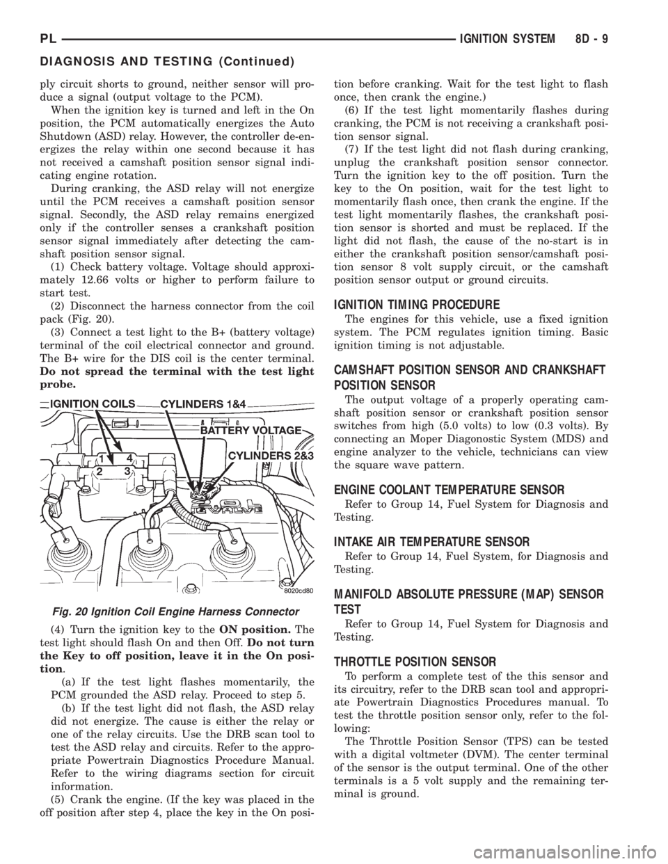
pack (Fig. 20).
(3) Connect a test light to the B+ (battery voltage)
terminal of the coil electrical connector and ground.
The B+ wire for the DIS coil is the center terminal.
Do not spread the terminal with the test light
probe.
(4) Turn the ignition key to theON position.The
test light should flash On and then Off.Do not turn
the Key to off position, leave it in the On posi-
tion.
(a) If the test light flashes momentarily, the
PCM grounded the ASD relay. Proceed to step 5.
(b) If the test light did not flash, the ASD relay
did not energize. The cause is either the relay or
one of the relay circuits. Use the DRB scan tool to
test the ASD relay and circuits. Refer to the appro-
priate Powertrain Diagnostics Procedure Manual.
Refer to the wiring diagrams section for circuit
information.
(5) Crank the engine. (If the key was placed in the
off position after step 4, place the key in the On posi-tion before cranking. Wait for the test light to flash
once, then crank the engine.)
(6) If the test light momentarily flashes during
cranking, the PCM is not receiving a crankshaft posi-
tion sensor signal.
(7) If the test light did not flash during cranking,
unplug the crankshaft position sensor connector.
Turn the ignition key to the off position. Turn the
key to the On position, wait for the test light to
momentarily flash once, then crank the engine. If the
test light momentarily flashes, the crankshaft posi-
tion sensor is shorted and must be replaced. If the
light did not flash, the cause of the no-start is in
either the crankshaft position sensor/camshaft posi-
tion sensor 8 volt supply circuit, or the camshaft
position sensor output or ground circuits.
IGNITION TIMING PROCEDURE
The engines for this vehicle, use a fixed ignition
system. The PCM regulates ignition timing. Basic
ignition timing is not adjustable.
CAMSHAFT POSITION SENSOR AND CRANKSHAFT
POSITION SENSOR
The output voltage of a properly operating cam-
shaft position sensor or crankshaft position sensor
switches from high (5.0 volts) to low (0.3 volts). By
connecting an Moper Diagonostic System (MDS) and
engine analyzer to the vehicle, technicians can view
the square wave pattern.
ENGINE COOLANT TEMPERATURE SENSOR
Refer to Group 14, Fuel System for Diagnosis and
Testing.
INTAKE AIR TEMPERATURE SENSOR
Refer to Group 14, Fuel System, for Diagnosis and
Testing.
MANIFOLD ABSOLUTE PRESSURE (MAP) SENSOR
TEST
Refer to Group 14, Fuel System for Diagnosis and
Testing.
THROTTLE POSITION SENSOR
To perform a complete test of the this sensor and
its circuitry, refer to the DRB scan tool and appropri-
ate Powertrain Diagnostics Procedures manual. To
test the throttle position sensor only, refer to the fol-
lowing:
The Throttle Position Sensor (TPS) can be tested
with a digital voltmeter (DVM). The center terminal
of the sensor is the output terminal. One of the other
terminals is a 5 volt supply and the remaining ter-
minal is ground.
Fig. 20 Ignition Coil Engine Harness Connector
PLIGNITION SYSTEM 8D - 9
DIAGNOSIS AND TESTING (Continued)
Page 259 of 1200
Connect the DVM between the center and sensor
ground terminal. Refer to Group 8W - Wiring Dia-
grams for correct pinout.
With the ignition switch in the ON position, check
the output voltage at the center terminal wire of the
connector. Check the output voltage at idle and at
Wide-Open-Throttle (WOT). At idle, TPS output volt-
age should be approximately 0.38 volts to 1.2 volts.
At wide open throttle, TPS output voltage should be
approximately 3.1 volts to 4.4 volts. The output volt-
age should gradually increase as the throttle plate
moves slowly from idle to WOT.
Check for spread terminals at the sensor and PCM
connections before replacing the TPS.
SPARK PLUG CONDITION
NORMAL OPERATING CONDITIONS
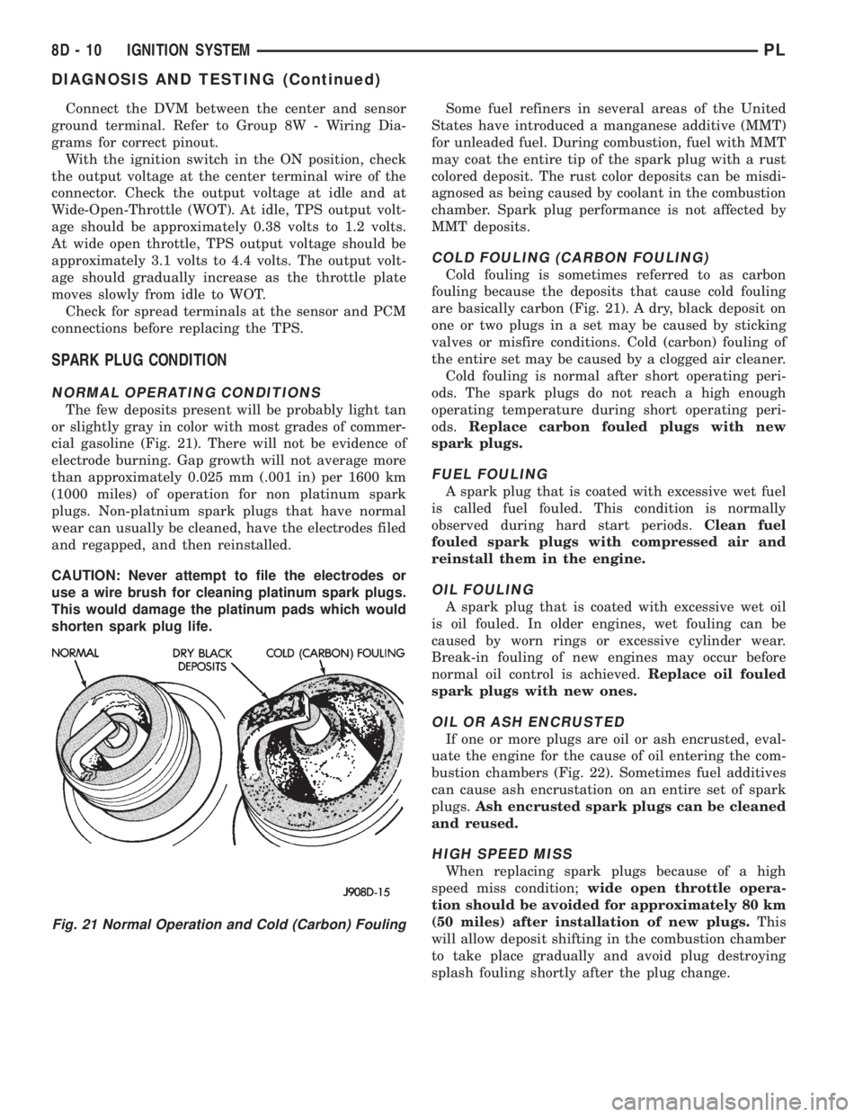
The few deposits present will be probably light tan
or slightly gray in color with most grades of commer-
cial gasoline (Fig. 21). There will not be evidence of
electrode burning. Gap growth will not average more
than approximately 0.025 mm (.001 in) per 1600 km
(1000 miles) of operation for non platinum spark
plugs. Non-platnium spark plugs that have normal
wear can usually be cleaned, have the electrodes filed
and regapped, and then reinstalled.
CAUTION: Never attempt to file the electrodes or
use a wire brush for cleaning platinum spark plugs.
This would damage the platinum pads which would
shorten spark plug life.Some fuel refiners in several areas of the United
States have introduced a manganese additive (MMT)
for unleaded fuel. During combustion, fuel with MMT
may coat the entire tip of the spark plug with a rust
colored deposit. The rust color deposits can be misdi-
agnosed as being caused by coolant in the combustion
chamber. Spark plug performance is not affected by
MMT deposits.
COLD FOULING (CARBON FOULING)
Cold fouling is sometimes referred to as carbon
fouling because the deposits that cause cold fouling
are basically carbon (Fig. 21). A dry, black deposit on
one or two plugs in a set may be caused by sticking
valves or misfire conditions. Cold (carbon) fouling of
the entire set may be caused by a clogged air cleaner.
Cold fouling is normal after short operating peri-
ods. The spark plugs do not reach a high enough
operating temperature during short operating peri-
ods.Replace carbon fouled plugs with new
spark plugs.
FUEL FOULING
A spark plug that is coated with excessive wet fuel
is called fuel fouled. This condition is normally
observed during hard start periods.Clean fuel
fouled spark plugs with compressed air and
reinstall them in the engine.
OIL FOULING
A spark plug that is coated with excessive wet oil
is oil fouled. In older engines, wet fouling can be
caused by worn rings or excessive cylinder wear.
Break-in fouling of new engines may occur before
normal oil control is achieved.Replace oil fouled
spark plugs with new ones.
OIL OR ASH ENCRUSTED
If one or more plugs are oil or ash encrusted, eval-
uate the engine for the cause of oil entering the com-
bustion chambers (Fig. 22). Sometimes fuel additives
can cause ash encrustation on an entire set of spark
plugs.Ash encrusted spark plugs can be cleaned
and reused.
HIGH SPEED MISS
When replacing spark plugs because of a high
speed miss condition;wide open throttle opera-
tion should be avoided for approximately 80 km
(50 miles) after installation of new plugs.This
will allow deposit shifting in the combustion chamber
to take place gradually and avoid plug destroying
splash fouling shortly after the plug change.
Fig. 21 Normal Operation and Cold (Carbon) Fouling
8D - 10 IGNITION SYSTEMPL
DIAGNOSIS AND TESTING (Continued)