radio DODGE NEON 1999 Service Repair Manual
[x] Cancel search | Manufacturer: DODGE, Model Year: 1999, Model line: NEON, Model: DODGE NEON 1999Pages: 1200, PDF Size: 35.29 MB
Page 157 of 1200
and performance characteristics of the ABS. See the
ABS System Operation Section in this group of the
service manual to familiarize yourself with the oper-
ating principles of the ITT Teves Mark 20 ABS sys-
tem.
ABS SERVICE PRECAUTIONS
The ABS uses an electronic control module, the
CAB. This module is designed to withstand normal
current draws associated with vehicle operation.
Care must be taken to avoid overloading the CAB
circuits.In testing for open or short circuits, do
not ground or apply voltage to any of the cir-
cuits unless instructed to do so for a diagnostic
procedure.These circuits should only be tested
using a high impedance multi-meter or the DRB
tester as described in this section. Power should
never be removed or applied to any control module
with the ignition in the ON position. Before removing
or connecting battery cables, fuses, or connectors,
always turn the ignition to the OFF position.
CAUTION: Use only factory wiring harnesses. Do
not cut or splice wiring to the brake circuits. The
addition of after-market electrical equipment (car
phone, radar detector, citizen band radio, trailer
lighting, trailer brakes, ect.) on a vehicle equippedwith antilock brakes may affect the function of the
antilock brake system.
ABS WIRING DIAGRAM INFORMATION
During the diagnosis of the antilock brake system
it may become necessary to reference the wiring dia-
grams covering the antilock brake system and its
components. For wiring diagrams refer to Antilock
Brakes in Group 8W of this service manual. This
group will provide you with the wiring diagrams and
the circuit description and operation information cov-
ering the antilock brake system.
ABS DIAGNOSTICS MANUAL
Detailed procedures for diagnosing specific ABS
conditions are covered in the diagnostics manual cov-
ering the ITT Teves Mark 20 ABS system. The fol-
lowing information is presented to give the
technician a general background on the diagnostic
capabilities of the ITT Teves Mark 20 ABS system.
Please refer to the above mentioned manual for any
further electronic diagnostics and service procedures
that are required.
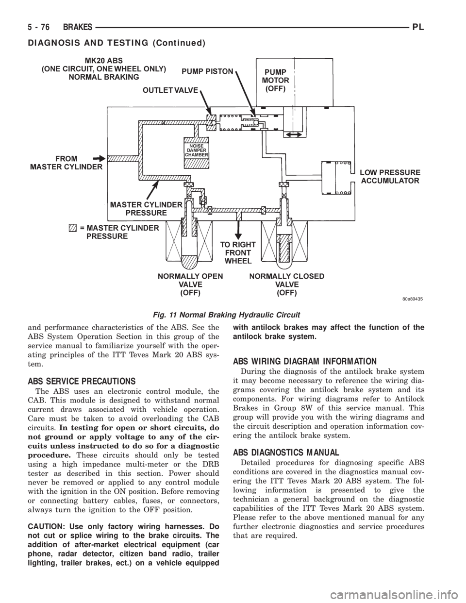
Fig. 11 Normal Braking Hydraulic Circuit
5 - 76 BRAKESPL
DIAGNOSIS AND TESTING (Continued)
Page 221 of 1200
²Fuel pump fuse (20 Amp)
²Interior lamps fuse (10 Amp)
(6) If there is any reading with fuses removed
there is a current draw or short circuit in the wiring.
Refer to Group 8W, Wiring Diagrams. If OK go to
Step 7.
(7) Install interior lamp fuse. After installing fuse,
the current can reach 250 milliamperes. After time-out the reading should not exceed 8 milliamperes. If
NOT OK go to Step 8. If OK go to Step 9.
²Ignition key lamp system
²Radio
²Remote keyless entry module, if equipped
(8) Disconnect radio and ignition switch key lamp
one component at time, to see if any component is at
fault. If the high reading is not eliminated there is a
short circuit in the wiring. Refer to Group 8W, Wir-
ing Diagrams.
CAUTION: Always disconnect the meter before
opening a door.
(9) Remove interior lamps fuse and install the fuel
pump fuse. The reading should be between 1-3 milli-
amperes. If reading is higher than 3 milliamperes:
(a) Disconnect Powertrain Control Module.
(b) If reading drops to zero, replace Powertrain
Control Module.
(c) If reading remains the same there is a cur-
rent draw or short circuit in the A14 circuit. Refer
to Group 8W, Wiring Diagrams.
BATTERY DIAGNOSIS AND TESTING
STEPS POSSIBLE CAUSE CORRECTION
VISUAL INSPECTION
Check for possible damage to
battery and clean battery.(1) Loose battery post, Cracked
battery cover or case, Leaks or Any
other physical
(2) Battery OK.(1) Replace Battery
(2) Check state of charge. Refer to
Test Indicator.
TEST INDICATOR
Check Charge Eye Color(1) GREEN
(2) BLACK
(3) CLEAR(1) Battery is charged. Perform
Battery 0pen Circuit Voltage Test
(2) Perform Battery Charging
procedure.
(3) Replace Battery.
BATTERY OPEN CIRCUIT
VOLTAGE TEST(1) Battery is above 12.40 Volts
(2) Battery is below 12.40 Volts.(1) Perform the Battery Load Test.
(2) Perform Battery Charging
procedure.
BATTERY CHARGING (1) Battery accepted Charge.
(2) Battery will not accept charge(1) Ensure that the indicator eye is
GREEN and perform Battery 0pen
Circuit Voltage Test
(2) Perform Charging a Completely
Discharged Battery.
BATTERY LOAD TEST (1) Acceptable minimum voltage.
(2) Unacceptable minimum voltage(1) Battery is OK to put in use,
perform Battery Ignition Off Draw
Test.
(2) Replace Battery and perform
Battery Ignition Off Draw Test.
CHARGING A COMPLETELY
DISCHARGED BATTERY(1) Battery accepted charge.
(2) Battery will not accept charge.(1) Ensure that the indicator eye is
GREEN and perform Battery 0pen
Circuit Voltage Test.
(2) Replace Battery.
IGNITION OFF DRAW TEST (1) IOD is 5-25 Milliamperes.
(2) IOD Exceeds 25 Milliamperes.(1) Vehicle is normal.
(2) Eliminate excess IOD draw.
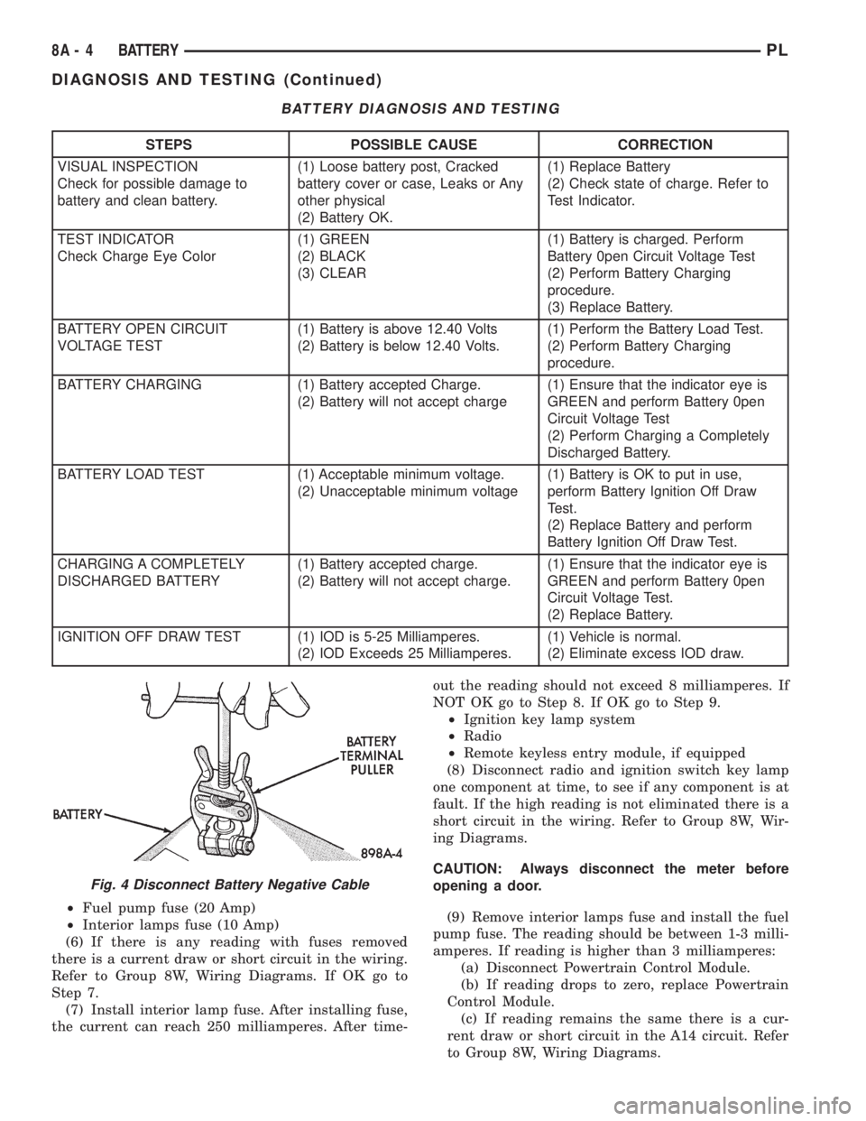
Fig. 4 Disconnect Battery Negative Cable
8A - 4 BATTERYPL
DIAGNOSIS AND TESTING (Continued)
Page 251 of 1200
The major difference between the two engines is
component location which affects the ignition system
service procedures. There are various sensors that
are in different locations due to a different cylinder
head and intake manifold.
The 2.0L engines use a fixed ignition timing sys-
tem. The distributorless electronic ignition system is
referred to as the Direct Ignition System (DIS).
Basic ignition timing is not adjustable.The
Powertrain Control Module (PCM) determines spark
advance. The system's three main components are
the coil pack, crankshaft position sensor, and cam-
shaft position sensor.
POWERTRAIN CONTROL MODULE
The Powertrain Control Module (PCM) controls the
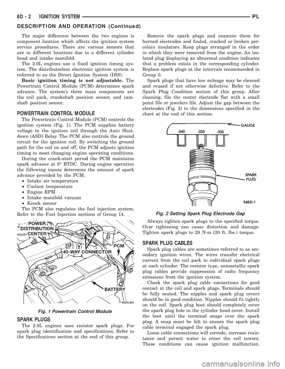
ignition system (Fig. 1). The PCM supplies battery
voltage to the ignition coil through the Auto Shut-
down (ASD) Relay. The PCM also controls the ground
circuit for the ignition coil. By switching the ground
path for the coil on and off, the PCM adjusts ignition
timing to meet changing engine operating conditions.
During the crank-start period the PCM maintains
spark advance at 9É BTDC. During engine operation
the following inputs determine the amount of spark
advance provided by the PCM.
²Intake air temperature
²Coolant temperature
²Engine RPM
²Intake manifold vacuum
²Knock sensor
The PCM also regulates the fuel injection system.
Refer to the Fuel Injection sections of Group 14.
SPARK PLUGS
The 2.0L engines uses resistor spark plugs. For
spark plug identification and specifications, Refer to
the Specifications section at the end of this group.Remove the spark plugs and examine them for
burned electrodes and fouled, cracked or broken por-
celain insulators. Keep plugs arranged in the order
in which they were removed from the engine. An iso-
lated plug displaying an abnormal condition indicates
that a problem exists in the corresponding cylinder.
Replace spark plugs at the intervals recommended in
Group 0.
Spark plugs that have low mileage may be cleaned
and reused if not otherwise defective. Refer to the
Spark Plug Condition section of this group. After
cleaning, file the center electrode flat with a small
point file or jewelers file. Adjust the gap between the
electrodes (Fig. 2) to the dimensions specified in the
chart at the end of this section.
Always tighten spark plugs to the specified torque.
Over tightening can cause distortion and damage.
Tighten spark plugs to 28 N´m (20 ft. lbs.) torque.
SPARK PLUG CABLES
Spark plug cables are sometimes referred to as sec-
ondary ignition wires. The wires transfer electrical
current from the coil pack to individual spark plugs
at each cylinder. The resistor type, nonmetallic spark
plug cables provide suppression of radio frequency
emissions from the ignition system.
Check the spark plug cable connections for good
contact at the coil and spark plugs. Terminals should
be fully seated. The nipples and spark plug covers
should be in good condition. Nipples should fit tightly
on the coil. Spark plug boot should completely cover
the spark plug hole in the cylinder head cover. Install
the boot until the terminal snaps over the spark
plug. A snap must be felt to ensure the spark plug
cable terminal engaged the spark plug.
Loose cable connections will corrode, increase resis-
tance and permit water to enter the coil towers.
These conditions can cause ignition malfunction.
Fig. 1 Powertrain Control Module
Fig. 2 Setting Spark Plug Electrode Gap
8D - 2 IGNITION SYSTEMPL
DESCRIPTION AND OPERATION (Continued)
Page 261 of 1200
other operating conditions are causing engine over-
heating.
SPARK PLUG OVERHEATING
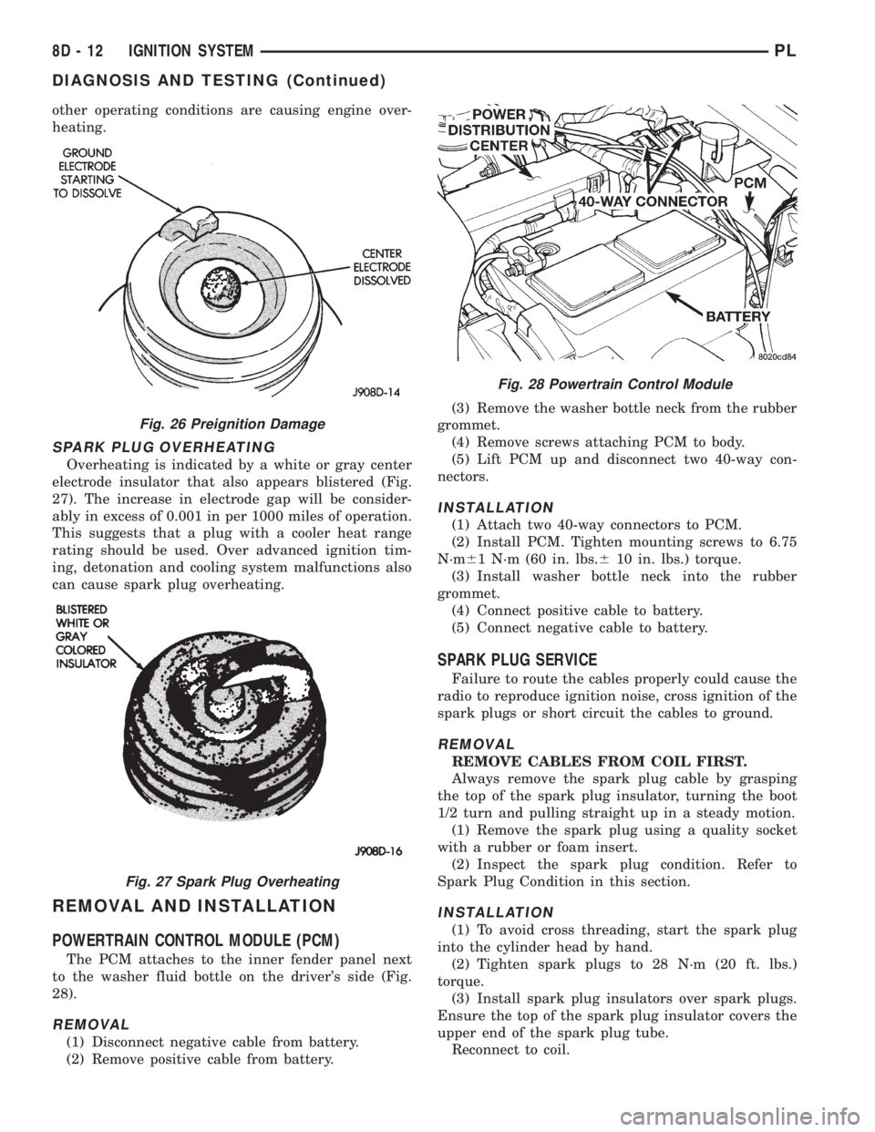
Overheating is indicated by a white or gray center
electrode insulator that also appears blistered (Fig.
27). The increase in electrode gap will be consider-
ably in excess of 0.001 in per 1000 miles of operation.
This suggests that a plug with a cooler heat range
rating should be used. Over advanced ignition tim-
ing, detonation and cooling system malfunctions also
can cause spark plug overheating.
REMOVAL AND INSTALLATION
POWERTRAIN CONTROL MODULE (PCM)
The PCM attaches to the inner fender panel next
to the washer fluid bottle on the driver's side (Fig.
28).
REMOVAL
(1) Disconnect negative cable from battery.
(2) Remove positive cable from battery.(3) Remove the washer bottle neck from the rubber
grommet.
(4) Remove screws attaching PCM to body.
(5) Lift PCM up and disconnect two 40-way con-
nectors.
INSTALLATION
(1) Attach two 40-way connectors to PCM.
(2) Install PCM. Tighten mounting screws to 6.75
N´m61 N´m (60 in. lbs.610 in. lbs.) torque.
(3) Install washer bottle neck into the rubber
grommet.
(4) Connect positive cable to battery.
(5) Connect negative cable to battery.
SPARK PLUG SERVICE
Failure to route the cables properly could cause the
radio to reproduce ignition noise, cross ignition of the
spark plugs or short circuit the cables to ground.
REMOVAL
REMOVE CABLES FROM COIL FIRST.
Always remove the spark plug cable by grasping
the top of the spark plug insulator, turning the boot
1/2 turn and pulling straight up in a steady motion.
(1) Remove the spark plug using a quality socket
with a rubber or foam insert.
(2) Inspect the spark plug condition. Refer to
Spark Plug Condition in this section.
INSTALLATION
(1) To avoid cross threading, start the spark plug
into the cylinder head by hand.
(2) Tighten spark plugs to 28 N´m (20 ft. lbs.)
torque.
(3) Install spark plug insulators over spark plugs.
Ensure the top of the spark plug insulator covers the
upper end of the spark plug tube.
Reconnect to coil.
Fig. 26 Preignition Damage
Fig. 27 Spark Plug Overheating
Fig. 28 Powertrain Control Module
8D - 12 IGNITION SYSTEMPL
DIAGNOSIS AND TESTING (Continued)
Page 262 of 1200
SPARK PLUG CABLE SERVICE
Failure to route the cables properly could cause the
radio to reproduce ignition noise, cross ignition of the
spark plugs or short circuit the cables to ground.
REMOVAL
Remove spark plug cable from coil frist.
Always remove the spark plug cable by grasping
the top of the spark plug insulator, turning the boot
1/2 turn and pulling straight up in a steady motion.
INSTALLATION
Install spark plug insulators over spark plugs.
Ensure the top of the spark plug insulator covers the
upper end of the spark plug tube.The connect the
other end to coil pack. OnSOHCengines, be sure
that dual plastic clip holds #1,#2 cables off of valve
cover and that PCV hose plastic clip holds #3 cable
away from metal PCV clamp and edge of air duct. On
DOHC, be sure that the plastic clip on PCV hose is
positioned so that cable clip is beneath hose, and that
#1 cable is snapped into this clip to protect it from
metal PCV clamp.
SPARK PLUG TUBES
The spark plugs tubes are pressed into the cylinder
head. Sealant is applied to the end of the tube before
installation. For engine information, refer to Group
9, Engines.
IGNITION COIL
SOHC/DOHC
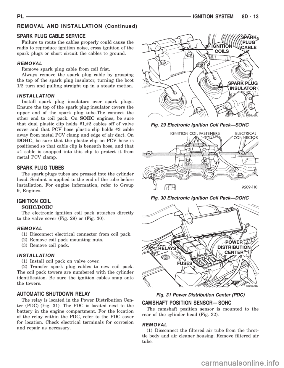
The electronic ignition coil pack attaches directly
to the valve cover (Fig. 29) or (Fig. 30).
REMOVAL
(1) Disconnect electrical connector from coil pack.
(2) Remove coil pack mounting nuts.
(3) Remove coil pack.
INSTALLATION
(1) Install coil pack on valve cover.
(2) Transfer spark plug cables to new coil pack.
The coil pack towers are numbered with the cylinder
identification. Be sure the ignition cables snap onto
the towers.
AUTOMATIC SHUTDOWN RELAY
The relay is located in the Power Distribution Cen-
ter (PDC) (Fig. 31). The PDC is located next to the
battery in the engine compartment. For the location
of the relay within the PDC, refer to the PDC cover
for location. Check electrical terminals for corrosion
and repair as necessary.CAMSHAFT POSITION SENSORÐSOHC
The camshaft position sensor is mounted to the
rear of the cylinder head (Fig. 32).
REMOVAL
(1) Disconnect the filtered air tube from the throt-
tle body and air cleaner housing. Remove filtered air
tube.
Fig. 29 Electronic Ignition Coil PackÐSOHC
Fig. 30 Electronic Ignition Coil PackÐDOHC
Fig. 31 Power Distribution Center (PDC)
PLIGNITION SYSTEM 8D - 13
REMOVAL AND INSTALLATION (Continued)
Page 270 of 1200
INSTRUMENT PANEL AND SYSTEMS
CONTENTS
page page
GENERAL INFORMATION
INTRODUCTION......................... 1
DESCRIPTION AND OPERATION
DOME LAMP............................ 1
ELECTRONIC DIGITAL CLOCK.............. 1
INSTRUMENT CLUSTER................... 2
WARNING AND INDICATOR LAMPS......... 2
DIAGNOSIS AND TESTING
AIRBAG WARNING SYSTEM............... 2
BRAKE SYSTEM WARNING LAMP TEST...... 2
FOG LAMP SWITCH TEST................. 2
FUEL TANK SENDING UNIT TEST........... 3
HEADLAMP SWITCH TEST................. 3
HEATER A/C BLOWER SWITCH TEST........ 3
HEATER BLOWER SWITCH TEST............ 3
INDIVIDUAL GAUGE INOPERATIVE.......... 4
INSTRUMENT PANEL AND COMPONENTS.... 4
LOW OIL PRESSURE WARNING LAMP TEST . . 4
MULTIPLE GAUGE INOPERATIVE TEST....... 4
SEAT BELT REMINDER SYSTEM TEST....... 6
SENDING UNIT......................... 6
SERVICE ENGINE SOON INDICATOR......... 6
VEHICLE SPEED SENSOR TEST............. 6
REMOVAL AND INSTALLATION
ASH RECEIVER RETAINER AND LAMP....... 6
CENTER BEZEL.......................... 6
CIGAR LIGHTER RECEPTACLE.............. 6
CLUSTER LAMP......................... 7
CLUSTER PRINTED CIRCUIT BOARD........ 7CLUSTER.............................. 7
DOME LENS/LAMP....................... 8
FLOOR CONSOLE........................ 8
GAUGE................................ 8
GLOVE BOX DOOR/BIN................... 8
GLOVE BOX SWITCH/LAMP................ 9
HEADLAMP SWITCH..................... 9
HEATER A/C CONTROL BLOWER SWITCH . . . 10
HEATER A/C CONTROL LAMP............ 10
HEATER A/C CONTROL................... 9
HEATER CONTROL BLOWER SWITCH....... 10
IGNITION KEY LAMP.................... 10
INSTRUMENT PANEL.................... 10
LEFT TRIM PANEL...................... 10
ODOMETER............................ 10
RADIO................................ 12
REAR WINDOW DEFOGGER AND/OR FOG
LAMP SWITCH....................... 12
RIGHT TRIM PANEL..................... 12
SHIFTER KNOB......................... 13
STEERING COLUMN COVER LINER......... 13
STEERING COLUMN COVER.............. 13
STEERING COLUMN SHROUDS............ 13
TOP COVER AND CLUSTER BEZEL
REMOVAL........................... 14
TRANSMISSION RANGE INDICATOR LAMP . . 14
TRUNK LAMP/LENS..................... 14
VEHICLE SPEED SENSOR................ 14
GENERAL INFORMATION
INTRODUCTION
The purpose of the dash gauges and indicator
lamps is to keep the driver informed about the oper-
ating condition of the vehicle. If an abnormal condi-
tion occurs, the driver is informed by indicator lamp.
The driver can seek service before damage occurs.
Indicator lamps use ON/OFF switch functions for
operation, while gauges use a sending unit or sensor.
DESCRIPTION AND OPERATION
DOME LAMP
The Dome Lamp operates when a door is open or
when the headlamp switch is placed in courtesy posi-
tion.
ELECTRONIC DIGITAL CLOCK
The electronic digital clock is in the radio. The
clock and radio each use the display panel built into
the radio. A digital readout indicates the time in
hours and minutes whenever the ignition switch is in
the ON or ACC position.
PLINSTRUMENT PANEL AND SYSTEMS 8E - 1
Page 271 of 1200
When the ignition switch is in the OFF position, or
when the radio frequency is being displayed, time
keeping is accurately maintained.
The procedure for setting the clock varies slightly
with each radio. The correct procedure is described in
the individual radio operating instructions. Refer to
the Owner's Manual supplied with the vehicle.
INSTRUMENT CLUSTER
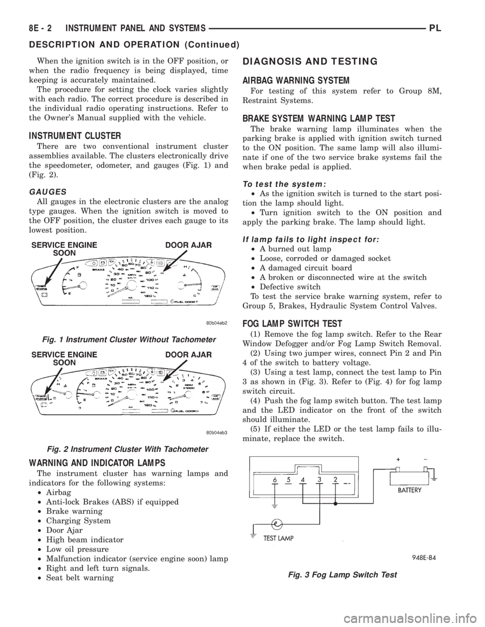
There are two conventional instrument cluster
assemblies available. The clusters electronically drive
the speedometer, odometer, and gauges (Fig. 1) and
(Fig. 2).
GAUGES
All gauges in the electronic clusters are the analog
type gauges. When the ignition switch is moved to
the OFF position, the cluster drives each gauge to its
lowest position.
WARNING AND INDICATOR LAMPS
The instrument cluster has warning lamps and
indicators for the following systems:
²Airbag
²Anti-lock Brakes (ABS) if equipped
²Brake warning
²Charging System
²Door Ajar
²High beam indicator
²Low oil pressure
²Malfunction indicator (service engine soon) lamp
²Right and left turn signals.
²Seat belt warning
DIAGNOSIS AND TESTING
AIRBAG WARNING SYSTEM
For testing of this system refer to Group 8M,
Restraint Systems.
BRAKE SYSTEM WARNING LAMP TEST
The brake warning lamp illuminates when the
parking brake is applied with ignition switch turned
to the ON position. The same lamp will also illumi-
nate if one of the two service brake systems fail the
when brake pedal is applied.
To test the system:
²As the ignition switch is turned to the start posi-
tion the lamp should light.
²Turn ignition switch to the ON position and
apply the parking brake. The lamp should light.
If lamp fails to light inspect for:
²A burned out lamp
²Loose, corroded or damaged socket
²A damaged circuit board
²A broken or disconnected wire at the switch
²Defective switch
To test the service brake warning system, refer to
Group 5, Brakes, Hydraulic System Control Valves.
FOG LAMP SWITCH TEST
(1) Remove the fog lamp switch. Refer to the Rear
Window Defogger and/or Fog Lamp Switch Removal.
(2) Using two jumper wires, connect Pin 2 and Pin
4 of the switch to battery voltage.
(3) Using a test lamp, connect the test lamp to Pin
3 as shown in (Fig. 3). Refer to (Fig. 4) for fog lamp
switch circuit.
(4) Push the fog lamp switch button. The test lamp
and the LED indicator on the front of the switch
should illuminate.
(5) If either the LED or the test lamp fails to illu-
minate, replace the switch.Fig. 1 Instrument Cluster Without Tachometer
Fig. 2 Instrument Cluster With Tachometer
Fig. 3 Fog Lamp Switch Test
8E - 2 INSTRUMENT PANEL AND SYSTEMSPL
DESCRIPTION AND OPERATION (Continued)
Page 281 of 1200
(6) Remove the screws attaching lens, dial and
gauge assembly to the housing. The bottom screws
attaching lens to the housing can be accessed without
removing the foam pad.
(7) Remove the lens, dial and gauge assembly from
housing.
(8) Remove the two screws holding the odometer to
dial and gauge assembly. When setting the dial/gauge
and/or cluster assembly down, it must be face up or
the gauge operation will be damaged.
INSTALLATION
For installation, reverse the above procedures.
Carefully place the dial and gauge assembly on the
cluster and ensure that the odometer connector is
placed through the board. Install with a slight rock-
ing motion to ensure the pins on gauges line up.
RADIO
For Radio removal procedures, Refer to Group 8F,
Audio Systems.
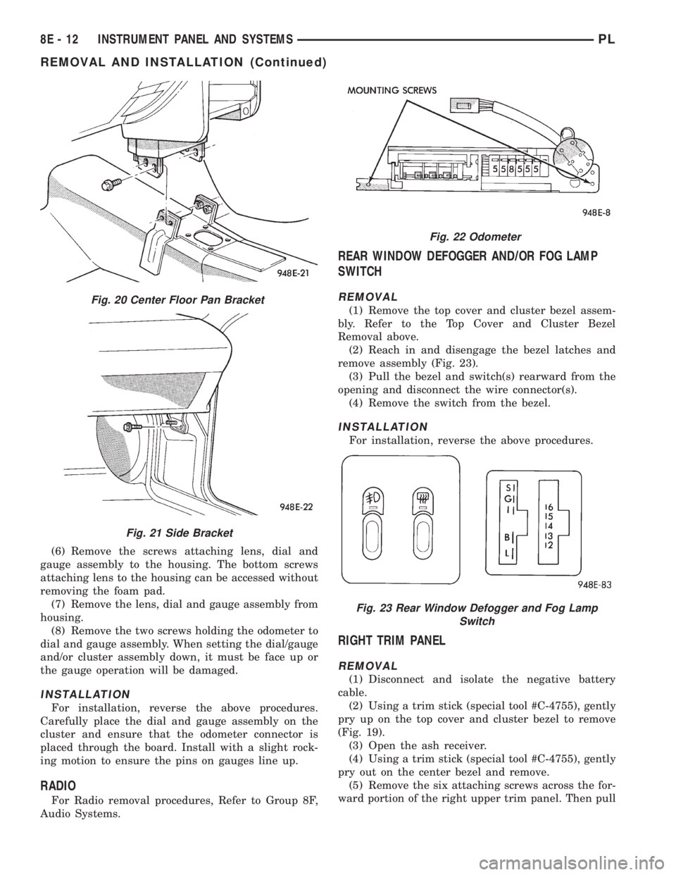
REAR WINDOW DEFOGGER AND/OR FOG LAMP
SWITCH
REMOVAL
(1) Remove the top cover and cluster bezel assem-
bly. Refer to the Top Cover and Cluster Bezel
Removal above.
(2) Reach in and disengage the bezel latches and
remove assembly (Fig. 23).
(3) Pull the bezel and switch(s) rearward from the
opening and disconnect the wire connector(s).
(4) Remove the switch from the bezel.
INSTALLATION
For installation, reverse the above procedures.
RIGHT TRIM PANEL
REMOVAL
(1) Disconnect and isolate the negative battery
cable.
(2) Using a trim stick (special tool #C-4755), gently
pry up on the top cover and cluster bezel to remove
(Fig. 19).
(3) Open the ash receiver.
(4) Using a trim stick (special tool #C-4755), gently
pry out on the center bezel and remove.
(5) Remove the six attaching screws across the for-
ward portion of the right upper trim panel. Then pull
Fig. 20 Center Floor Pan Bracket
Fig. 21 Side Bracket
Fig. 22 Odometer
Fig. 23 Rear Window Defogger and Fog Lamp
Switch
8E - 12 INSTRUMENT PANEL AND SYSTEMSPL
REMOVAL AND INSTALLATION (Continued)
Page 288 of 1200
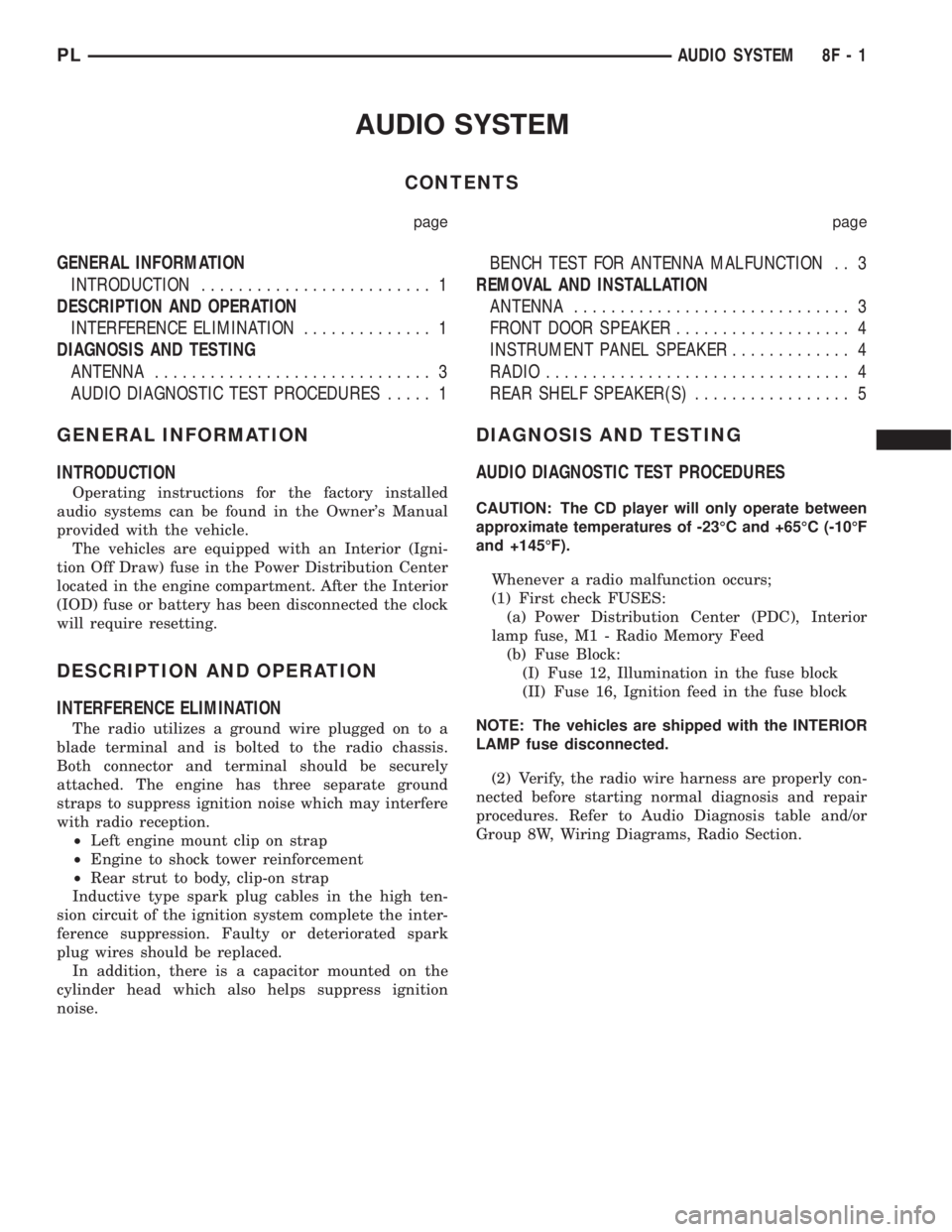
AUDIO SYSTEM
CONTENTS
page page
GENERAL INFORMATION
INTRODUCTION......................... 1
DESCRIPTION AND OPERATION
INTERFERENCE ELIMINATION.............. 1
DIAGNOSIS AND TESTING
ANTENNA.............................. 3
AUDIO DIAGNOSTIC TEST PROCEDURES..... 1BENCH TEST FOR ANTENNA MALFUNCTION . . 3
REMOVAL AND INSTALLATION
ANTENNA.............................. 3
FRONT DOOR SPEAKER................... 4
INSTRUMENT PANEL SPEAKER............. 4
RADIO................................. 4
REAR SHELF SPEAKER(S)................. 5
GENERAL INFORMATION
INTRODUCTION
Operating instructions for the factory installed
audio systems can be found in the Owner's Manual
provided with the vehicle.
The vehicles are equipped with an Interior (Igni-
tion Off Draw) fuse in the Power Distribution Center
located in the engine compartment. After the Interior
(IOD) fuse or battery has been disconnected the clock
will require resetting.
DESCRIPTION AND OPERATION
INTERFERENCE ELIMINATION
The radio utilizes a ground wire plugged on to a
blade terminal and is bolted to the radio chassis.
Both connector and terminal should be securely
attached. The engine has three separate ground
straps to suppress ignition noise which may interfere
with radio reception.
²Left engine mount clip on strap
²Engine to shock tower reinforcement
²Rear strut to body, clip-on strap
Inductive type spark plug cables in the high ten-
sion circuit of the ignition system complete the inter-
ference suppression. Faulty or deteriorated spark
plug wires should be replaced.
In addition, there is a capacitor mounted on the
cylinder head which also helps suppress ignition
noise.
DIAGNOSIS AND TESTING
AUDIO DIAGNOSTIC TEST PROCEDURES
CAUTION: The CD player will only operate between
approximate temperatures of -23ÉC and +65ÉC (-10ÉF
and +145ÉF).
Whenever a radio malfunction occurs;
(1) First check FUSES:
(a) Power Distribution Center (PDC), Interior
lamp fuse, M1 - Radio Memory Feed
(b) Fuse Block:
(I) Fuse 12, Illumination in the fuse block
(II) Fuse 16, Ignition feed in the fuse block
NOTE: The vehicles are shipped with the INTERIOR
LAMP fuse disconnected.
(2) Verify, the radio wire harness are properly con-
nected before starting normal diagnosis and repair
procedures. Refer to Audio Diagnosis table and/or
Group 8W, Wiring Diagrams, Radio Section.
PLAUDIO SYSTEM 8F - 1
Page 289 of 1200
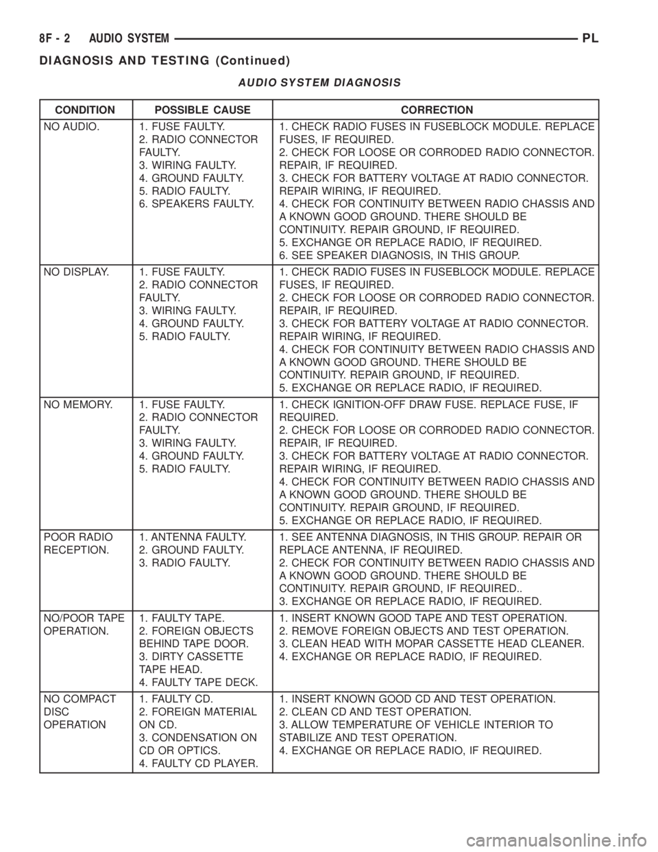
AUDIO SYSTEM DIAGNOSIS
CONDITION POSSIBLE CAUSE CORRECTION
NO AUDIO. 1. FUSE FAULTY.
2. RADIO CONNECTOR
FAULTY.
3. WIRING FAULTY.
4. GROUND FAULTY.
5. RADIO FAULTY.
6. SPEAKERS FAULTY.1. CHECK RADIO FUSES IN FUSEBLOCK MODULE. REPLACE
FUSES, IF REQUIRED.
2. CHECK FOR LOOSE OR CORRODED RADIO CONNECTOR.
REPAIR, IF REQUIRED.
3. CHECK FOR BATTERY VOLTAGE AT RADIO CONNECTOR.
REPAIR WIRING, IF REQUIRED.
4. CHECK FOR CONTINUITY BETWEEN RADIO CHASSIS AND
A KNOWN GOOD GROUND. THERE SHOULD BE
CONTINUITY. REPAIR GROUND, IF REQUIRED.
5. EXCHANGE OR REPLACE RADIO, IF REQUIRED.
6. SEE SPEAKER DIAGNOSIS, IN THIS GROUP.
NO DISPLAY. 1. FUSE FAULTY.
2. RADIO CONNECTOR
FAULTY.
3. WIRING FAULTY.
4. GROUND FAULTY.
5. RADIO FAULTY.1. CHECK RADIO FUSES IN FUSEBLOCK MODULE. REPLACE
FUSES, IF REQUIRED.
2. CHECK FOR LOOSE OR CORRODED RADIO CONNECTOR.
REPAIR, IF REQUIRED.
3. CHECK FOR BATTERY VOLTAGE AT RADIO CONNECTOR.
REPAIR WIRING, IF REQUIRED.
4. CHECK FOR CONTINUITY BETWEEN RADIO CHASSIS AND
A KNOWN GOOD GROUND. THERE SHOULD BE
CONTINUITY. REPAIR GROUND, IF REQUIRED.
5. EXCHANGE OR REPLACE RADIO, IF REQUIRED.
NO MEMORY. 1. FUSE FAULTY.
2. RADIO CONNECTOR
FAULTY.
3. WIRING FAULTY.
4. GROUND FAULTY.
5. RADIO FAULTY.1. CHECK IGNITION-OFF DRAW FUSE. REPLACE FUSE, IF
REQUIRED.
2. CHECK FOR LOOSE OR CORRODED RADIO CONNECTOR.
REPAIR, IF REQUIRED.
3. CHECK FOR BATTERY VOLTAGE AT RADIO CONNECTOR.
REPAIR WIRING, IF REQUIRED.
4. CHECK FOR CONTINUITY BETWEEN RADIO CHASSIS AND
A KNOWN GOOD GROUND. THERE SHOULD BE
CONTINUITY. REPAIR GROUND, IF REQUIRED.
5. EXCHANGE OR REPLACE RADIO, IF REQUIRED.
POOR RADIO
RECEPTION.1. ANTENNA FAULTY.
2. GROUND FAULTY.
3. RADIO FAULTY.1. SEE ANTENNA DIAGNOSIS, IN THIS GROUP. REPAIR OR
REPLACE ANTENNA, IF REQUIRED.
2. CHECK FOR CONTINUITY BETWEEN RADIO CHASSIS AND
A KNOWN GOOD GROUND. THERE SHOULD BE
CONTINUITY. REPAIR GROUND, IF REQUIRED..
3. EXCHANGE OR REPLACE RADIO, IF REQUIRED.
NO/POOR TAPE
OPERATION.1. FAULTY TAPE.
2. FOREIGN OBJECTS
BEHIND TAPE DOOR.
3. DIRTY CASSETTE
TAPE HEAD.
4. FAULTY TAPE DECK.1. INSERT KNOWN GOOD TAPE AND TEST OPERATION.
2. REMOVE FOREIGN OBJECTS AND TEST OPERATION.
3. CLEAN HEAD WITH MOPAR CASSETTE HEAD CLEANER.
4. EXCHANGE OR REPLACE RADIO, IF REQUIRED.
NO COMPACT
DISC
OPERATION1. FAULTY CD.
2. FOREIGN MATERIAL
ON CD.
3. CONDENSATION ON
CD OR OPTICS.
4. FAULTY CD PLAYER.1. INSERT KNOWN GOOD CD AND TEST OPERATION.
2. CLEAN CD AND TEST OPERATION.
3. ALLOW TEMPERATURE OF VEHICLE INTERIOR TO
STABILIZE AND TEST OPERATION.
4. EXCHANGE OR REPLACE RADIO, IF REQUIRED.
8F - 2 AUDIO SYSTEMPL
DIAGNOSIS AND TESTING (Continued)