trunk DODGE NEON 1999 Service Repair Manual
[x] Cancel search | Manufacturer: DODGE, Model Year: 1999, Model line: NEON, Model: DODGE NEON 1999Pages: 1200, PDF Size: 35.29 MB
Page 16 of 1200
PRE-ALIGNMENT VEHICLE INSPECTION
CAUTION: If the front suspension crossmember
shows any sign of impact damage, the steering col-
umn to steering gear coupling must be inspected.
Refer to Group 19 Steering in this service manual
for the inspection procedure.
Before any attempt is made to change or correct
the wheel alignment factors, the following inspection
and necessary corrections must be made on those
parts which influence the steering of the vehicle.
(1) Be sure the fuel tank is full when the wheel
alignment specifications are checked and or adjusted.
A full tank of fuel weighs approximately 75 pounds,
if the fuel tank is not full this reduction in weight
will affect the curb height of the vehicle and the
alignment specifications.
(2) Alignment specifications of a vehicle can be the
most accurately checked and set when the passenger
compartment and trunk of the vehicle are vacant
with the exception of the spare tire. People, luggage,
and any other appreciable weight will adversely
affect the checking and setting of the camber specifi-
cation.
(3) Check and if required, inflate all of the tires to
the recommended air pressure. All tires must be of
the same size and in good condition and have approx-
imately the same tread wear.Note the type of
tread wear on the tire, this will aid in diagnos-
ing problems. Refer to Group 22 Tires And
Wheels in this service manual for the tire wear
diagnosis.
(4) Check the front tire and wheel assemblies for
radial runout.
(5) Before beginning the alignment process,
inspect all suspension component fasteners for loose-
ness and/or loss of specified torque.
(6) Inspect the lower front ball joints and all steer-
ing linkage for looseness and any signs of wear and
or damage.
(7) Inspect the tie rod ends for looseness and any
signs of wear and or damage.
(8) Inspect the rubber bushings on all suspension
components for signs of wear or deterioration. If any
bushings show signs of wear or deterioration they
should be replaced prior to aligning the vehicle.
SERVICE PROCEDURES
WHEEL ALIGNMENT CHECK AND ADJUSTMENT
PROCEDURE
CASTER CAMBER
Front and rear Caster and Camber settings on this
vehicle are determined at the time the vehicle isdesigned, by the location of the vehicle's suspension
components. This is called a Net Build vehicle and
results in no required adjustment of Caster and
Camber after vehicle is built or when servicing the
suspension components. Thus Caster and Camber are
not normally considered an adjustable specification
when performing an alignment on this vehicle.
Though Caster and Camber are not adjustable they
must be checked to ensure they meet vehicle specifi-
cations.
If front and or rear camber is found not to meet
the vehicle alignment specifications, it can be
adjusted using a Mopar Service Kit developed to
allow for camber adjustment. If a vehicle's front or
rear camber is found to be outside the specifications,
the vehicles suspension components should be
inspected for any signs of damage on bending.This
must be done before using the Mopar Service
Kit for setting camber to meet required specifi-
cation.
If a vehicles caster is not within manufacturers
alignment specifications, check for damaged suspen-
sion components or body parts. This type of damage
can cause component locations to move affecting
vehicle alignment.No adjustment can be made
for the Caster setting on this vehicle.
CAUTION: Do not attempt to adjust the vehicles
Caster or Camber by heating, bending or any other
modification of the suspension components.
(1) Correctly position vehicle on alignment rack
and install all required equipment on vehicle, per the
alignment equipment manufacturers specifications.
(2) Center the steering wheel and lock in place
using a steering wheel clamp.
NOTE: Prior to reading each alignment specifica-
tion, jounce the front and rear of the vehicle an
equal number of times. Induce jounce (rear first
then front) by grasping center of bumper and jounc-
ing each end of vehicle an equal number of times.
Bumper should always be released when vehicle is
at the bottom of the jounce cycle.
(3) Correctly jounce vehicle and read front and
rear alignment settings and compare to vehicle spec-
ifications for Camber, Caster and Toe. See Alignment
Specifications in this group of the service manual for
required specifications.If front and rear camber
readings are within required specifications pro-
ceed to step Step 3 in the Front And Rear Toe
Setting procedure. If Camber readings are not
within specifications refer to step Step 1 in the
following camber adjustment bolt package
installation procedure, for the front and rear
Camber adjustment procedure.
PLSUSPENSION 2 - 5
DIAGNOSIS AND TESTING (Continued)
Page 54 of 1200
Inspect the tension strut for signs of contact with
the ground or road debris which has bent or caused
other damage to the tension strut. If the tension
strut is bent or damaged the tension strut will
require replacement.Do not attempt to repair or
straighten a tension strut.
STABILIZER BAR AND BUSHINGS
Inspect the stabilizer bar for damage or bending.
Inspect for broken or distorted stabilizer bar bush-
ings, bushing retainers, and worn or damaged stabi-
lizer bar to strut attaching links. If stabiizer bar to
rear frame rail bushing replacement is required,
bushings can be removed from sway bar by opening
slit and peeling bushing off sway bar.
STABILIZER BAR ATTACHING LINKS
Inspect the bushings and sleeves in the stabilizer
bar attaching links for damage or deterioration.
Inspect the stabilizer bar attaching link to ensure it
is not bent or broken. If any of these conditions are
present when inspecting the attaching links, replace-
ment of the attaching link is required.
SERVICE PROCEDURES
REAR WHEEL ALIGNMENT
Refer to Front And Rear Wheel Toe Setting Proce-
dures in the Wheel Alignment Check And Adjustment
section in this group of the service manual for the
required rear wheel Toe setting procedure.
REMOVAL AND INSTALLATION
STRUT ASSEMBLY
REMOVE
(1) Raise vehicle on jackstands or centered on a
frame contact type hoist. See Hoisting in the Lubri-
cation and Maintenance section of this manual, for
the required lifting procedure to be used for this
vehicle.
(2) Remove the rear wheel and tire assembly from
the vehicle.
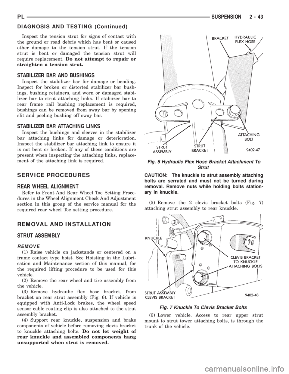
(3) Remove hydraulic flex hose bracket, from
bracket on rear strut assembly (Fig. 6). If vehicle is
equipped with Anti-Lock brakes, the wheel speed
sensor cable routing clip is also attached to the strut
assembly bracket.
(4) Support rear knuckle, suspension and brake
components of vehicle before removing clevis bracket
to knuckle attaching bolts.Do not let weight of
rear knuckle and assembled components hang
unsupported when strut is removed.CAUTION: The knuckle to strut assembly attaching
bolts are serrated and must not be turned during
removal. Remove nuts while holding bolts station-
ary in knuckle.
(5) Remove the 2 clevis bracket bolts (Fig. 7)
attaching strut assembly to rear knuckle.
(6) Lower vehicle. Access to rear upper strut
mount to strut tower attaching bolts, is through the
trunk of the vehicle.
Fig. 6 Hydraulic Flex Hose Bracket Attachment To
Strut
Fig. 7 Knuckle To Clevis Bracket Bolts
PLSUSPENSION 2 - 43
DIAGNOSIS AND TESTING (Continued)
Page 220 of 1200
NOTE: BLACK OR DARK=0to75%state-of-charge
The battery is INADEQUATELY charged and must
be charged until green dot is visible, (12.4 volts or
greater) before the battery is tested or returned to
use. Refer to Causes of Battery Discharging in this
Group for more information.
NOTE: CLEAR COLOR = Replace Battery
WARNING: DO NOT CHARGE, ASSIST BOOST,
LOAD TEST, OR ADD WATER TO THE BATTERY
WHEN CLEAR COLOR DOT IS VISIBLE. PERSONAL
INJURY MAY OCCUR.
A clear color dot shows electrolyte level in battery
is below the test indicator (Fig. 1). Water cannot be
added to a maintenance free battery. The battery
must be replaced. A low electrolyte level may be
caused by an over charging condition. Refer to Gen-
erator Test Procedures on Vehicle.
CAUSES OF BATTERY DISCHARGING
It is normal to have a small 5 to 25 milliamperes
continuous electrical draw from the battery. This
draw will take place with the ignition in the OFF
position, and the courtesy, dome, storage compart-
ments, and engine compartment lights OFF. The con-
tinuous draw is due to various electronic features or
accessories that require electrical current with the
ignition OFF to function properly. When a vehicle is
not used over an extended period of approximately 20
days the IOD fuse should be pulled. The fuse is
located in the power distribution center. removal of
this fuse will reduce the level of battery discharge.
Refer to the Battery Diagnosis and Testing Table for
proper diagnosis.
ABNORMAL BATTERY DISCHARGING
²Corroded battery posts, cables or terminals.
²Loose or worn generator drive belt.
²Electrical loads that exceed the output of the
charging system due to equipment or accessories
installed after delivery.
²Slow driving speeds in heavy traffic conditions
or prolonged idling with high-amperage electrical
systems in use.
²Defective electrical circuit or component causing
excess Ignition Off Draw (IOD). Refer to Battery
Ignition Off Draw (IOD).
²Defective charging system.
²Defective battery.
BATTERY IGNITION OFF DRAW (IOD)
High current draw on the battery with the ignition
OFF will discharge a battery. After a dead battery is
recharged, the vehicle ignition off draw (IOD) shouldbe checked. To determine if a high current draw con-
dition exists first check the vehicle with a test lamp.
(1) Verify that all electrical accessories are OFF.
²Remove key from ignition switch
²Turn off all lights
²Trunk lid is closed
²Engine compartment hood lamp is disconnected
or lamp removed
²Glove box door is closed
²Sun visor vanity lights are OFF
²All doors are closed
²Allow the ignition key lamp system to time out
in approximately 30 seconds, if equipped.
(2) Disconnect battery negative cable (Fig. 4).
(3) Connect a 12 Volt test lamp, with a cold resis-
tance of 5-7 ohms, between the battery negative cable
clamp and the negative post (Fig. 5). If test lamp
goes out system is OK. If test lamp lights and stays
ON, go to Test Lamp Stays ON procedure.
TEST LAMP STAYS ON
There is either a short circuit or a fault in an elec-
tronic module. Two fuses in the Power Distribution
Center (PDC) feed the modules with ignition off
draw.
²Interior lamps fuse (10 Amp) (IOD) PDC.
²Fuel pump fuse (20 Amp) in PDC
(1) Remove interior lamp and fuel pump fuses. By
removing these fuses all ignition off draw from the
vehicle electronics will be disconnected. The test
lamp should go out. If test lamp goes out go to Step
2. If test lamp does not go out there is a current
draw or short circuit. Refer to Group 8W, Wiring Dia-
grams.
(2) Install the fuel pump fuse. If test lamp lights,
there is a current draw or short circuit in the A14
wiring circuit feed.
(a) Disconnect Powertrain Control Module.
(b) If test lamp goes out, replace Powertrain
Control Module.
(c) If test lamp does not go out, there is a cur-
rent draw or short circuit in the A14 circuit feed.
Refer to Group 8W, Wiring Diagrams.
(3) Install the interior lamp fuse. If test lamp
lights, there is a current draw or short circuit in the
M01 circuit. Refer to Group 8W, Wiring Diagrams. If
test lamp stays out, go to Step 4
(4) Use a multi-meter that has at least a range of
200 milliamperes. Install meter between the battery
negative cable and battery negative post (Fig. 6).
Carefully remove the test lamp without disconnecting
the meter. After all modules time-out the total vehi-
cle IOD should be less than 10 milliamperes. If igni-
tion off draw is more than 10 milliamperes go to Step
5.
(5) Remove both fuses from the Power Distribution
Center:
PLBATTERY 8A - 3
DIAGNOSIS AND TESTING (Continued)
Page 270 of 1200
INSTRUMENT PANEL AND SYSTEMS
CONTENTS
page page
GENERAL INFORMATION
INTRODUCTION......................... 1
DESCRIPTION AND OPERATION
DOME LAMP............................ 1
ELECTRONIC DIGITAL CLOCK.............. 1
INSTRUMENT CLUSTER................... 2
WARNING AND INDICATOR LAMPS......... 2
DIAGNOSIS AND TESTING
AIRBAG WARNING SYSTEM............... 2
BRAKE SYSTEM WARNING LAMP TEST...... 2
FOG LAMP SWITCH TEST................. 2
FUEL TANK SENDING UNIT TEST........... 3
HEADLAMP SWITCH TEST................. 3
HEATER A/C BLOWER SWITCH TEST........ 3
HEATER BLOWER SWITCH TEST............ 3
INDIVIDUAL GAUGE INOPERATIVE.......... 4
INSTRUMENT PANEL AND COMPONENTS.... 4
LOW OIL PRESSURE WARNING LAMP TEST . . 4
MULTIPLE GAUGE INOPERATIVE TEST....... 4
SEAT BELT REMINDER SYSTEM TEST....... 6
SENDING UNIT......................... 6
SERVICE ENGINE SOON INDICATOR......... 6
VEHICLE SPEED SENSOR TEST............. 6
REMOVAL AND INSTALLATION
ASH RECEIVER RETAINER AND LAMP....... 6
CENTER BEZEL.......................... 6
CIGAR LIGHTER RECEPTACLE.............. 6
CLUSTER LAMP......................... 7
CLUSTER PRINTED CIRCUIT BOARD........ 7CLUSTER.............................. 7
DOME LENS/LAMP....................... 8
FLOOR CONSOLE........................ 8
GAUGE................................ 8
GLOVE BOX DOOR/BIN................... 8
GLOVE BOX SWITCH/LAMP................ 9
HEADLAMP SWITCH..................... 9
HEATER A/C CONTROL BLOWER SWITCH . . . 10
HEATER A/C CONTROL LAMP............ 10
HEATER A/C CONTROL................... 9
HEATER CONTROL BLOWER SWITCH....... 10
IGNITION KEY LAMP.................... 10
INSTRUMENT PANEL.................... 10
LEFT TRIM PANEL...................... 10
ODOMETER............................ 10
RADIO................................ 12
REAR WINDOW DEFOGGER AND/OR FOG
LAMP SWITCH....................... 12
RIGHT TRIM PANEL..................... 12
SHIFTER KNOB......................... 13
STEERING COLUMN COVER LINER......... 13
STEERING COLUMN COVER.............. 13
STEERING COLUMN SHROUDS............ 13
TOP COVER AND CLUSTER BEZEL
REMOVAL........................... 14
TRANSMISSION RANGE INDICATOR LAMP . . 14
TRUNK LAMP/LENS..................... 14
VEHICLE SPEED SENSOR................ 14
GENERAL INFORMATION
INTRODUCTION
The purpose of the dash gauges and indicator
lamps is to keep the driver informed about the oper-
ating condition of the vehicle. If an abnormal condi-
tion occurs, the driver is informed by indicator lamp.
The driver can seek service before damage occurs.
Indicator lamps use ON/OFF switch functions for
operation, while gauges use a sending unit or sensor.
DESCRIPTION AND OPERATION
DOME LAMP
The Dome Lamp operates when a door is open or
when the headlamp switch is placed in courtesy posi-
tion.
ELECTRONIC DIGITAL CLOCK
The electronic digital clock is in the radio. The
clock and radio each use the display panel built into
the radio. A digital readout indicates the time in
hours and minutes whenever the ignition switch is in
the ON or ACC position.
PLINSTRUMENT PANEL AND SYSTEMS 8E - 1
Page 283 of 1200
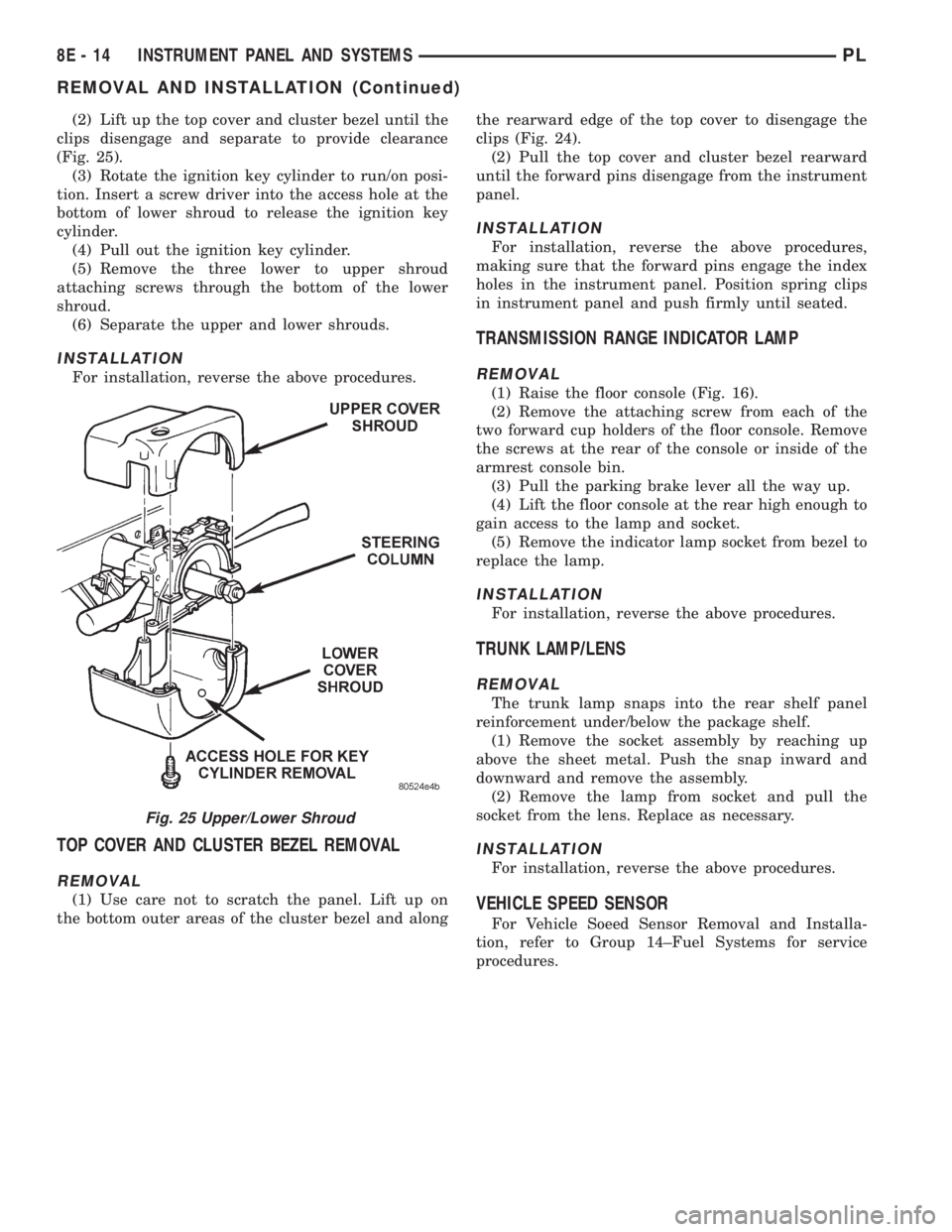
(2) Lift up the top cover and cluster bezel until the
clips disengage and separate to provide clearance
(Fig. 25).
(3) Rotate the ignition key cylinder to run/on posi-
tion. Insert a screw driver into the access hole at the
bottom of lower shroud to release the ignition key
cylinder.
(4) Pull out the ignition key cylinder.
(5) Remove the three lower to upper shroud
attaching screws through the bottom of the lower
shroud.
(6) Separate the upper and lower shrouds.
INSTALLATION
For installation, reverse the above procedures.
TOP COVER AND CLUSTER BEZEL REMOVAL
REMOVAL
(1) Use care not to scratch the panel. Lift up on
the bottom outer areas of the cluster bezel and alongthe rearward edge of the top cover to disengage the
clips (Fig. 24).
(2) Pull the top cover and cluster bezel rearward
until the forward pins disengage from the instrument
panel.
INSTALLATION
For installation, reverse the above procedures,
making sure that the forward pins engage the index
holes in the instrument panel. Position spring clips
in instrument panel and push firmly until seated.
TRANSMISSION RANGE INDICATOR LAMP
REMOVAL
(1) Raise the floor console (Fig. 16).
(2) Remove the attaching screw from each of the
two forward cup holders of the floor console. Remove
the screws at the rear of the console or inside of the
armrest console bin.
(3) Pull the parking brake lever all the way up.
(4) Lift the floor console at the rear high enough to
gain access to the lamp and socket.
(5) Remove the indicator lamp socket from bezel to
replace the lamp.
INSTALLATION
For installation, reverse the above procedures.
TRUNK LAMP/LENS
REMOVAL
The trunk lamp snaps into the rear shelf panel
reinforcement under/below the package shelf.
(1) Remove the socket assembly by reaching up
above the sheet metal. Push the snap inward and
downward and remove the assembly.
(2) Remove the lamp from socket and pull the
socket from the lens. Replace as necessary.
INSTALLATION
For installation, reverse the above procedures.
VEHICLE SPEED SENSOR
For Vehicle Soeed Sensor Removal and Installa-
tion, refer to Group 14±Fuel Systems for service
procedures.
Fig. 25 Upper/Lower Shroud
8E - 14 INSTRUMENT PANEL AND SYSTEMSPL
REMOVAL AND INSTALLATION (Continued)
Page 336 of 1200
FRONT SIDE MARKER LAMP BULB
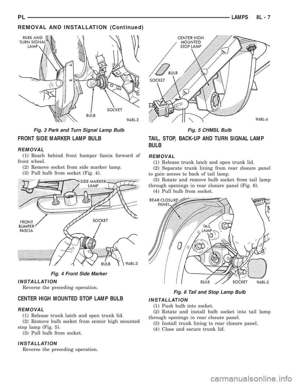
REMOVAL
(1) Reach behind front bumper fascia forward of
front wheel.
(2) Remove socket from side marker lamp.
(3) Pull bulb from socket (Fig. 4).
INSTALLATION
Reverse the preceding operation.
CENTER HIGH MOUNTED STOP LAMP BULB
REMOVAL
(1) Release trunk latch and open trunk lid.
(2) Remove bulb socket from center high mounted
stop lamp (Fig. 5).
(3) Pull bulb from socket.
INSTALLATION
Reverse the preceding operation.
TAIL, STOP, BACK-UP AND TURN SIGNAL LAMP
BULB
REMOVAL
(1) Release trunk latch and open trunk lid.
(2) Separate trunk lining from rear closure panel
to gain access to back of tail lamp.
(3) Rotate and remove bulb socket from tail lamp
through openings in rear closure panel (Fig. 6).
(4) Pull bulb from socket.
INSTALLATION
(1) Push bulb into socket.
(2) Rotate and install bulb socket into tail lamp
through openings in rear closure panel.
(3) Install trunk lining to rear closure panel.
(4) Close and secure trunk lid.
Fig. 3 Park and Turn Signal Lamp Bulb
Fig. 4 Front Side Marker
Fig. 5 CHMSL Bulb
Fig. 6 Tail and Stop Lamp Bulb
PLLAMPS 8L - 7
REMOVAL AND INSTALLATION (Continued)
Page 337 of 1200
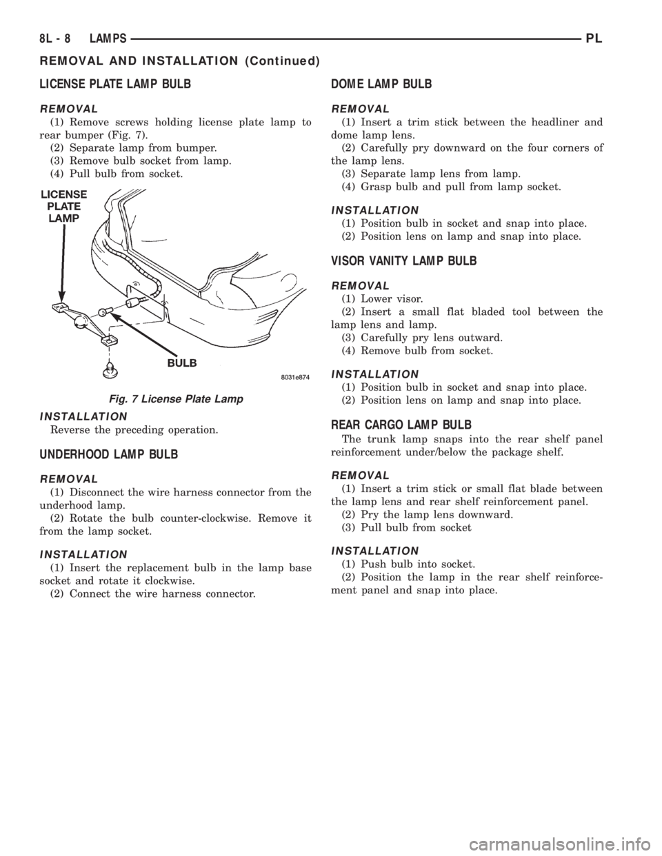
LICENSE PLATE LAMP BULB
REMOVAL
(1) Remove screws holding license plate lamp to
rear bumper (Fig. 7).
(2) Separate lamp from bumper.
(3) Remove bulb socket from lamp.
(4) Pull bulb from socket.
INSTALLATION
Reverse the preceding operation.
UNDERHOOD LAMP BULB
REMOVAL
(1) Disconnect the wire harness connector from the
underhood lamp.
(2) Rotate the bulb counter-clockwise. Remove it
from the lamp socket.
INSTALLATION
(1) Insert the replacement bulb in the lamp base
socket and rotate it clockwise.
(2) Connect the wire harness connector.
DOME LAMP BULB
REMOVAL
(1) Insert a trim stick between the headliner and
dome lamp lens.
(2) Carefully pry downward on the four corners of
the lamp lens.
(3) Separate lamp lens from lamp.
(4) Grasp bulb and pull from lamp socket.
INSTALLATION
(1) Position bulb in socket and snap into place.
(2) Position lens on lamp and snap into place.
VISOR VANITY LAMP BULB
REMOVAL
(1) Lower visor.
(2) Insert a small flat bladed tool between the
lamp lens and lamp.
(3) Carefully pry lens outward.
(4) Remove bulb from socket.
INSTALLATION
(1) Position bulb in socket and snap into place.
(2) Position lens on lamp and snap into place.
REAR CARGO LAMP BULB
The trunk lamp snaps into the rear shelf panel
reinforcement under/below the package shelf.
REMOVAL
(1) Insert a trim stick or small flat blade between
the lamp lens and rear shelf reinforcement panel.
(2) Pry the lamp lens downward.
(3) Pull bulb from socket
INSTALLATION
(1) Push bulb into socket.
(2) Position the lamp in the rear shelf reinforce-
ment panel and snap into place.
Fig. 7 License Plate Lamp
8L - 8 LAMPSPL
REMOVAL AND INSTALLATION (Continued)
Page 339 of 1200
INSTALLATION
Reverse the preceding operation.
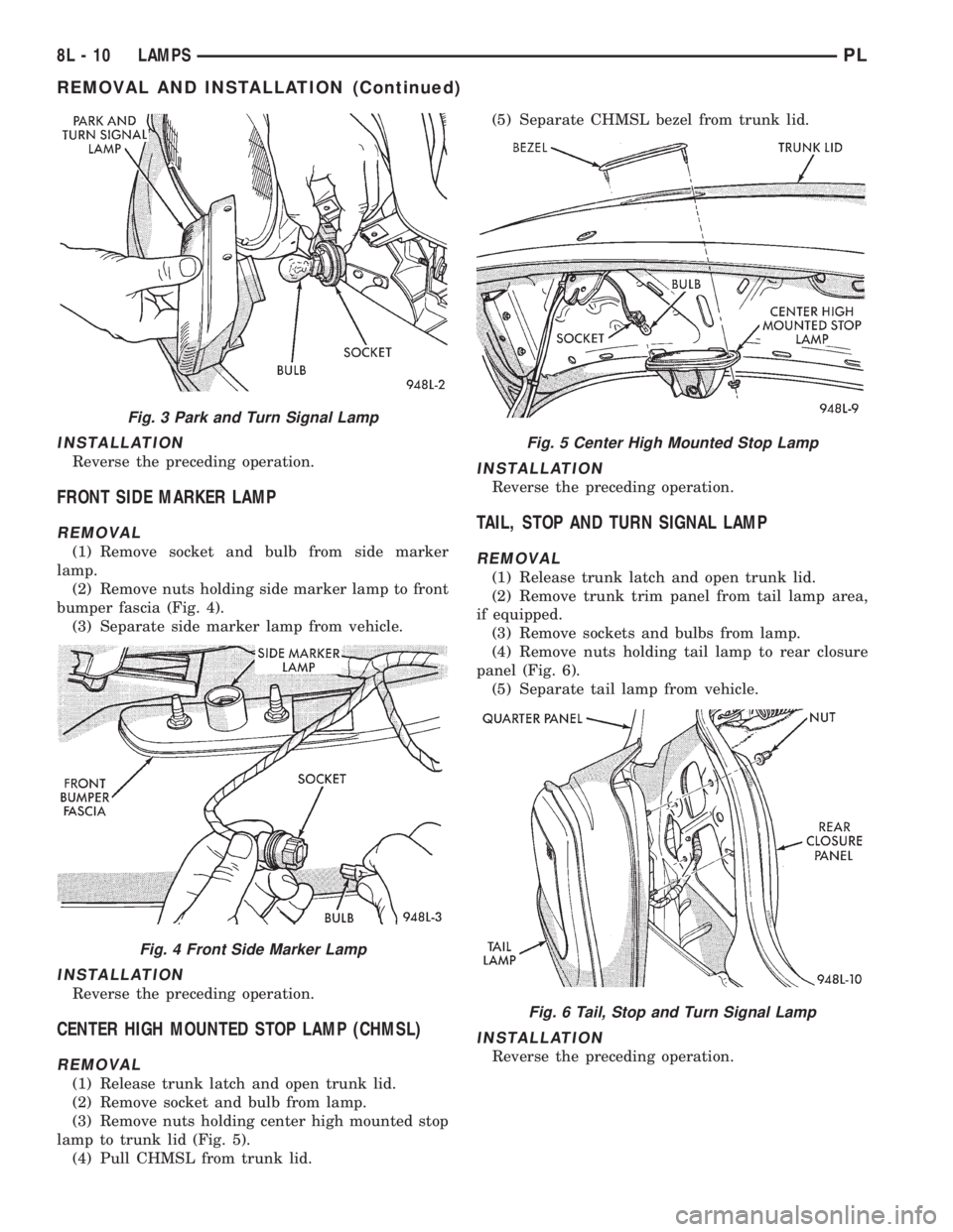
FRONT SIDE MARKER LAMP
REMOVAL
(1) Remove socket and bulb from side marker
lamp.
(2) Remove nuts holding side marker lamp to front
bumper fascia (Fig. 4).
(3) Separate side marker lamp from vehicle.
INSTALLATION
Reverse the preceding operation.
CENTER HIGH MOUNTED STOP LAMP (CHMSL)
REMOVAL
(1) Release trunk latch and open trunk lid.
(2) Remove socket and bulb from lamp.
(3) Remove nuts holding center high mounted stop
lamp to trunk lid (Fig. 5).
(4) Pull CHMSL from trunk lid.(5) Separate CHMSL bezel from trunk lid.
INSTALLATION
Reverse the preceding operation.
TAIL, STOP AND TURN SIGNAL LAMP
REMOVAL
(1) Release trunk latch and open trunk lid.
(2) Remove trunk trim panel from tail lamp area,
if equipped.
(3) Remove sockets and bulbs from lamp.
(4) Remove nuts holding tail lamp to rear closure
panel (Fig. 6).
(5) Separate tail lamp from vehicle.
INSTALLATION
Reverse the preceding operation.
Fig. 3 Park and Turn Signal Lamp
Fig. 4 Front Side Marker Lamp
Fig. 5 Center High Mounted Stop Lamp
Fig. 6 Tail, Stop and Turn Signal Lamp
8L - 10 LAMPSPL
REMOVAL AND INSTALLATION (Continued)
Page 411 of 1200
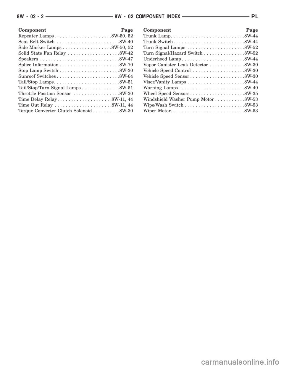
Component Page
Repeater Lamps.....................8W-50, 52
Seat Belt Switch.......................8W-40
Side Marker Lamps..................8W-50, 52
Solid State Fan Relay...................8W-42
Speakers.............................8W-47
Splice Information......................8W-70
Stop Lamp Switch......................8W-30
Sunroof Switches.......................8W-64
Tail/Stop Lamps........................8W-51
Tail/Stop/Turn Signal Lamps..............8W-51
Throttle Position Sensor.................8W-30
Time Delay Relay....................8W-11,44
Time Out Relay.....................8W-11,44
Torque Converter Clutch Solenoid..........8W-30Component Page
Trunk Lamp...........................8W-44
Trunk Switch..........................8W-44
Turn Signal Lamps.....................8W-52
Turn Signal/Hazard Switch...............8W-52
Underhood Lamp.......................8W-44
Vapor Canister Leak Detector.............8W-30
Vehicle Speed Control...................8W-30
Vehicle Speed Sensor....................8W-30
Visor/Vanity Lamps.....................8W-44
Warning Lamps........................8W-40
Wheel Speed Sensors....................8W-35
Windshield Washer Pump Motor...........8W-53
Wipe/Wash Switch......................8W-53
Wiper Motor...........................8W-53
8W - 02 - 2 8W - 02 COMPONENT INDEXPL
Page 412 of 1200
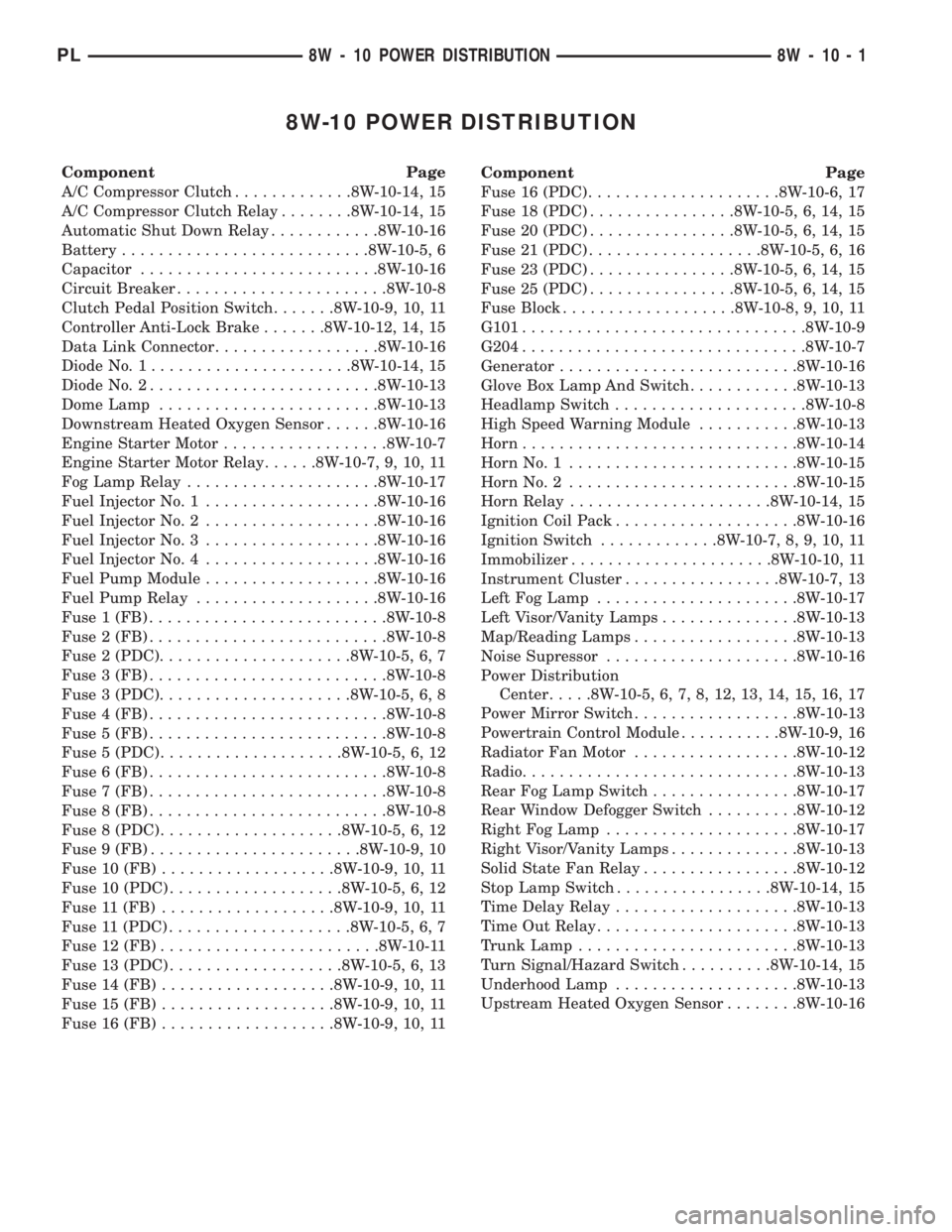
8W-10 POWER DISTRIBUTION
Component Page
A/C Compressor Clutch.............8W-10-14, 15
A/C Compressor Clutch Relay........8W-10-14, 15
Automatic Shut Down Relay............8W-10-16
Battery...........................8W-10-5, 6
Capacitor..........................8W-10-16
Circuit Breaker.......................8W-10-8
Clutch Pedal Position Switch.......8W-10-9, 10, 11
Controller Anti-Lock Brake.......8W-10-12, 14, 15
Data Link Connector..................8W-10-16
Diode No. 1......................8W-10-14, 15
Diode No. 2.........................8W-10-13
Dome Lamp........................8W-10-13
Downstream Heated Oxygen Sensor......8W-10-16
Engine Starter Motor..................8W-10-7
Engine Starter Motor Relay......8W-10-7, 9, 10, 11
Fog Lamp Relay.....................8W-10-17
Fuel Injector No. 1...................8W-10-16
Fuel Injector No. 2...................8W-10-16
Fuel Injector No. 3...................8W-10-16
Fuel Injector No. 4...................8W-10-16
Fuel Pump Module...................8W-10-16
Fuel Pump Relay....................8W-10-16
Fuse 1 (FB)..........................8W-10-8
Fuse 2 (FB)..........................8W-10-8
Fuse 2 (PDC).....................8W-10-5, 6, 7
Fuse 3 (FB)..........................8W-10-8
Fuse 3 (PDC).....................8W-10-5, 6, 8
Fuse 4 (FB)..........................8W-10-8
Fuse 5 (FB)..........................8W-10-8
Fuse 5 (PDC)....................8W-10-5, 6, 12
Fuse 6 (FB)..........................8W-10-8
Fuse 7 (FB)..........................8W-10-8
Fuse 8 (FB)..........................8W-10-8
Fuse 8 (PDC)....................8W-10-5, 6, 12
Fuse 9 (FB).......................8W-10-9, 10
Fuse 10 (FB)...................8W-10-9, 10, 11
Fuse 10 (PDC)...................8W-10-5, 6, 12
Fuse 11 (FB)...................8W-10-9, 10, 11
Fuse 11 (PDC)....................8W-10-5, 6, 7
Fuse 12 (FB)........................8W-10-11
Fuse 13 (PDC)...................8W-10-5, 6, 13
Fuse 14 (FB)...................8W-10-9, 10, 11
Fuse 15 (FB)...................8W-10-9, 10, 11
Fuse 16 (FB)...................8W-10-9, 10, 11Component Page
Fuse 16 (PDC).....................8W-10-6, 17
Fuse 18 (PDC)................8W-10-5, 6, 14, 15
Fuse 20 (PDC)................8W-10-5, 6, 14, 15
Fuse 21 (PDC)...................8W-10-5, 6, 16
Fuse 23 (PDC)................8W-10-5, 6, 14, 15
Fuse 25 (PDC)................8W-10-5, 6, 14, 15
Fuse Block...................8W-10-8, 9, 10, 11
G101...............................8W-10-9
G204...............................8W-10-7
Generator..........................8W-10-16
Glove Box Lamp And Switch............8W-10-13
Headlamp Switch.....................8W-10-8
High Speed Warning Module...........8W-10-13
Horn..............................8W-10-14
Horn No. 1.........................8W-10-15
Horn No. 2.........................8W-10-15
Horn Relay......................8W-10-14, 15
Ignition Coil Pack....................8W-10-16
Ignition Switch.............8W-10-7, 8, 9, 10, 11
Immobilizer......................8W-10-10, 11
Instrument Cluster.................8W-10-7, 13
Left Fog Lamp......................8W-10-17
Left Visor/Vanity Lamps...............8W-10-13
Map/Reading Lamps..................8W-10-13
Noise Supressor.....................8W-10-16
Power Distribution
Center.....8W-10-5, 6, 7, 8, 12, 13, 14, 15, 16, 17
Power Mirror Switch..................8W-10-13
Powertrain Control Module...........8W-10-9, 16
Radiator Fan Motor..................8W-10-12
Radio..............................8W-10-13
Rear Fog Lamp Switch................8W-10-17
Rear Window Defogger Switch..........8W-10-12
Right Fog Lamp.....................8W-10-17
Right Visor/Vanity Lamps..............8W-10-13
Solid State Fan Relay.................8W-10-12
Stop Lamp Switch.................8W-10-14, 15
Time Delay Relay....................8W-10-13
Time Out Relay......................8W-10-13
Trunk Lamp........................8W-10-13
Turn Signal/Hazard Switch..........8W-10-14, 15
Underhood Lamp....................8W-10-13
Upstream Heated Oxygen Sensor........8W-10-16
PL8W - 10 POWER DISTRIBUTION 8W - 10 - 1