trunk release DODGE NEON 1999 Service Repair Manual
[x] Cancel search | Manufacturer: DODGE, Model Year: 1999, Model line: NEON, Model: DODGE NEON 1999Pages: 1200, PDF Size: 35.29 MB
Page 16 of 1200
PRE-ALIGNMENT VEHICLE INSPECTION
CAUTION: If the front suspension crossmember
shows any sign of impact damage, the steering col-
umn to steering gear coupling must be inspected.
Refer to Group 19 Steering in this service manual
for the inspection procedure.
Before any attempt is made to change or correct
the wheel alignment factors, the following inspection
and necessary corrections must be made on those
parts which influence the steering of the vehicle.
(1) Be sure the fuel tank is full when the wheel
alignment specifications are checked and or adjusted.
A full tank of fuel weighs approximately 75 pounds,
if the fuel tank is not full this reduction in weight
will affect the curb height of the vehicle and the
alignment specifications.
(2) Alignment specifications of a vehicle can be the
most accurately checked and set when the passenger
compartment and trunk of the vehicle are vacant
with the exception of the spare tire. People, luggage,
and any other appreciable weight will adversely
affect the checking and setting of the camber specifi-
cation.
(3) Check and if required, inflate all of the tires to
the recommended air pressure. All tires must be of
the same size and in good condition and have approx-
imately the same tread wear.Note the type of
tread wear on the tire, this will aid in diagnos-
ing problems. Refer to Group 22 Tires And
Wheels in this service manual for the tire wear
diagnosis.
(4) Check the front tire and wheel assemblies for
radial runout.
(5) Before beginning the alignment process,
inspect all suspension component fasteners for loose-
ness and/or loss of specified torque.
(6) Inspect the lower front ball joints and all steer-
ing linkage for looseness and any signs of wear and
or damage.
(7) Inspect the tie rod ends for looseness and any
signs of wear and or damage.
(8) Inspect the rubber bushings on all suspension
components for signs of wear or deterioration. If any
bushings show signs of wear or deterioration they
should be replaced prior to aligning the vehicle.
SERVICE PROCEDURES
WHEEL ALIGNMENT CHECK AND ADJUSTMENT
PROCEDURE
CASTER CAMBER
Front and rear Caster and Camber settings on this
vehicle are determined at the time the vehicle isdesigned, by the location of the vehicle's suspension
components. This is called a Net Build vehicle and
results in no required adjustment of Caster and
Camber after vehicle is built or when servicing the
suspension components. Thus Caster and Camber are
not normally considered an adjustable specification
when performing an alignment on this vehicle.
Though Caster and Camber are not adjustable they
must be checked to ensure they meet vehicle specifi-
cations.
If front and or rear camber is found not to meet
the vehicle alignment specifications, it can be
adjusted using a Mopar Service Kit developed to
allow for camber adjustment. If a vehicle's front or
rear camber is found to be outside the specifications,
the vehicles suspension components should be
inspected for any signs of damage on bending.This
must be done before using the Mopar Service
Kit for setting camber to meet required specifi-
cation.
If a vehicles caster is not within manufacturers
alignment specifications, check for damaged suspen-
sion components or body parts. This type of damage
can cause component locations to move affecting
vehicle alignment.No adjustment can be made
for the Caster setting on this vehicle.
CAUTION: Do not attempt to adjust the vehicles
Caster or Camber by heating, bending or any other
modification of the suspension components.
(1) Correctly position vehicle on alignment rack
and install all required equipment on vehicle, per the
alignment equipment manufacturers specifications.
(2) Center the steering wheel and lock in place
using a steering wheel clamp.
NOTE: Prior to reading each alignment specifica-
tion, jounce the front and rear of the vehicle an
equal number of times. Induce jounce (rear first
then front) by grasping center of bumper and jounc-
ing each end of vehicle an equal number of times.
Bumper should always be released when vehicle is
at the bottom of the jounce cycle.
(3) Correctly jounce vehicle and read front and
rear alignment settings and compare to vehicle spec-
ifications for Camber, Caster and Toe. See Alignment
Specifications in this group of the service manual for
required specifications.If front and rear camber
readings are within required specifications pro-
ceed to step Step 3 in the Front And Rear Toe
Setting procedure. If Camber readings are not
within specifications refer to step Step 1 in the
following camber adjustment bolt package
installation procedure, for the front and rear
Camber adjustment procedure.
PLSUSPENSION 2 - 5
DIAGNOSIS AND TESTING (Continued)
Page 283 of 1200
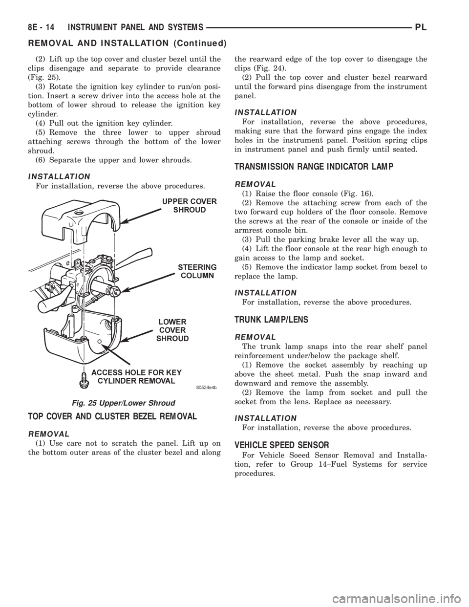
(2) Lift up the top cover and cluster bezel until the
clips disengage and separate to provide clearance
(Fig. 25).
(3) Rotate the ignition key cylinder to run/on posi-
tion. Insert a screw driver into the access hole at the
bottom of lower shroud to release the ignition key
cylinder.
(4) Pull out the ignition key cylinder.
(5) Remove the three lower to upper shroud
attaching screws through the bottom of the lower
shroud.
(6) Separate the upper and lower shrouds.
INSTALLATION
For installation, reverse the above procedures.
TOP COVER AND CLUSTER BEZEL REMOVAL
REMOVAL
(1) Use care not to scratch the panel. Lift up on
the bottom outer areas of the cluster bezel and alongthe rearward edge of the top cover to disengage the
clips (Fig. 24).
(2) Pull the top cover and cluster bezel rearward
until the forward pins disengage from the instrument
panel.
INSTALLATION
For installation, reverse the above procedures,
making sure that the forward pins engage the index
holes in the instrument panel. Position spring clips
in instrument panel and push firmly until seated.
TRANSMISSION RANGE INDICATOR LAMP
REMOVAL
(1) Raise the floor console (Fig. 16).
(2) Remove the attaching screw from each of the
two forward cup holders of the floor console. Remove
the screws at the rear of the console or inside of the
armrest console bin.
(3) Pull the parking brake lever all the way up.
(4) Lift the floor console at the rear high enough to
gain access to the lamp and socket.
(5) Remove the indicator lamp socket from bezel to
replace the lamp.
INSTALLATION
For installation, reverse the above procedures.
TRUNK LAMP/LENS
REMOVAL
The trunk lamp snaps into the rear shelf panel
reinforcement under/below the package shelf.
(1) Remove the socket assembly by reaching up
above the sheet metal. Push the snap inward and
downward and remove the assembly.
(2) Remove the lamp from socket and pull the
socket from the lens. Replace as necessary.
INSTALLATION
For installation, reverse the above procedures.
VEHICLE SPEED SENSOR
For Vehicle Soeed Sensor Removal and Installa-
tion, refer to Group 14±Fuel Systems for service
procedures.
Fig. 25 Upper/Lower Shroud
8E - 14 INSTRUMENT PANEL AND SYSTEMSPL
REMOVAL AND INSTALLATION (Continued)
Page 336 of 1200
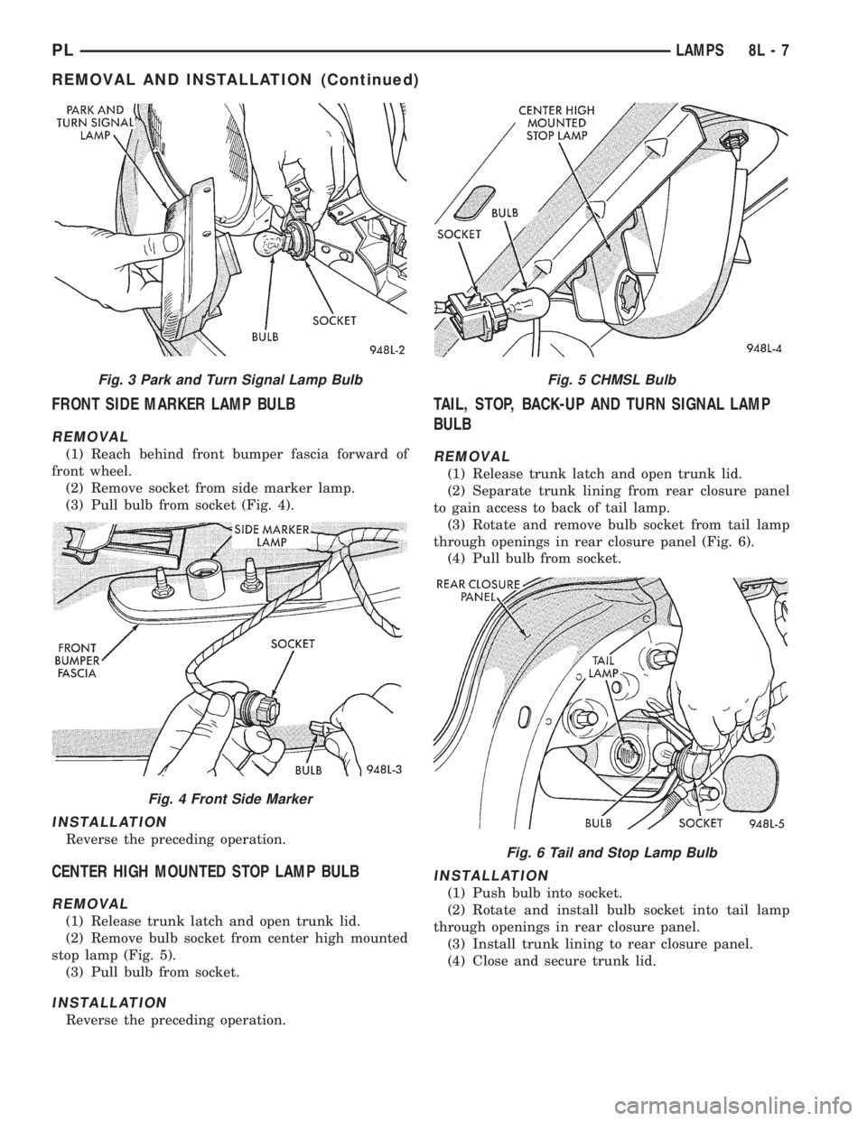
FRONT SIDE MARKER LAMP BULB
REMOVAL
(1) Reach behind front bumper fascia forward of
front wheel.
(2) Remove socket from side marker lamp.
(3) Pull bulb from socket (Fig. 4).
INSTALLATION
Reverse the preceding operation.
CENTER HIGH MOUNTED STOP LAMP BULB
REMOVAL
(1) Release trunk latch and open trunk lid.
(2) Remove bulb socket from center high mounted
stop lamp (Fig. 5).
(3) Pull bulb from socket.
INSTALLATION
Reverse the preceding operation.
TAIL, STOP, BACK-UP AND TURN SIGNAL LAMP
BULB
REMOVAL
(1) Release trunk latch and open trunk lid.
(2) Separate trunk lining from rear closure panel
to gain access to back of tail lamp.
(3) Rotate and remove bulb socket from tail lamp
through openings in rear closure panel (Fig. 6).
(4) Pull bulb from socket.
INSTALLATION
(1) Push bulb into socket.
(2) Rotate and install bulb socket into tail lamp
through openings in rear closure panel.
(3) Install trunk lining to rear closure panel.
(4) Close and secure trunk lid.
Fig. 3 Park and Turn Signal Lamp Bulb
Fig. 4 Front Side Marker
Fig. 5 CHMSL Bulb
Fig. 6 Tail and Stop Lamp Bulb
PLLAMPS 8L - 7
REMOVAL AND INSTALLATION (Continued)
Page 339 of 1200
INSTALLATION
Reverse the preceding operation.
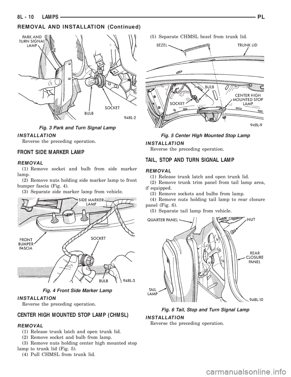
FRONT SIDE MARKER LAMP
REMOVAL
(1) Remove socket and bulb from side marker
lamp.
(2) Remove nuts holding side marker lamp to front
bumper fascia (Fig. 4).
(3) Separate side marker lamp from vehicle.
INSTALLATION
Reverse the preceding operation.
CENTER HIGH MOUNTED STOP LAMP (CHMSL)
REMOVAL
(1) Release trunk latch and open trunk lid.
(2) Remove socket and bulb from lamp.
(3) Remove nuts holding center high mounted stop
lamp to trunk lid (Fig. 5).
(4) Pull CHMSL from trunk lid.(5) Separate CHMSL bezel from trunk lid.
INSTALLATION
Reverse the preceding operation.
TAIL, STOP AND TURN SIGNAL LAMP
REMOVAL
(1) Release trunk latch and open trunk lid.
(2) Remove trunk trim panel from tail lamp area,
if equipped.
(3) Remove sockets and bulbs from lamp.
(4) Remove nuts holding tail lamp to rear closure
panel (Fig. 6).
(5) Separate tail lamp from vehicle.
INSTALLATION
Reverse the preceding operation.
Fig. 3 Park and Turn Signal Lamp
Fig. 4 Front Side Marker Lamp
Fig. 5 Center High Mounted Stop Lamp
Fig. 6 Tail, Stop and Turn Signal Lamp
8L - 10 LAMPSPL
REMOVAL AND INSTALLATION (Continued)
Page 830 of 1200
FRAME AND BUMPERS
CONTENTS
page page
BUMPERS............................... 1FRAMES................................ 3
BUMPERS
INDEX
page page
REMOVAL AND INSTALLATION
FRONT BUMPER FASCIA.................. 1
FRONT BUMPER REINFORCEMENT.......... 1REAR BUMPER FASCIA................... 1
REAR BUMPER REINFORCEMENT........... 2
REMOVAL AND INSTALLATION
FRONT BUMPER FASCIA
REMOVAL
(1) Remove nuts holding front bumper fascia
bracket to bottom of fender forward of front wheels.
(2) Remove screws holding front fascia to inner
wheelhouse.
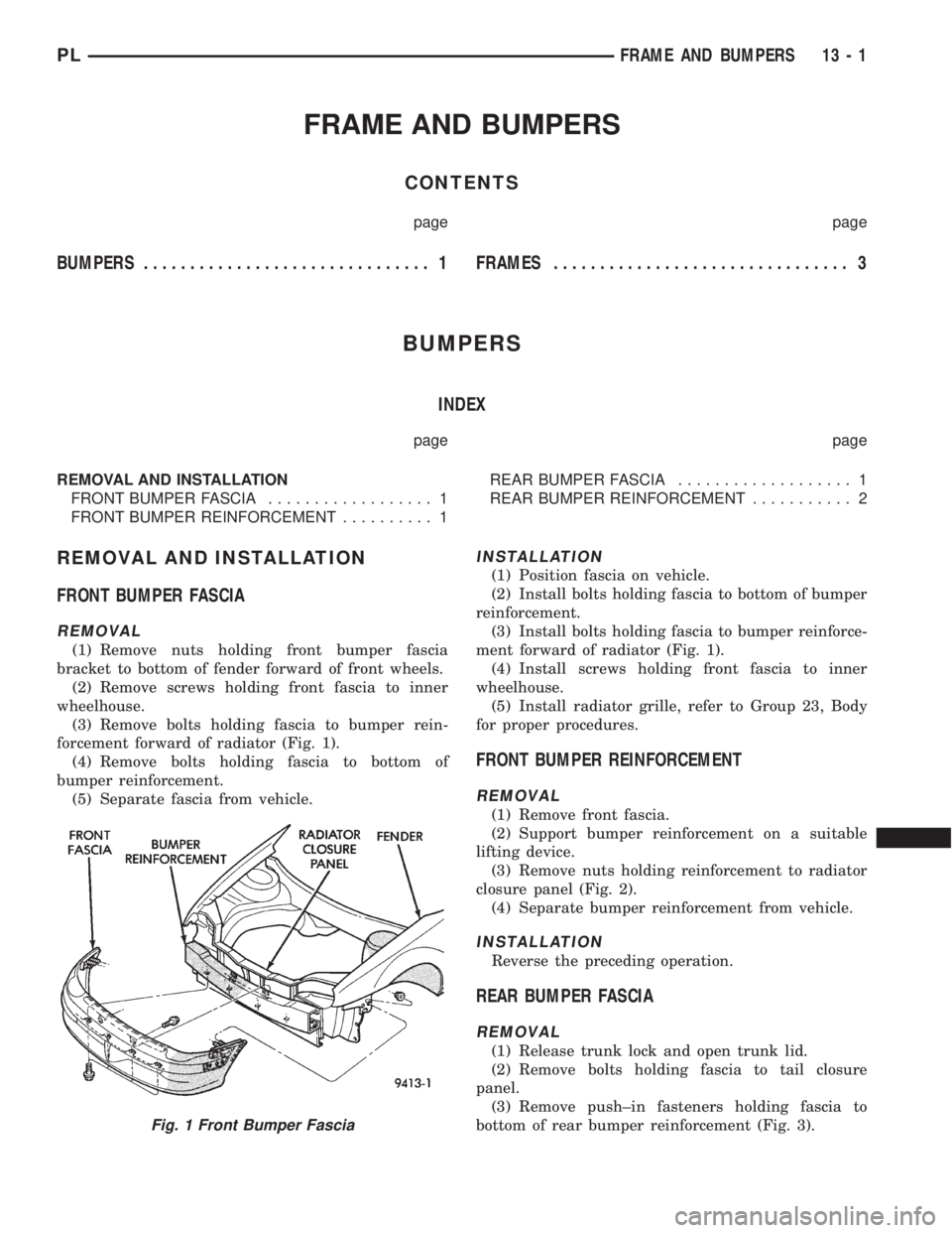
(3) Remove bolts holding fascia to bumper rein-
forcement forward of radiator (Fig. 1).
(4) Remove bolts holding fascia to bottom of
bumper reinforcement.
(5) Separate fascia from vehicle.
INSTALLATION
(1) Position fascia on vehicle.
(2) Install bolts holding fascia to bottom of bumper
reinforcement.
(3) Install bolts holding fascia to bumper reinforce-
ment forward of radiator (Fig. 1).
(4) Install screws holding front fascia to inner
wheelhouse.
(5) Install radiator grille, refer to Group 23, Body
for proper procedures.
FRONT BUMPER REINFORCEMENT
REMOVAL
(1) Remove front fascia.
(2) Support bumper reinforcement on a suitable
lifting device.
(3) Remove nuts holding reinforcement to radiator
closure panel (Fig. 2).
(4) Separate bumper reinforcement from vehicle.
INSTALLATION
Reverse the preceding operation.
REAR BUMPER FASCIA
REMOVAL
(1) Release trunk lock and open trunk lid.
(2) Remove bolts holding fascia to tail closure
panel.
(3) Remove push±in fasteners holding fascia to
bottom of rear bumper reinforcement (Fig. 3).
Fig. 1 Front Bumper Fascia
PLFRAME AND BUMPERS 13 - 1
Page 1083 of 1200
BODY COMPONENTS
INDEX
page page
DIAGNOSIS AND TESTING
WATER LEAKS.......................... 3
WIND NOISE............................ 4
SERVICE PROCEDURES
HEAT STAKING.......................... 4
REMOVAL AND INSTALLATION
WINDOW REGULATORÐ4 DOOR........... 36
A-PILLAR TRIM.......................... 4
B-PILLAR APPLIQUEÐ2 DOOR.............. 5
B-PILLAR APPLIQUEÐ4 DOOR.............. 5
B-PILLAR TRIMÐ4 DOOR.................. 6
B-PILLAR WEATHERSTRIP CHANNEL......... 6
BODY VENT............................. 6
CARPET............................... 7
CHILD RESTRAINT SEAT BACK............. 8
CHILD SEAT MODULE..................... 8
COWL COVER........................... 7
DOOR HINGE........................... 9
DOOR LOCK CYLINDER.................. 10
DOOR OPENING TRIM WELT.............. 10
DOOR SILL TRIM........................ 10
DOOR................................. 9
FLOOR CONSOLE LATCH................. 11
FLOOR CONSOLE....................... 11
FRONT DOOR CHECK STOP............... 11
FRONT DOOR GLASSÐ2 DOOR............ 12
FRONT DOOR GLASSÐ4 DOOR............ 13
FRONT DOOR INNER BELT WEATHERSTRIP . . 13
FRONT DOOR LATCH STRIKER............ 14
FRONT DOOR LATCH.................... 13
FRONT DOOR OUTER BELT WEATHERSTRIP . 14
FRONT DOOR OUTSIDE HANDLE........... 14
FRONT DOOR TRIM PANEL................ 14
FRONT DOOR WATER SHIELD............. 16
FRONT DOOR WEATHERSTRIP............ 16
FRONT OUTBOARD SEAT BELT............ 17
FRONT SEAT BELT BUCKLE............... 18
FRONT SEAT BELT RETRACTOR........... 18
FRONT SEAT........................... 17
FRONT SHOULDER BELT ADJUSTER........ 18
FRONT VERTICAL GUIDE BAR............. 18
GRILLE............................... 19
HEADLINING........................... 19
HOOD HINGE.......................... 20
HOOD LATCH.......................... 21
HOOD RELEASE CABLE.................. 21
HOOD................................ 20
LOCK BUTTON BELL-CRANK.............. 21
LOWER QUARTER TRIMÐ4 DOOR.......... 22PARCEL SHELF TRIM.................... 22
QUARTER TRIM PANELÐ2 DOOR........... 22
REAR DOOR GLASS..................... 23
REAR DOOR INNER BELT WEATHERSTRIP . . . 23
REAR DOOR INTERLOCK LATCH STRIKER . . . 24
REAR DOOR LATCH STRIKER............. 24
REAR DOOR LATCH..................... 24
REAR DOOR LOCK BELL CRANK........... 24
REAR DOOR OUTER BELT WEATHERSTRIP . . 25
REAR DOOR TRIM....................... 25
REAR DOOR WINDOW REGULATOR........ 25
REAR SEAT BACK....................... 26
REAR SEAT BELT BUCKLE................ 26
REAR SEAT BELT RETRACTOR............ 26
REAR SEAT CUSHION.................... 26
REAR SPOILER......................... 27
REAR VERTICAL GUIDE BAR.............. 27
ROOF APERTURE (RAP) MOLDING.......... 28
ROOF RACK CROSS RAILS............... 28
ROOF RACK........................... 28
ROOF RAIL WEATHER-STRIP FOUR DOOR . . . 29
ROOF RAIL WEATHER-STRIP ± TWO DOOR . . . 29
SIDE COWL TRIM....................... 30
SIDE VIEW MIRROR STANCHION........... 31
SIDE VIEW MIRROR TRIM COVER.......... 31
SIDE VIEW MIRROR..................... 30
SUN VISOR SUPPORT................... 31
SUN VISOR............................ 31
TRUNK CARPET........................ 31
TRUNK LATCH STRIKER.................. 32
TRUNK LATCH.......................... 32
TRUNK LID LIFT SPRINGS................ 33
TRUNK LID............................ 32
TRUNK LOCK CYLINDER................. 33
TRUNK TRIM PANEL..................... 34
TRUNK WEATHERSTRIP.................. 34
UPPER QUARTER TRIMÐ4 DOOR.......... 34
WINDOW INNERBELT STABILIZER.......... 34
WINDOW REGULATORÐ2 DOOR........... 35
ADJUSTMENTS
FRONT DOOR GLASS ADJUSTMENT........ 37
FRONT DOOR LATCH ADJUSTMENT........ 38
REAR DOOR GLASS ADJUSTMENT......... 38
REAR DOOR LATCH ADJUSTMENT.......... 39
SPECIFICATIONS
BODY LUBRICATION SPECIFICATIONS....... 39
SPECIAL TOOLS
BODY................................. 40
23 - 2 BODYPL
Page 1088 of 1200
CARPET
REMOVAL
(1) Remove front seats.
(2) Remove rear seat cushion.
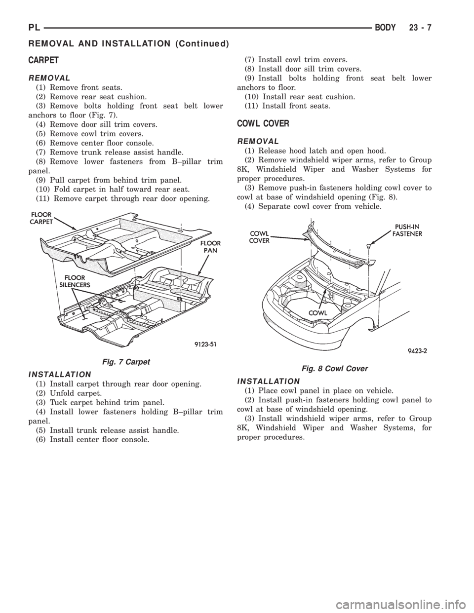
(3) Remove bolts holding front seat belt lower
anchors to floor (Fig. 7).
(4) Remove door sill trim covers.
(5) Remove cowl trim covers.
(6) Remove center floor console.
(7) Remove trunk release assist handle.
(8) Remove lower fasteners from B±pillar trim
panel.
(9) Pull carpet from behind trim panel.
(10) Fold carpet in half toward rear seat.
(11) Remove carpet through rear door opening.
INSTALLATION
(1) Install carpet through rear door opening.
(2) Unfold carpet.
(3) Tuck carpet behind trim panel.
(4) Install lower fasteners holding B±pillar trim
panel.
(5) Install trunk release assist handle.
(6) Install center floor console.(7) Install cowl trim covers.
(8) Install door sill trim covers.
(9) Install bolts holding front seat belt lower
anchors to floor.
(10) Install rear seat cushion.
(11) Install front seats.
COWL COVER
REMOVAL
(1) Release hood latch and open hood.
(2) Remove windshield wiper arms, refer to Group
8K, Windshield Wiper and Washer Systems for
proper procedures.
(3) Remove push-in fasteners holding cowl cover to
cowl at base of windshield opening (Fig. 8).
(4) Separate cowl cover from vehicle.
INSTALLATION
(1) Place cowl panel in place on vehicle.
(2) Install push-in fasteners holding cowl panel to
cowl at base of windshield opening.
(3) Install windshield wiper arms, refer to Group
8K, Windshield Wiper and Washer Systems, for
proper procedures.
Fig. 7 CarpetFig. 8 Cowl Cover
PLBODY 23 - 7
REMOVAL AND INSTALLATION (Continued)
Page 1108 of 1200
(2) Position inboard seat belts on top of seat cush-
ion.
(3) Guide seat cushion loops into retainer cups in
floor pan.
(4) Push downward on the front corners of the seat
cushion to engage retainers.
REAR SPOILER
REMOVAL
(1) Release trunk latch and open trunk lid.
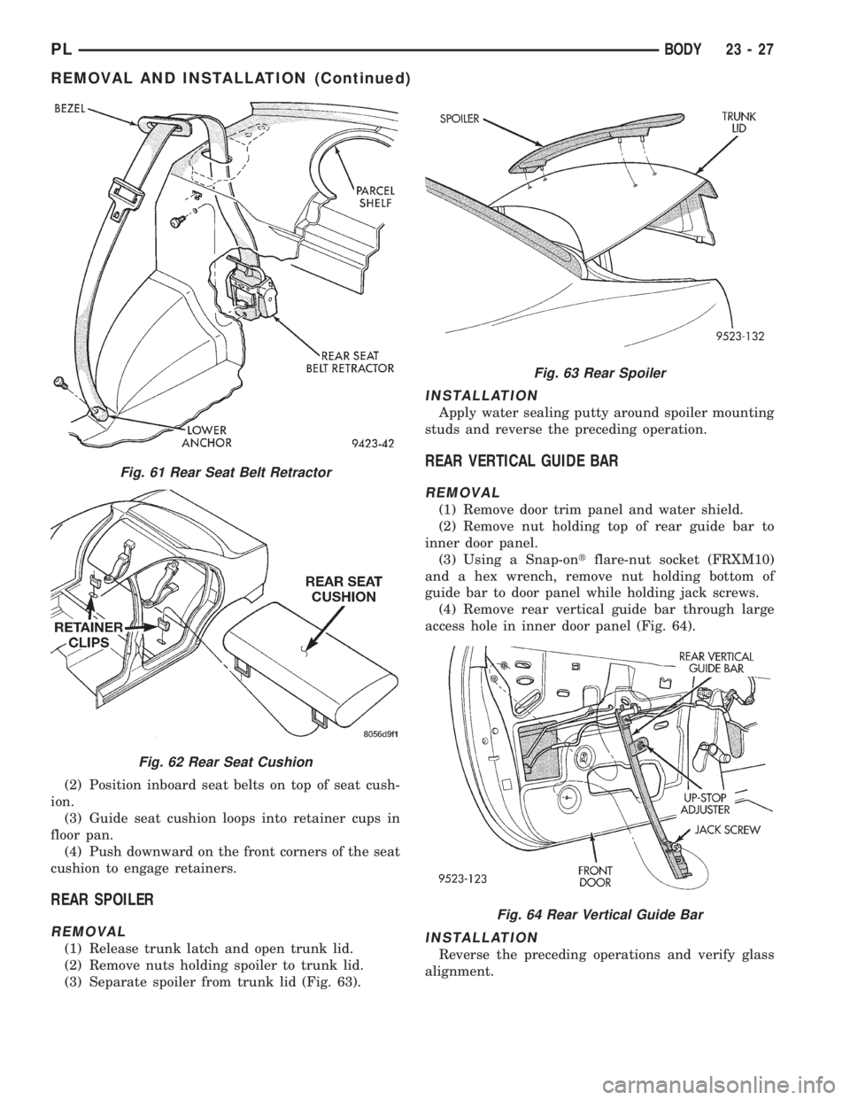
(2) Remove nuts holding spoiler to trunk lid.
(3) Separate spoiler from trunk lid (Fig. 63).
INSTALLATION
Apply water sealing putty around spoiler mounting
studs and reverse the preceding operation.
REAR VERTICAL GUIDE BAR
REMOVAL
(1) Remove door trim panel and water shield.
(2) Remove nut holding top of rear guide bar to
inner door panel.
(3) Using a Snap-ontflare-nut socket (FRXM10)
and a hex wrench, remove nut holding bottom of
guide bar to door panel while holding jack screws.
(4) Remove rear vertical guide bar through large
access hole in inner door panel (Fig. 64).
INSTALLATION
Reverse the preceding operations and verify glass
alignment.
Fig. 61 Rear Seat Belt Retractor
Fig. 62 Rear Seat Cushion
Fig. 63 Rear Spoiler
Fig. 64 Rear Vertical Guide Bar
PLBODY 23 - 27
REMOVAL AND INSTALLATION (Continued)
Page 1113 of 1200
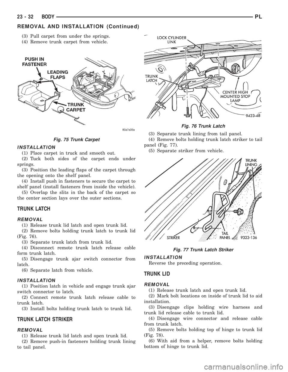
(3) Pull carpet from under the springs.
(4) Remove trunk carpet from vehicle.
INSTALLATION
(1) Place carpet in truck and smooth out.
(2) Tuck both sides of the carpet ends under
springs.
(3) Position the leading flaps of the carpet through
the opening onto the shelf panel.
(4) Install push in fasteners to secure the carpet to
shelf panel (install fasteners from inside the vehicle).
(5) Overlap the slits in the back of the carpet so
the center section lays over the outer sections.
TRUNK LATCH
REMOVAL
(1) Release trunk lid latch and open trunk lid.
(2) Remove bolts holding trunk latch to trunk lid
(Fig. 76).
(3) Separate trunk latch from trunk lid.
(4) Disconnect remote trunk latch release cable
form trunk latch.
(5) Disengage trunk ajar switch connector from
latch.
(6) Separate latch from vehicle.
INSTALLATION
(1) Position latch in vehicle and engage trunk ajar
switch connector to latch.
(2) Connect remote trunk latch release cable to
trunk latch.
(3) Install bolts holding trunk latch to trunk lid.
TRUNK LATCH STRIKER
REMOVAL
(1) Release trunk lid latch and open trunk lid.
(2) Remove push-in fasteners holding trunk lining
to tail panel.(3) Separate trunk lining from tail panel.
(4) Remove bolts holding trunk latch striker to tail
panel (Fig. 77).
(5) Separate striker from vehicle.
INSTALLATION
Reverse the preceding operation.
TRUNK LID
REMOVAL
(1) Release trunk latch and open trunk lid.
(2) Mark bolt locations on inside of trunk lid to aid
installation.
(3) Disengage clips holding wire harness and
trunk lid release cable to trunk lid.
(4) Disengage wire connector and release cable
from trunk latch.
(5) Remove bolts holding top of hinge to trunk lid
(Fig. 78).
(6) With aid from a helper, remove bolts holding
bottom of hinge to trunk lid.
Fig. 75 Trunk Carpet
Fig. 76 Trunk Latch
Fig. 77 Trunk Latch Striker
23 - 32 BODYPL
REMOVAL AND INSTALLATION (Continued)
Page 1114 of 1200
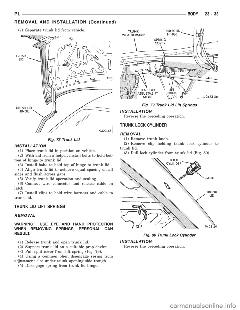
(7) Separate trunk lid from vehicle.
INSTALLATION
(1) Place trunk lid in position on vehicle.
(2) With aid from a helper, install bolts to hold bot-
tom of hinge to trunk lid.
(3) Install bolts to hold top of hinge to trunk lid.
(4) Align trunk lid to achieve equal spacing on all
sides and flush across gaps.
(5) Verify trunk lid operation and sealing.
(6) Connect wire connector and release cable on
latch.
(7) Install clips to hold wire harness and cable to
trunk lid.
TRUNK LID LIFT SPRINGS
REMOVAL
WARNING: USE EYE AND HAND PROTECTION
WHEN REMOVING SPRINGS, PERSONAL CAN
RESULT.
(1) Release trunk and open trunk lid.
(2) Support trunk lid on a suitable prop device.
(3) Pull split cover from lift spring (Fig. 79).
(4) Using a common plier, disengage spring from
adjustment slot under trunk opening side trough.
(5) Disengage spring from trunk lid hinge.
INSTALLATION
Reverse the preceding operation.
TRUNK LOCK CYLINDER
REMOVAL
(1) Remove trunk latch.
(2) Remove clip holding trunk lock cylinder to
trunk lid.
(3) Pull lock cylinder from trunk lid (Fig. 80).
INSTALLATION
Reverse the preceding operation.
Fig. 78 Trunk Lid
Fig. 79 Trunk Lid Lift Springs
Fig. 80 Trunk Lock Cylinder
PLBODY 23 - 33
REMOVAL AND INSTALLATION (Continued)