fuel filter location DODGE NEON 1999 Service Repair Manual
[x] Cancel search | Manufacturer: DODGE, Model Year: 1999, Model line: NEON, Model: DODGE NEON 1999Pages: 1200, PDF Size: 35.29 MB
Page 715 of 1200

assure gasket rails are flat. Flatten rails with a ham-
mer on a heavy steel plate if required. Gasket sur-
faces must be free of oil and dirt. Make sure old
gasket material is removed from blind attaching
holes.
FORM-IN-PLACE GASKET APPLICATION
Assembling parts using a form-in-place gasket
requires care but it's easier then using precut gas-
kets.
MopartGasket Maker material should be applied
sparingly 1 mm (0.040 inch.) diameter or less of seal-
ant to one gasket surface. Be certain the material
surrounds each mounting hole. Excess material can
easily be wiped off. Components should be torqued in
place within 15 minutes. The use of a locating dowel
is recommended during assembly to prevent smear-
ing material off the location.
The MopartSilicone Rubber Adhesive Sealant gas-
ket material or equivalent should be applied in a con-
tinuous bead approximately 3 mm (0.120 inch) in
diameter. All mounting holes must be circled. For
corner sealing, a 3.17 or 6.35 mm (1/8 or 1/4 inch.)
drop is placed in the center of the gasket contact
area. Uncured sealant may be removed with a shop
towel. Components should be torqued in place while
the sealant is still wet to the touch (within 10 min-
utes). The usage of a locating dowel is recommended
during assembly to prevent smearing material off the
location.
CRANKSHAFT SPROCKET BOLT ACCESS PLUG
An Access plug is located in the right inner fender
shield. Remove the plug and insert the proper size
socket, extension and ratchet, when crankshaft rota-
tion is necessary.
ENGINE CORE PLUGS
REMOVAL
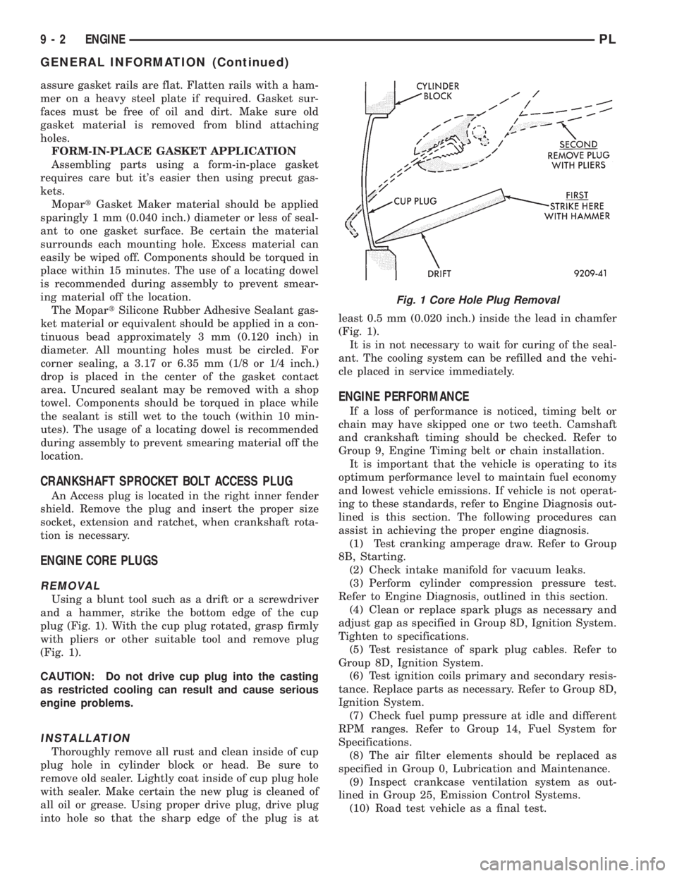
Using a blunt tool such as a drift or a screwdriver
and a hammer, strike the bottom edge of the cup
plug (Fig. 1). With the cup plug rotated, grasp firmly
with pliers or other suitable tool and remove plug
(Fig. 1).
CAUTION: Do not drive cup plug into the casting
as restricted cooling can result and cause serious
engine problems.
INSTALLATION
Thoroughly remove all rust and clean inside of cup
plug hole in cylinder block or head. Be sure to
remove old sealer. Lightly coat inside of cup plug hole
with sealer. Make certain the new plug is cleaned of
all oil or grease. Using proper drive plug, drive plug
into hole so that the sharp edge of the plug is atleast 0.5 mm (0.020 inch.) inside the lead in chamfer
(Fig. 1).
It is in not necessary to wait for curing of the seal-
ant. The cooling system can be refilled and the vehi-
cle placed in service immediately.
ENGINE PERFORMANCE
If a loss of performance is noticed, timing belt or
chain may have skipped one or two teeth. Camshaft
and crankshaft timing should be checked. Refer to
Group 9, Engine Timing belt or chain installation.
It is important that the vehicle is operating to its
optimum performance level to maintain fuel economy
and lowest vehicle emissions. If vehicle is not operat-
ing to these standards, refer to Engine Diagnosis out-
lined is this section. The following procedures can
assist in achieving the proper engine diagnosis.
(1) Test cranking amperage draw. Refer to Group
8B, Starting.
(2) Check intake manifold for vacuum leaks.
(3) Perform cylinder compression pressure test.
Refer to Engine Diagnosis, outlined in this section.
(4) Clean or replace spark plugs as necessary and
adjust gap as specified in Group 8D, Ignition System.
Tighten to specifications.
(5) Test resistance of spark plug cables. Refer to
Group 8D, Ignition System.
(6) Test ignition coils primary and secondary resis-
tance. Replace parts as necessary. Refer to Group 8D,
Ignition System.
(7) Check fuel pump pressure at idle and different
RPM ranges. Refer to Group 14, Fuel System for
Specifications.
(8) The air filter elements should be replaced as
specified in Group 0, Lubrication and Maintenance.
(9) Inspect crankcase ventilation system as out-
lined in Group 25, Emission Control Systems.
(10) Road test vehicle as a final test.
Fig. 1 Core Hole Plug Removal
9 - 2 ENGINEPL
GENERAL INFORMATION (Continued)
Page 718 of 1200

(2) Remove negative battery cable.
(3) Place a shop towel around the spark plugs
when removing them from the engine. This will catch
any fluid that may possibly be in the cylinder under
pressure.
(4) With all spark plugs removed, rotate engine
crankshaft using a breaker bar and socket.
(5) Identify the fluid in the cylinder(s) (i.e., cool-
ant, fuel, oil or other).
(6) Make sure all fluid has been removed from the
cylinders. Inspect engine for damage (i.e., Connecting
Rods, Pistons, Valves etc.)
(7) Repair engine or components as necessary to
prevent this problem from occurring again.
CAUTION: Squirt approximately 1 teaspoon of oil
into cylinders, rotate engine to lubricate the cylin-
der walls to prevent damage on restart.
(8) Install new spark plugs.
(9) Drain engine oil and remove oil filter.
(10) Fill engine with specified amount of approved
oil and install new oil filter.
(11) Connect negative battery cable.
(12) Start engine and check for any leaks.
CHECKING ENGINE OIL LEVEL
The best time to check engine oil level is after it
has sat overnight, or if the engine has been running,
allow the engine to be shut off for at least 5 minutes
before checking oil level.
Checking the oil while the vehicle is on level
ground will improve the accuracy of the oil level
reading. Add only when the level is at or below the
ADD mark (Fig. 5).
ENGINE OIL SERVICE
WARNING: NEW OR USED ENGINE OIL CAN BE
IRRITATING TO THE SKIN. AVOID PROLONGED OR
REPEATED SKIN CONTACT WITH ENGINE OIL.
CONTAMINANTS IN USED ENGINE OIL, CAUSED BY
INTERNAL COMBUSTION, CAN BE HAZARDOUS TO
YOUR HEALTH. THOROUGHLY WASH EXPOSED
SKIN WITH SOAP AND WATER. DO NOT WASH
SKIN WITH GASOLINE, DIESEL FUEL, THINNER, OR
SOLVENTS, HEALTH PROBLEMS CAN RESULT. DO
NOT POLLUTE, DISPOSE OF USED ENGINE OIL
PROPERLY. CONTACT YOUR DEALER OR GOVERN-MENT AGENCY FOR LOCATION OF COLLECTION
CENTER IN YOUR AREA.
ENGINE OIL SPECIFICATION
CAUTION: Do not use non-detergent or straight
mineral oil when adding or changing crankcase
lubricant. Engine failure can result.
API SERVICE GRADE CERTIFIED
Use an engine oil that is API Service Grade Certi-
fied. MOPARtprovides engine oils that conforms to
this service grade.
SAE VISCOSITY
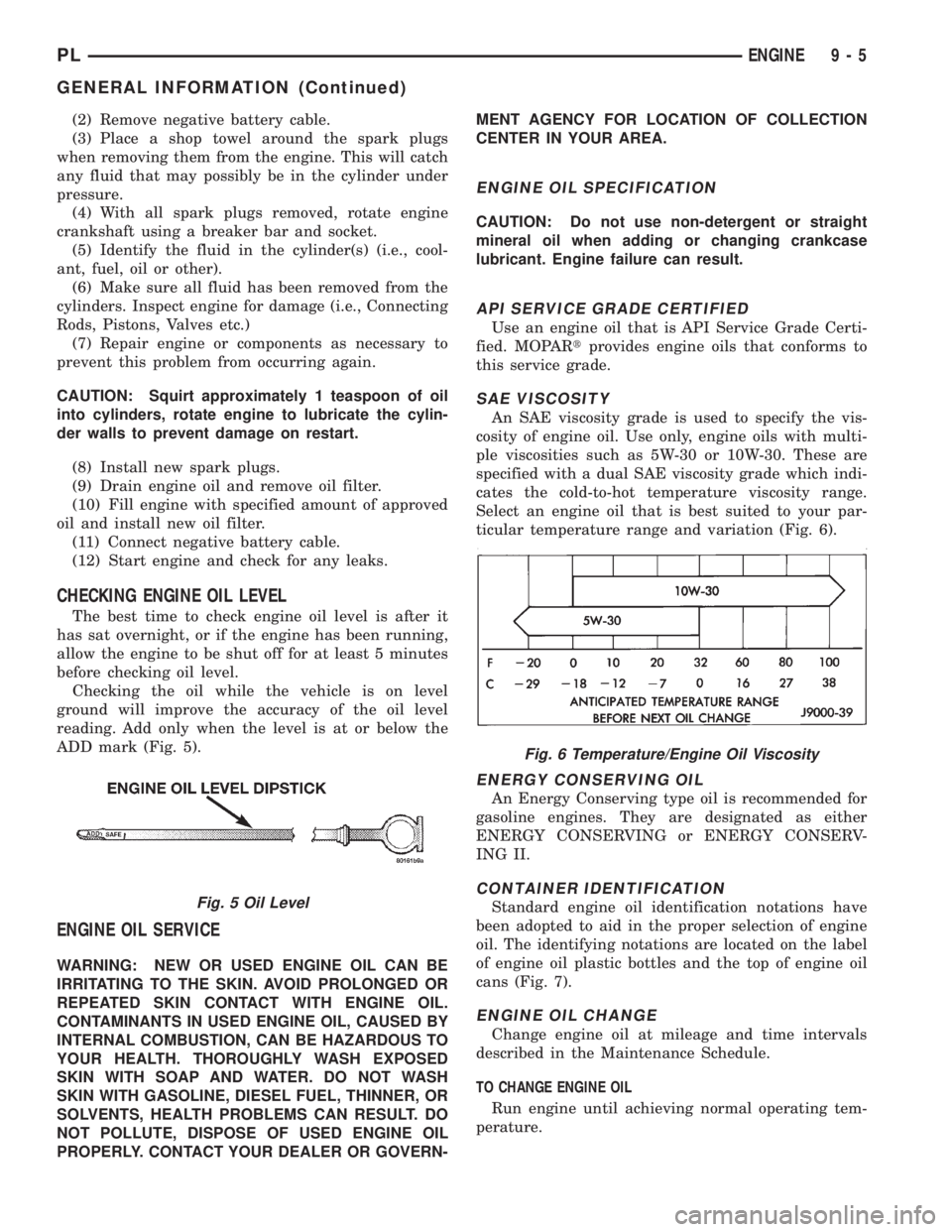
An SAE viscosity grade is used to specify the vis-
cosity of engine oil. Use only, engine oils with multi-
ple viscosities such as 5W-30 or 10W-30. These are
specified with a dual SAE viscosity grade which indi-
cates the cold-to-hot temperature viscosity range.
Select an engine oil that is best suited to your par-
ticular temperature range and variation (Fig. 6).
ENERGY CONSERVING OIL
An Energy Conserving type oil is recommended for
gasoline engines. They are designated as either
ENERGY CONSERVING or ENERGY CONSERV-
ING II.
CONTAINER IDENTIFICATION
Standard engine oil identification notations have
been adopted to aid in the proper selection of engine
oil. The identifying notations are located on the label
of engine oil plastic bottles and the top of engine oil
cans (Fig. 7).
ENGINE OIL CHANGE
Change engine oil at mileage and time intervals
described in the Maintenance Schedule.
TO CHANGE ENGINE OIL
Run engine until achieving normal operating tem-
perature.
Fig. 5 Oil Level
Fig. 6 Temperature/Engine Oil Viscosity
PLENGINE 9 - 5
GENERAL INFORMATION (Continued)