fuse box DODGE NEON 2000 Service Repair Manual
[x] Cancel search | Manufacturer: DODGE, Model Year: 2000, Model line: NEON, Model: DODGE NEON 2000Pages: 1285, PDF Size: 29.42 MB
Page 214 of 1285
be checked. To determine if a high current draw con-
dition exists first check the vehicle with a test lamp.
(1) Verify that all electrical accessories are OFF.
²Remove key from ignition switch
²Turn off all lights
²Trunk lid is closed
²Engine compartment hood lamp is disconnected
or lamp removed
²Map lamp on rear view mirror
²Glove box door is closed
²Sun visor vanity lights are OFF
²All doors are closed
²Allow the ignition key lamp system to time out
in approximately 30 seconds, if equipped.
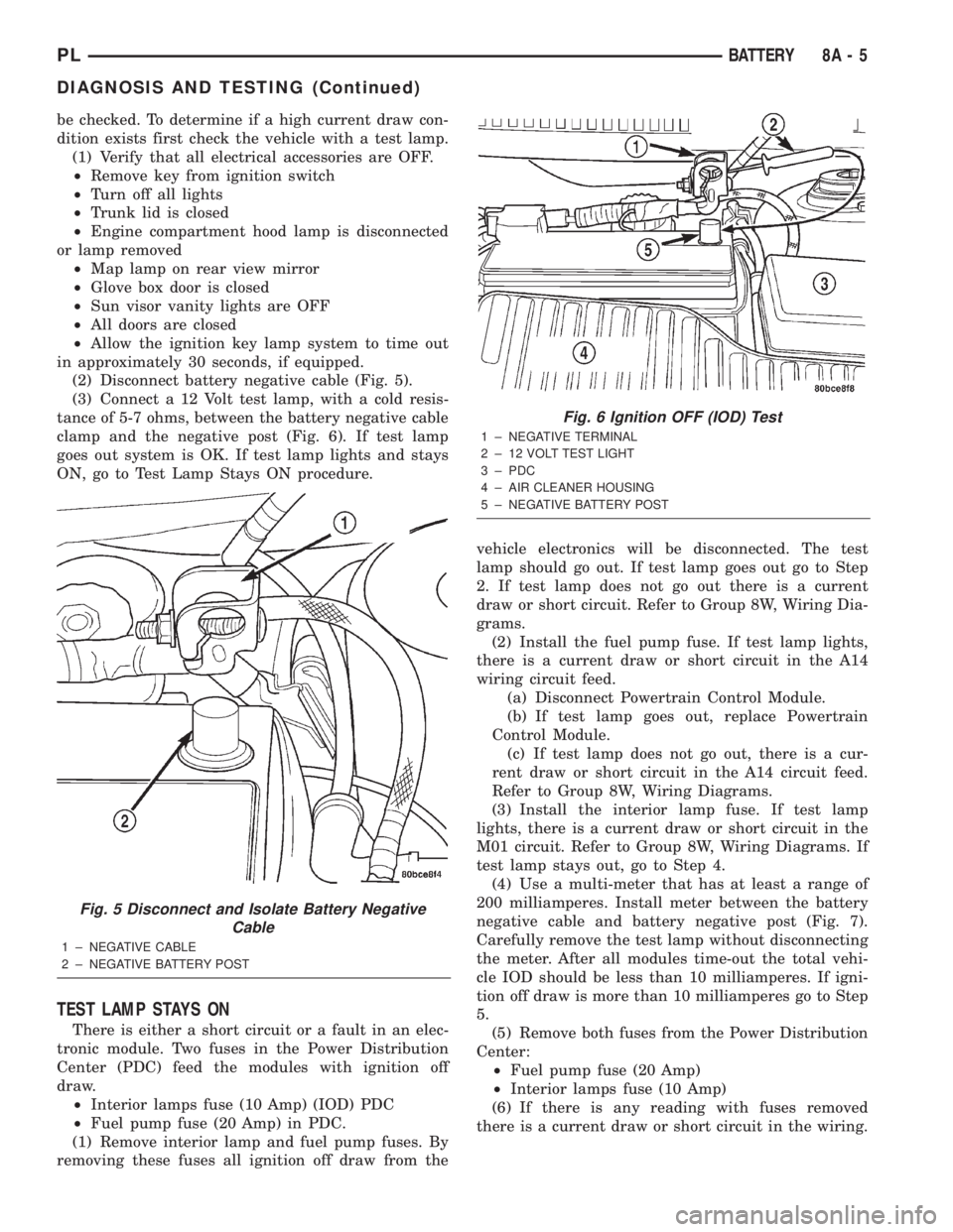
(2) Disconnect battery negative cable (Fig. 5).
(3) Connect a 12 Volt test lamp, with a cold resis-
tance of 5-7 ohms, between the battery negative cable
clamp and the negative post (Fig. 6). If test lamp
goes out system is OK. If test lamp lights and stays
ON, go to Test Lamp Stays ON procedure.
TEST LAMP STAYS ON
There is either a short circuit or a fault in an elec-
tronic module. Two fuses in the Power Distribution
Center (PDC) feed the modules with ignition off
draw.
²Interior lamps fuse (10 Amp) (IOD) PDC
²Fuel pump fuse (20 Amp) in PDC.
(1) Remove interior lamp and fuel pump fuses. By
removing these fuses all ignition off draw from thevehicle electronics will be disconnected. The test
lamp should go out. If test lamp goes out go to Step
2. If test lamp does not go out there is a current
draw or short circuit. Refer to Group 8W, Wiring Dia-
grams.
(2) Install the fuel pump fuse. If test lamp lights,
there is a current draw or short circuit in the A14
wiring circuit feed.
(a) Disconnect Powertrain Control Module.
(b) If test lamp goes out, replace Powertrain
Control Module.
(c) If test lamp does not go out, there is a cur-
rent draw or short circuit in the A14 circuit feed.
Refer to Group 8W, Wiring Diagrams.
(3) Install the interior lamp fuse. If test lamp
lights, there is a current draw or short circuit in the
M01 circuit. Refer to Group 8W, Wiring Diagrams. If
test lamp stays out, go to Step 4.
(4) Use a multi-meter that has at least a range of
200 milliamperes. Install meter between the battery
negative cable and battery negative post (Fig. 7).
Carefully remove the test lamp without disconnecting
the meter. After all modules time-out the total vehi-
cle IOD should be less than 10 milliamperes. If igni-
tion off draw is more than 10 milliamperes go to Step
5.
(5) Remove both fuses from the Power Distribution
Center:
²Fuel pump fuse (20 Amp)
²Interior lamps fuse (10 Amp)
(6) If there is any reading with fuses removed
there is a current draw or short circuit in the wiring.
Fig. 5 Disconnect and Isolate Battery Negative
Cable
1 ± NEGATIVE CABLE
2 ± NEGATIVE BATTERY POST
Fig. 6 Ignition OFF (IOD) Test
1 ± NEGATIVE TERMINAL
2 ± 12 VOLT TEST LIGHT
3 ± PDC
4 ± AIR CLEANER HOUSING
5 ± NEGATIVE BATTERY POST
PLBATTERY 8A - 5
DIAGNOSIS AND TESTING (Continued)
Page 360 of 1285
POWER DISTRIBUTION SYSTEMS
TABLE OF CONTENTS
page page
DESCRIPTION AND OPERATION
POWER DISTRIBUTION SYSTEM.............1
POWER DISTRIBUTION CENTER (PDC).......1
FUSE BLOCK.............................2REMOVAL AND INSTALLATION
FUSE BLOCK.............................2
POWER DISTRIBUTION CENTER (PDC).......2
DESCRIPTION AND OPERATION
POWER DISTRIBUTION SYSTEM
This group covers the various standard and
optional power distribution components used on this
model. Refer to the Component Index of Group 8W -
Wiring Diagrams for complete circuit diagrams of the
various power distribution components.
The power distribution system for this vehicle is
designed to provide safe, reliable, centralized and
convenient to access distribution of the electrical cur-
rent required to operate all of the many standard
and optional factory-installed electrical and electronic
powertrain, chassis, safety, comfort and convenience
systems. At the same time, these systems were
designed to provide centralized locations for conduct-
ing diagnosis of faulty circuits, and for sourcing the
additional current requirements of many aftermarket
vehicle accessory and convenience items.
These power distribution systems also incorporate
various types of circuit control and protection fea-
tures, including:
²Fuses
²Fuse cartridges
²Fusible links
²Automatic resetting circuit breakers
²Relays
²Flashers
²Timers
²Circuit splice blocks.
The power distribution system for this vehicle con-
sists of the following components:
²Power Distribution Center (PDC)
²Fuse Block
Following are general descriptions of the major
components in the power distribution system. Refer
to the owner's manual in the vehicle glove box for
more information on the features, use and operation
of all of the power distribution system components.
POWER DISTRIBUTION CENTER (PDC)
All of the electrical current distributed throughout
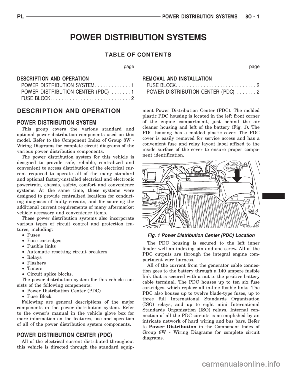
this vehicle is directed through the standard equip-ment Power Distribution Center (PDC). The molded
plastic PDC housing is located in the left front corner
of the engine compartment, just behind the air
cleaner housing and left of the battery (Fig. 1). The
PDC housing has a molded plastic cover. The PDC
cover is easily removed for service access and has a
convenient fuse and relay layout label affixed to the
inside surface of the cover to ensure proper compo-
nent identification.
The PDC housing is secured to the left inner
fender well an indexing pin and one screw. All of the
PDC outputs are through the integral engine com-
partment wire harness.
All of the current from the generator cable connec-
tion goes to the battery through a 140 ampere fusible
link that is secured with a nut to the positive battery
cable terminal. The PDC houses up to ten six fuse
cartridges, which replace all in-line fusible links. The
PDC also houses up to twelve blade-type fuses, up to
three full International Standards Organization
(ISO) relays, and up to eight mini International
Standards Organization (ISO) relays. Internal con-
nection of all the PDC circuits is accomplished by an
intricate network of hard wiring and bus bars. Refer
toPower Distributionin the Component Index of
Group 8W - Wiring Diagrams for complete circuit
diagrams.
Fig. 1 Power Distribution Center (PDC) Location
PLPOWER DISTRIBUTION SYSTEMS 8O - 1
Page 410 of 1285
8W-02 COMPONENT INDEX
Component Page
A/C Compressor Clutch Relay............8W-42
A/C Compressor Clutch.................8W-42
A/C Cycling Switch....................8W-42
A/C Heater Blower Motor...............8W-42
A/C Heater Control....................8W-42
A/C Pressure Switches..................8W-42
Airbag Control Module.................8W-43
Airbags.............................8W-43
Antenna.............................8W-47
Automatic Shut Down Relay.............8W-30
Back-Up Lamp Switch..................8W-51
Back-Up Lamps.......................8W-51
Battery.............................8W-20
Blower Motor Resistor Block.............8W-42
Brake Lamp Switch....................8W-30
Brake Shift Interlock Solenoid...........8W-30
Brake Warning Indicator Switch..........8W-40
Camshaft Position Sensor...............8W-30
Cargo Lamp..........................8W-44
Center High Mounted Stop Lamp.........8W-51
Center Stack Lamp....................8W-44
Cigar Lighter/Power Outlet..............8W-41
Circuit Breakers (FB)..................8W-11
City Lamps..........................8W-50
Clockspring.....................8W-33, 41, 43
Clutch Interlock Switch.................8W-30
Combination Flasher...................8W-52
Controller Anti-Lock Brake..............8W-35
Crankshaft Position Sensor..............8W-30
Data Link Connector...................8W-30
Decklid Release Switch.................8W-44
Decklid Solenoid......................8W-61
Diode No. 1..........................8W-42
Dome Lamp..........................8W-44
Dome Lamp/Intrusion Sensor............8W-44
Door Ajar Switches....................8W-40
Door Lock Motors.....................8W-61
Engine Coolant Temperature Sensor.......8W-30
Engine Oil Pressure Switch..............8W-30
Engine Starter Motor Relay.............8W-21
Engine Starter Motor..................8W-21
Fog Lamps........................8W-50, 51
Front Fog Lamp Switch.................8W-50
Fuel Injectors........................8W-30
Fuel Pump Module....................8W-30
Fuel Pump Relay......................8W-30
Fuel Tank...........................8W-30
Fuses (FB)...........................8W-11
Fuses (PDC).........................8W-10
Fuse Block...........................8W-11
Fusible Link A11...................8W-20, 21
Grounds.............................8W-15Component Page
Generator...........................8W-20
Glove Box Lamp/Switch.................8W-44
Headlamp Beam Select..............8W-40, 50
Headlamp Leveling Motors..............8W-50
Headlamp Leveling Switch Illumination....8W-50
Headlamp Leveling Switch..............8W-50
Headlamp Switch...................8W-50, 51
Headlamps..........................8W-50
Horns..............................8W-41
Horn Relay..........................8W-41
Horn Switch.........................8W-41
Hood Ajar Switch......................8W-39
Idle Air Control Motor..................8W-30
Ignition Coil.........................8W-30
Ignition Switch.......................8W-10
Indicators...........................8W-40
Indicator Drivers......................8W-40
Inlet Air Temperature Sensor............8W-30
Instrument Cluster....................8W-40
Instrument Panel Drivers...............8W-40
Knock Sensor.........................8W-30
Leak Detection Pump..................8W-30
License Lamps........................8W-51
Manifold Absolute Pressure Sensor........8W-30
Map/Reading Lamps...................8W-44
Multi- Function Switch.........8W-40, 50, 51, 52
Noise Suppressor......................8W-30
Oxygen Sensors.......................8W-30
Park Brake Switch....................8W-40
Park/Neutral Position Switch............8W-51
Park/Turn Signal Lamps................8W-52
Power Distribution Center...............8W-10
Power Mirror Switch...................8W-62
Power Steering Pressure Switch..........8W-30
Powertrain Control Module..............8W-30
PRNDL Lamp........................8W-44
Proportional Evap/Purge Solenoid.........8W-30
Radiator Fan Motor....................8W-42
Radiator Fan Relay....................8W-42
Radio...............................8W-47
Rear Window Defogger Switch...........8W-48
Rear Window Defogger.................8W-48
Remote Keyless Entry Module............8W-39
Repeater Lamps......................8W-52
Seat Belt Switch......................8W-40
Sentry Key Immobilizer Module..........8W-39
Side Marker Lamps....................8W-50
Siren...............................8W-39
Speakers............................8W-47
Splice Information.....................8W-70
Sunroof Control Module................8W-64
Sunroof Motor........................8W-64
PL8W - 02 COMPONENT INDEX 8W - 02 - 1
Page 412 of 1285
8W-10 POWER DISTRIBUTION
Component Page
A/C Compressor Clutch Relay........8W-10-7, 16
Automatic Shut Down Relay...........8W-10-16
Battery............................8W-10-7
Brake Lamp Switch................8W-10-7, 18
Cargo Lamp.......................8W-10-12
Center High Mounted Stop Lamp.......8W-10-18
Cigar Lighter/Power Outlet............8W-10-8
Circuit Breaker No. 1 (FB).............8W-10-9
Circuit Breaker No. 2 (FB).............8W-10-9
Combination Flasher.................8W-10-13
Controller Anti-Lock Brake.......8W-10-7, 11, 18
Data Link Connector.................8W-10-16
Dome Lamp.......................8W-10-12
Dome Lamp/Intrusion Sensor..........8W-10-12
Engine Starter Motor.................8W-10-8
Engine Starter Motor Relay........8W-10-7, 8, 10
Front Fog Lamp Switch..............8W-10-14
Fuel Injector No. 1..................8W-10-17
Fuel Injector No. 2..................8W-10-17
Fuel Injector No. 3..................8W-10-17
Fuel Injector No. 4..................8W-10-17
Fuel Pump Module..................8W-10-16
Fuel Pump Relay...................8W-10-16
Fuse 1 (FB)........................8W-10-10
Fuse 2 (FB)........................8W-10-10
Fuse 5 (PDC).......................8W-10-7
Fuse 6 (FB).........................8W-10-9
Fuse 6 (PDC).....................8W-10-7, 11
Fuse 7 (FB).........................8W-10-9
Fuse 8 (FB).........................8W-10-9
Fuse 8 (PDC).....................8W-10-7, 11
Fuse 9 (FB)........................8W-10-10
Fuse 9 (PDC)......................8W-10-7, 8
Fuse 10 (FB).......................8W-10-10
Fuse 10 (PDC)....................8W-10-7, 11
Fuse 11 (FB).......................8W-10-10
Fuse 12 (FB).......................8W-10-10
Fuse 13 (PDC)....................8W-10-7, 12
Fuse 14 (FB)........................8W-10-9
Fuse 14 (PDC).....................8W-10-7, 8
Fuse 15 (FB)........................8W-10-9
Fuse 15 (PDC)....................8W-10-7, 13
Fuse 16 (FB)........................8W-10-9Component Page
Fuse 18 (PDC)....................8W-10-7, 13
Fuse 20 (FB).......................8W-10-11
Fuse 20 (PDC)....................8W-10-7, 14
Fuse 21 (PDC)....................8W-10-7, 16
Fuse 22 (PDC)....................8W-10-7, 16
Fuse 23 (PDC)....................8W-10-7, 18
Fuse Block....................8W-10-9, 10, 11
Generator.........................8W-10-17
Glove Box Lamp/Switch..............8W-10-12
Headlamp Switch...................8W-10-14
High Note Horn....................8W-10-13
Horn Relay......................8W-10-7, 13
Ignition Coil.......................8W-10-17
Ignition Switch................8W-10-7, 8, 9, 10
Instrument Cluster.............8W-10-8, 12, 14
Instrument Panel Drivers.............8W-10-14
Left Front Fog Lamp..............8W-10-14, 15
Left Tail/Stop Lamp.................8W-10-18
Left Tail/Stop/Turn Signal Lamp........8W-10-19
Left Visor/Vanity Lamp...............8W-10-12
Low Note Horn.....................8W-10-13
Map/Reading Lamps.................8W-10-12
Multi-Function Switch......8W-10-7, 13, 14, 15, 19
Noise Suppressor...................8W-10-17
Oxygen Sensor 1/1 Upstream..........8W-10-17
Oxygen Sensor 1/2 Downstream........8W-10-17
Power Distribution Center.....8W-10-2, 3, 4, 7, 8,
9, 11, 12, 13, 14, 16, 18
Powertrain Control Module.........8W-10-16, 17
Radiator Fan Motor.................8W-10-11
Radiator Fan Relay................8W-10-7, 11
Radio.............................8W-10-12
Rear Window Defogger...............8W-10-11
Rear Window Defogger Switch.........8W-10-11
Remote Keyless Entry Module.........8W-10-12
Right Front Fog Lamp...............8W-10-15
Right Rear Fog Lamp................8W-10-14
Right Tail/Stop Lamp................8W-10-18
Right Tail/Stop/Turn Signal Lamp......8W-10-19
Right Visor/Vanity Lamp..............8W-10-12
Sentry Key Immobilizer Module........8W-10-12
Siren.............................8W-10-12
Underhood Lamp...................8W-10-12
PL8W - 10 POWER DISTRIBUTION 8W - 10 - 1
Page 423 of 1285

13FUSE15A
13
BATT A0
B5C103
M1
20
WT
LAMP UNDERHOOD
M1
20
PK
LAMP CARGO
LAMP
DOMEM1
20
PK
1C204
M1
18
BK/PK
M1
20
PK
1
7
RADIO
M1
20
PK
21
CLUSTER INSTRUMENT
M1
20
PK
M1
18
BK/PK
C
MAP/
READING
LAMPS
M1
18
BK/PK
LAMP VANITY
VISOR/
LEFT RIGHT
VISOR/
VANITY
LAMP
BK/PK18 M1
S251
2
CENTER DISTRIBUTION
POWER
C2
SWITCH LAMP/
BOX
GLOVE
1
6
C1071
PK20 M1
1
S103
M1
20
PK
M1
20
PK
5M1
20
PK
10C105
S309
M1
20
PK
M1
20
PK
M1
20
PK
MODULE IMMOBILIZER
KEY
SENTRY
4
M1
20
PK
(BUILT-UP- SIREN
EXPORT)
C3011
21
M1
20
PK
BUILT-UP- (LHD
MODULE
ENTRY
KEYLESS
REMOTE
EXPORT)S201
EXCEPT
EXPORTUP- BUILT-
EXPORTUP- BUILT-
PK20 M1
2
DOME
LAMP/
INTRUSION
SENSOR
S133
M1
20
PK
(8W-44-4)(8W-44-4)
(8W-44-2)
(8W-47-2)
(8W-40-2)
(8W-44-3)
(8W-44-4) (8W-44-4) (8W-10-7)
(8W-44-4)(8W-10-2)
(8W-10-3)
(8W-39-3) (8W-39-14)
(8W-39-2)(8W-44-2)
8W - 10 - 12 8W-10 POWER DISTRIBUTIONPL
008W-10PLI01012
Page 536 of 1285
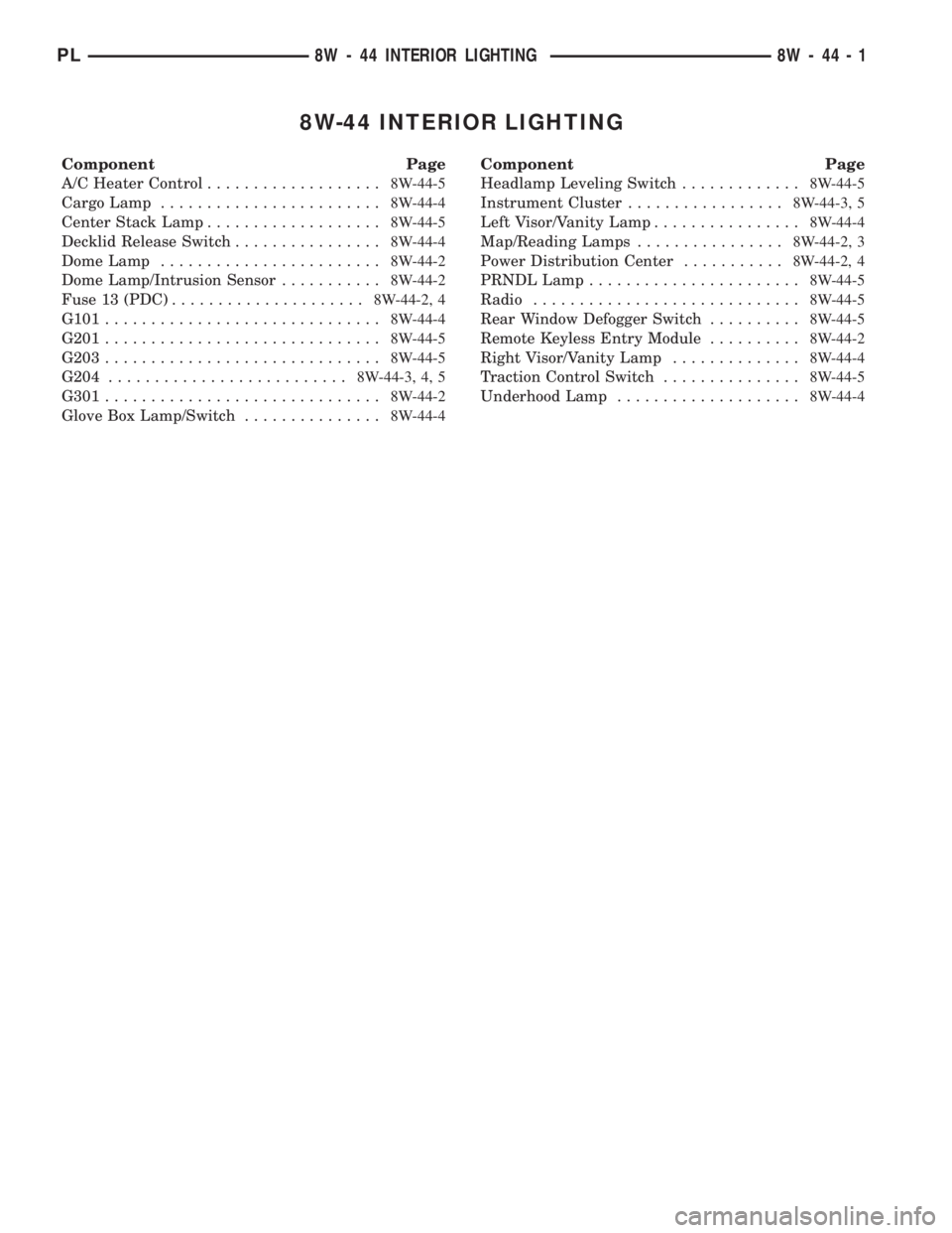
8W-44 INTERIOR LIGHTING
Component Page
A/C Heater Control...................8W-44-5
Cargo Lamp........................8W-44-4
Center Stack Lamp...................8W-44-5
Decklid Release Switch................8W-44-4
Dome Lamp........................8W-44-2
Dome Lamp/Intrusion Sensor...........8W-44-2
Fuse 13 (PDC).....................8W-44-2, 4
G101..............................8W-44-4
G201..............................8W-44-5
G203..............................8W-44-5
G204..........................8W-44-3, 4, 5
G301..............................8W-44-2
Glove Box Lamp/Switch...............8W-44-4Component Page
Headlamp Leveling Switch.............8W-44-5
Instrument Cluster.................8W-44-3, 5
Left Visor/Vanity Lamp................8W-44-4
Map/Reading Lamps................8W-44-2, 3
Power Distribution Center...........8W-44-2, 4
PRNDL Lamp.......................8W-44-5
Radio.............................8W-44-5
Rear Window Defogger Switch..........8W-44-5
Remote Keyless Entry Module..........8W-44-2
Right Visor/Vanity Lamp..............8W-44-4
Traction Control Switch...............8W-44-5
Underhood Lamp....................8W-44-4
PL8W - 44 INTERIOR LIGHTING 8W - 44 - 1
Page 539 of 1285

13
15A
FUSE
13
BATT A0
POWER
DISTRIBUTION
CENTER
1
2
G101
S112
C1071
UNDERHOOD
LAMP
21
SWITCH LAMP/
BOX
GLOVE
G204
S205
LAMP
VANITY
VISOR/
LEFT RIGHT
VISOR/
VANITY
LAMP
C204121
DECKLID
RELEASE CARGO
LAMP
C3023
S309
10C105
B5C1035
S201
M1
20
PK
M1
20
PK
M1
20
WT
M1
18
BK/PK
M1
18
BK/PKM1
18
BK/PK
M1
20
PKM1
20
PK
M1
20
PK
M1
20
PKM1
20
PK
M1
20
PK
Z1
20
BK
Z1
18
BK
Z3
20
BK/OR
Z3
14
BK/OR
S103
S251
G78
22
TN/BK
G78
18
TN/BK
SWITCH
2C107
BK20Z1
S133
S134
Z1
20
BK
M1
20
PK
(8W-10-12)(8W-10-7)
(8W-10-2)
(8W-10-3)
(8W-15-3) (8W-15-3)
(8W-15-11) (8W-15-11)(8W-10-12)
(8W-10-12)(8W-10-12)
(8W-10-12) (8W-10-12)
(8W-15-3)
8W - 44 - 4 8W-44 INTERIOR LIGHTINGPL
008W-10PLI04404
Page 634 of 1285

CAV CIRCUIT FUNCTION
1 Z1 18BK GROUND
2 Z2 18BK/LG GROUND
3 G4 18DB FUEL LEVEL SENSOR SIGNAL
4 A141 18DG/WT FUEL PUMP RELAY OUTPUT
LT GRAY
4
1
BLACK
CAV CIRCUIT FUNCTION
1
A142 18DG/OR AUTOMATIC SHUT DOWN RELAY OUTPUT 2K20 18DG GENERATOR FIELD DRIVER (+) 2
1
CAV CIRCUIT FUNCTION
1M1 20PK FUSED B (+)
2Z3 20BK/OR GROUND
1 2
FUEL PUMP
MODULE
GENERATOR
LAMP/SWITCHGLOVE BOX
HIGH
18BK Z1
2
18DG/RD X2 1
1
2BLACK
CAV CIRCUIT FUNCTION
GROUND
HORN RELAY OUTPUT
(BUILT-UP-EXPORT)SWITCH HEADLAMP LEVELING
L13 20BR/YL
E2 22OR
5 4
Z1 20BK 3
1
- - 2 L43 18VT CAV CIRCUIT FUNCTION
GROUND HEADLAMP ADJUST SIGNAL
FUSED LEFT LOW BEAM OUTPUT
PANEL LAMPS DRIVER 4
1
BLACK
BLACK
NOTE
HORN
PL8W-80 CONNECTOR PIN-OUTS 8W - 80 - 25
PLI08025J008W-10
Page 1242 of 1285
BLOWER MOTOR VIBRATION AND/OR NOISE
DIAGNOSIS
The resistor block supplies the blower motor with
varied voltage (low and middle speeds) or battery
voltage (high speed).
CAUTION: Stay clear of the blower motor and resis-
tor block (Hot). Do not operate the blower motor
with the resistor block removed from the heater-A/C
housing.
Refer to the Blower Motor Vibration/Noise chart
for diagnosis.
COMPRESSOR NOISE DIAGNOSIS
Excessive noise while the A/C is being used, can be
caused by loose mounts, loose clutch, or high operat-
ing pressure. Verify compressor drive belt condition,
proper refrigerant charge and head pressure before
compressor repair is performed.
If the A/C drive belt slips at initial start-up, it does
not necessarily mean the compressor has failed.
With the close tolerances of a compressor it is pos-
sible to experience a temporary lockup. The longer
the A/C system is inactive, the more likely the condi-
tion to occur.
This condition is the result of normal refrigerant
movement within the A/C system caused by temper-
ature changes. The refrigerant movement may wash
the oil out of the compressor.
EVAPORATOR PROBE TEST
The work area and vehicle must be between 16É C
(60É F) and 32É C (90É F) when testing the switch.
(1) Disconnect the three wire connector from the
evaporator probe lead located behind the glove box
(Fig. 12).
(2) Start engine and set A/C to low blower motor
speed, panel, full cool, and RECIRC.
(3) Using a voltmeter, check for battery voltage
between Pin 1 and 2. If no voltage is detected, there
is no power to the switch. Check wiring and fuses.
Refer to Group 8W, Wiring Diagrams for circuit diag-
nosis.
(4) Using a voltmeter, check for battery voltage
between Pin 1 and Pin 3. If no voltage is detected,
there is no voltage from the Powertrain Control Mod-
ule. Refer to Group 8W, Wiring Diagrams. If voltage
is OK, connect a jumper wire between Pin 1 and Pin
3. The compressor clutch should engage. If the clutch
engages, remove the jumper wire immediately and go
to Step 5. If the compressor clutch does not engage,
check the operation of the clutch and repair as nec-
essary.(5) If compressor clutch engages, connect the evap-
orator probe 3-way connector. The compressor clutch
should engage or cycle depending on evaporator tem-
perature. If OK, go to Step 6. If not OK, replace the
clutch cycling switch.
(6) The engine running and the A/C set to:
²Blower motor on low speed
²Panel position
²Full cool
²RECIRC.
Close all doors and windows. Place a thermometer in
the center discharge vent.
(7) If the clutch does not begin to cycle off between
2É C to 7É C (35É F to 45É F), verify that the evapo-
rator probe is fully installed and not loose in evapo-
rator. If it is not properly installed, install probe and
retest outlet temperature. If the evaporator probe is
properly installed, replace the clutch cycling switch.
EXPANSION VALVE
NOTE: Expansion valve tests should be performed
after compressor tests.
Liquid CO2 is required to test the expansion
valve. It is available from most welding supply facil-
ities. CO2 is also available from companies which
service and sell fire extinguishers.
Review Safety Precautions and Warnings in the
General Information section of this Group. The work
area and vehicle must be 21É to 27ÉC (70É to 85ÉF)
when testing expansion valve. To test the expansion
valve:
(1) Connect a charging station or manifold gauge
set to the refrigerant system service ports.
(2) Disconnect wire connector at low pressure cut-
off switch (Fig. 13). Using a jumper wire, jump ter-
minals inside wire connector boot.
(3) Close all doors, windows and vents to the pas-
senger compartment.
(4) Set Heater-A/C control to A/C, full heat, floor,
RECIRC. and high blower.
(5) Start the engine and hold the idle speed (1000
rpm). After the engine has reached running temper-
ature, allow the passenger compartment to heat up.
This will create the need for maximum refrigerant
flow into the evaporator.
(6) If the refrigerant charge is sufficient, discharge
(high pressure) gauge should read 965 to 2620 kPa
(140 to 380 psi). Suction (low pressure) gauge should
read 103 to 2417 kPa (15 to 35 psi). If system cannot
achieve proper pressure readings, replace the expan-
sion valve. If pressure is correct, proceed with test.
PLHEATING AND AIR CONDITIONING 24 - 11
DIAGNOSIS AND TESTING (Continued)