obd DODGE NEON 2000 Service Repair Manual
[x] Cancel search | Manufacturer: DODGE, Model Year: 2000, Model line: NEON, Model: DODGE NEON 2000Pages: 1285, PDF Size: 29.42 MB
Page 232 of 1285
CHARGING SYSTEM
TABLE OF CONTENTS
page page
DESCRIPTION AND OPERATION
CHARGING SYSTEM.......................1
GENERATOR.............................1
ELECTRONIC VOLTAGE REGULATOR..........1
REMOVAL AND INSTALLATION
GENERATOR.............................2SPECIFICATIONS
GENERATOR RATINGS.....................3
TORQUE................................3
DESCRIPTION AND OPERATION
CHARGING SYSTEM
DESCRIPTION
The charging system consists of:
²Generator
²Electronic Voltage Regulator (EVR) circuitry
within the Powertrain Control Module (PCM)
²Ignition switch (refer to the Ignition System for
information)
²Battery (refer to the Battery for information)
²Battery temperature sensor
²Wiring harness and connections (refer to the
Wiring for information)
OPERATION
The charging system is turned on and off with the
ignition switch. When the ignition switch is turned to
the ON position, battery voltage is applied to the
generator rotor through one of the two field termi-
nals to produce a magnetic field. The generator is
driven by the engine through a serpentine belt and
pulley arrangement.
The amount of DC current produced by the gener-
ator is controlled by the EVR (field control) circuitry,
contained within the PCM. This circuitry is con-
nected in series with the second rotor field terminal
and ground.
Temperature data, along with data from monitored
line voltage, is used by the PCM to vary the battery
charging rate. This is done by cycling the ground
path to control the strength of the rotor magnetic
field. The PCM then compensates and regulates gen-
erator current output accordingly and to maintain
the proper voltage depending on battery tempera-
ture.
All vehicles are equipped with On-Board Diagnos-
tics (OBD). All OBD-sensed systems, including the
EVR (field control) circuitry, are monitored by thePCM. Each monitored circuit is assigned a Diagnos-
tic Trouble Code (DTC). The PCM will store a DTC in
electronic memory for any failure it detects.
GENERATOR
DESCRIPTION
The generator is belt-driven by the engine. It is
serviced only as a complete assembly. If the genera-
tor fails for any reason, the entire assembly must be
replaced.
OPERATION
As the energized rotor begins to rotate within the
generator, the spinning magnetic field induces a cur-
rent into the windings of the stator coil. Once the
generator begins producing sufficient current, it also
provides the current needed to energize the rotor.
The Y type stator winding connections deliver the
induced AC current to 3 positive and 3 negative
diodes for rectification. From the diodes, rectified DC
current is delivered to the vehicles electrical system
through the generator, battery, and ground terminals.
Noise emitting from the generator may be caused
by:
²Worn, loose or defective bearings
²Loose or defective drive pulley
²Incorrect, worn, damaged or misadjusted drive
belt
²Loose mounting bolts
²Misaligned drive pulley
²Defective stator or diode
²Damaged internal fins
ELECTRONIC VOLTAGE REGULATOR
DESCRIPTION
The Electronic Voltage Regulator (EVR) is not a
separate component. It is actually a voltage regulat-
ing circuit located within the Powertrain Control
PLCHARGING SYSTEM 8C - 1
Page 825 of 1285
The inlet strainer, fuel pressure regulator and fuel
level sensor are the only serviceable items. If the fuel
pump requires service, replace the fuel pump module.
ELECTRIC FUEL PUMP
DESCRIPTION
The electric fuel pump is located in and is part of
the fuel pump module. It is a positive displacement,
gerotor type, immersible pump with a permanent
magnet electric motor. The fuel pump module is sus-
pended in fuel in the fuel tank.
OPERATION
The pump draws fuel through a strainer and
pushes it through the motor to the outlet. The pump
contains a check valve. The valve, in the pump out-
let, maintains pump pressure during engine off con-
ditions. The fuel pump relay provides voltage to the
fuel pump. The fuel pump has a maximum dead-
headed pressure output of approximately 880 kPa
(130 psi). The regulator adjusts fuel system pressure
to approximately 338 kPa (49 psi).
FUEL GAUGE SENDING UNIT
DESCRIPTION
The fuel gauge sending unit (fuel level sensor) is
attached to the side of the fuel pump module. The
sending unit consists of a float, an arm, and a vari-
able resistor (track). The resistor track is used to
send electrical signals to the instrument cluster for
fuel gauge operation and are then transmitted to the
engine controller for OBDII emission requirements.
OPERATION
For fuel gauge operation:As fuel level
increases, the float and arm move up. This increases
the sending unit resistance, causing the fuel gauge to
read full. As fuel level decreases, the float and arm
move down. This decreases the sending unit resis-
tance causing the fuel gauge to read empty.
After this fuel level signal is sent to the instru-
ment cluster, the instrument cluster will transmit
the data across the J1850 bus circuit to the PCM.
For OBD II emission requirements:The voltage
signal is sent to the instrument cluster to indicate
fuel level. The cluster transmits the fuel level to the
PCM where it is used to prevent a false setting of
misfire and fuel system monitor trouble codes. This
occurs if the fuel level in the tank is less than
approximately 15 percent of its rated capacity.
FUEL FILTER/FUEL PRESSURE REGULATOR
DESCRIPTION
A combination fuel filter and fuel pressure regula-
tor is used on all gas powered engines. It is located
on the top of the fuel pump module. A separate frame
mounted fuel filter is not used.
OPERATION
Fuel Pressure Regulator Operation:The pres-
sure regulator is a mechanical device that is cali-
brated to maintain fuel system operating pressure of
approximately 338 kPa (49 psi) at the fuel injectors.
It contains a diaphragm, calibrated springs and a
fuel return valve. The internal fuel filter (Fig. 2) is
also part of the assembly.
Fuel is supplied to the filter/regulator by the elec-
tric fuel pump through an opening tube at the bot-
tom of filter/regulator.
The fuel pump module contains a check valve to
maintain some fuel pressure when the engine is not
operating. This will help to start the engine.
If fuel pressure at the pressure regulator exceeds
approximately 49 psi, an internal diaphragm closes
and excess fuel pressure is routed back into the tank
through the pressure regulator. A separate fuel
return line is not used with any gas powered engine.
FUEL TANK
OPERATION
All models pass a full 360 degree rollover test
without fuel leakage. To accomplish this, fuel and
vapor flow controls are required for all fuel tank con-
nections.
All models are equipped with either one or two
rollover valves mounted into the top of the fuel tank
(or pump module).
An evaporation control system is connected to the
rollover valve(s) to reduce emissions of fuel vapors
into the atmosphere. When fuel evaporates from the
fuel tank, vapors pass through vent hoses or tubes to
a charcoal canister where they are temporarily held.
When the engine is running, the vapors are drawn
into the intake manifold. Certain models are also
equipped with a self-diagnosing system using a Leak
Detection Pump (LDP). Refer to the Emission Control
System for additional information.
FUEL RAIL
DESCRIPTION
The fuel rail supplies the necessary fuel to each
individual fuel injector and is mounted to the intake
manifold (Fig. 3).
14 - 4 FUEL SYSTEMPL
DESCRIPTION AND OPERATION (Continued)
Page 849 of 1285
BATTERY VOLTAGEÐPCM INPUT
OPERATION
In order for the PCM to operate, it must be sup-
plied with battery voltage and ground. The PCM
monitors the direct battery feed input to determine
battery charging rate and to control the injector ini-
tial opening point. It also has back-up RAM memory
used to store Diagnostic Trouble Codes (supply work-
ing DTCs). Direct battery feed is also used to perform
key-OFF diagnostics and to supply working voltage
to the controller for OBDII.
The five and eight volt regulators are protected
from shorts to ground. This protection allows diag-
nostics to be performed should the five volt power
supply become shorted to ground at any of the sen-
sors. A short to ground in the five volt power supply
will cause a ªno-startº situation. There is a Diagnos-
tic Trouble Code (DTC) if the five-volt power supply
becomes shorted to ground. Refer to the Diagnostic
Procedures Manual for more details on any on-board
diagnostic information.
If battery voltage is low the PCM will increase
injector pulse width (period of time that the injector
is energized).
The direct battery feed to the PCM is used as a
reference point to sense battery voltage.
Effect on Fuel Injectors
Fuel injectors are rated for operation at a specific
voltage. If the voltage increases, the plunger will
open faster and further (more efficient) and con-
versely, if voltage is low the injector will be slow to
open and will not open as far. Therefore, if sensed
battery voltage drops, the PCM increases injector
pulse-width to maintain the same volume of fuel
through the injector.
Charging
The PCM uses sensed battery voltage to verify that
target charging voltage (determined by Battery Tem-
perature Sensor) is being reached. To maintain the
target charging voltage, the PCM will full field the
generator to 0.5 volt above target then turn OFF to
0.5 volt below target. This will continue to occur up
to a 100 Hz frequency, 100 times per second.
BRAKE SWITCHÐPCM INPUT
OPERATION
When the brake switch is activated, the PCM
receives an input indicating that the brakes are
being applied. The brake switch is mounted on the
brake pedal support bracket.
CAMSHAFT POSITION SENSORÐPCM INPUT
DESCRIPTION
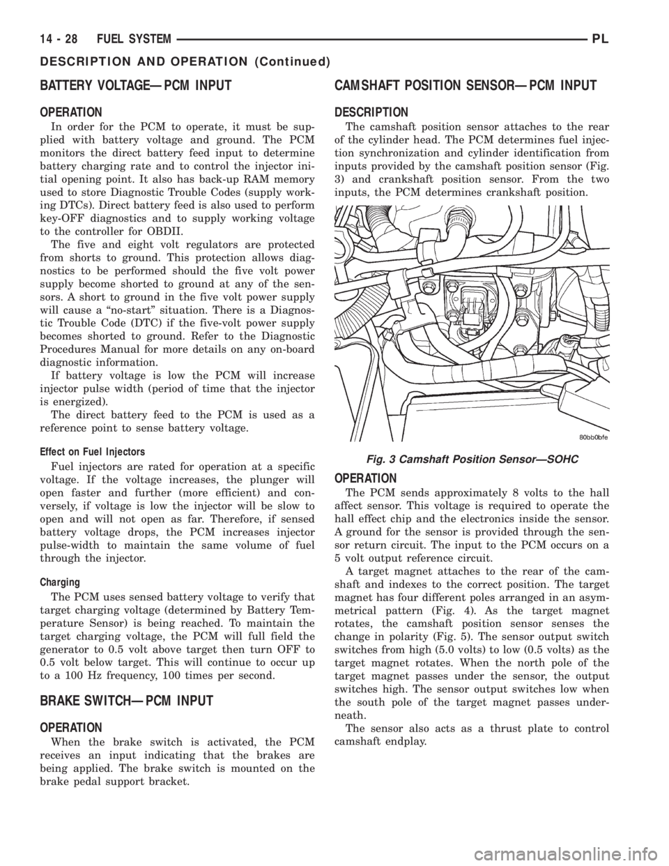
The camshaft position sensor attaches to the rear
of the cylinder head. The PCM determines fuel injec-
tion synchronization and cylinder identification from
inputs provided by the camshaft position sensor (Fig.
3) and crankshaft position sensor. From the two
inputs, the PCM determines crankshaft position.
OPERATION
The PCM sends approximately 8 volts to the hall
affect sensor. This voltage is required to operate the
hall effect chip and the electronics inside the sensor.
A ground for the sensor is provided through the sen-
sor return circuit. The input to the PCM occurs on a
5 volt output reference circuit.
A target magnet attaches to the rear of the cam-
shaft and indexes to the correct position. The target
magnet has four different poles arranged in an asym-
metrical pattern (Fig. 4). As the target magnet
rotates, the camshaft position sensor senses the
change in polarity (Fig. 5). The sensor output switch
switches from high (5.0 volts) to low (0.5 volts) as the
target magnet rotates. When the north pole of the
target magnet passes under the sensor, the output
switches high. The sensor output switches low when
the south pole of the target magnet passes under-
neath.
The sensor also acts as a thrust plate to control
camshaft endplay.
Fig. 3 Camshaft Position SensorÐSOHC
14 - 28 FUEL SYSTEMPL
DESCRIPTION AND OPERATION (Continued)
Page 854 of 1285
grammed (fixed) values and inputs from other sen-
sors.
DOWNSTREAM OXYGEN SENSOR 1/2
The Downstream O2 Sensor has two functions.
One function is measuring catalyst efficiency. This is
an OBD II requirement. The oxygen content of theexhaust gasses has significantly less fluctuation than
at the inlet if the converter is working properly. The
PCM compares upstream and Downstream O2 Sen-
sor switch rates under specific operating conditions
to determine if the catalyst is functioning properly.
The other function is a downstream fuel control
which was introduced in 1996. The upstream O2 goal
varies within the window of operation of the O2 Sen-
sor. In the past the goal was a preprogrammed fixed
value based upon where it believed the catalyst oper-
ated most efficiently.
While the Upstream O2 Sensor input is used to
maintain the 14.7:1 air/fuel ratio, variations in
engines, exhaust systems and catalytic converters
may cause this ratio to not be the most ideal for a
particular catalyst and engine. To help maintain the
catalyst operating at maximum efficiency, the PCM
will fine tune the air/fuel ratio entering the catalyst
based upon the oxygen content leaving the catalyst.
This is accomplished by modifying the Upstream O2
Sensor voltage goal.
If the exhaust leaving the catalyst has too much
oxygen (lean ) the PCM increases the upstream O2
goal which increases fuel in the mixture causing less
oxygen to be left over. Conversely, if the oxygen con-
tent leaving the catalyst has is too little oxygen (rich)
the PCM decreases the upstream O2 goal down
which removes fuel from the mixture causing more
oxygen to be left over. This function only occurs dur-
ing downstream closed loop mode operation.
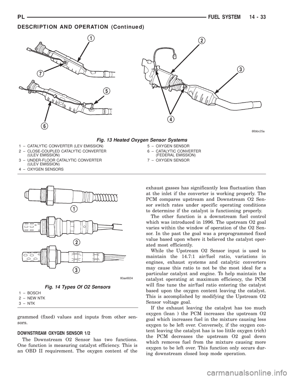
Fig. 13 Heated Oxygen Sensor Systems
1 ± CATALYTIC CONVERTER (LEV EMISSION)
2 ± CLOSE-COUPLED CATALYTIC CONVERTER
(ULEV EMISSION)
3 ± UNDER-FLOOR CATALYTIC CONVERTER
(ULEV EMISSION)
4 ± OXYGEN SENSORS5 ± OXYGEN SENSOR
6 ± CATALYTIC CONVERTER
(FEDERAL EMISSION)
7 ± OXYGEN SENSOR
Fig. 14 Types Of O2 Sensors
1 ± BOSCH
2 ± NEW NTK
3 ± NTK
PLFUEL SYSTEM 14 - 33
DESCRIPTION AND OPERATION (Continued)
Page 855 of 1285
IGNITION CIRCUIT SENSEÐPCM INPUT
OPERATION
The ignition circuit sense input tells the Power-
train Control Module (PCM) the ignition switch has
energized the ignition circuit.
Battery voltage is also supplied to the PCM
through the Ignition Switch when the ignition is in
the RUN or START position. This is called the9igni-
tion senseº circuit and is used to ªwake upº the PCM.
Voltage on the ignition input can be as low as 6 volts
and the PCM will still function. Voltage is supplied to
this circuit to power the 8-volt regulator and to allow
the PCM to perform fuel, ignition and emissions con-
trol functions. The battery voltage on this line is sup-
plied to the 8-volt regulator which then passes on a
power-up supply to the 5-volt regulator.
INLET AIR TEMPERATURE SENSORÐPCM
INPUT
DESCRIPTION
The IAT sensor attaches to the intake air duct
(Fig. 15).
The IAT Sensor is a Negative Temperature Coeffi-
cient (NTC) Sensor that provides information to the
PCM regarding the temperature of the air entering
the intake manifold.
OPERATION
Intake Air Temperature
The inlet air temperature sensor replaces the
intake air temperature sensor and the battery tem-
perature sensor. The PCM uses the information from
the inlet air temperature sensor to determine valuesto use as an intake air temperature sensor and a bat-
tery temperature sensor.
The Intake Air Temperature (IAT) sensor value is
used by the PCM to determine air density.
The PCM uses this information to calculate:
²Injector pulse width
²Adjustment of ignition timing (to prevent spark
knock at high intake air temperatures)
Battery Temperature
The inlet air temperature sensor replaces the
intake air temperature sensor and the battery tem-
perature sensor. The PCM uses the information from
the inlet air temperature sensor to determine values
for the PCM to use as an intake air temperature sen-
sor and a battery temperature sensor.
The battery temperature information along with
data from monitored line voltage (B+), is used by the
PCM to vary the battery charging rate. System volt-
age will be higher at colder temperatures and is
gradually reduced at warmer temperatures.
The battery temperature information is also used
for OBD II diagnostics. Certain faults and OBD II
monitors are either enabled or disabled depending
upon the battery temperature sensor input (example:
disable purge and EGR, enable LDP). Most OBD II
monitors are disabled below 20ÉF.
KNOCK SENSORÐPCM INPUT
DESCRIPTION
The knock sensor threads into the side of the cyl-
inder block (Fig. 16). The knock sensor is designed to
detect engine vibration that is caused by detonation.
Fig. 15 Inlet Air Temperature Sensor
Fig. 16 Knock Sensor
14 - 34 FUEL SYSTEMPL
DESCRIPTION AND OPERATION (Continued)
Page 858 of 1285
position of the throttle blade changes, the resistance
of the TPS changes.
OPERATION
The PCM supplies approximately 5 volts DC to the
TPS. The TPS output voltage (input signal to the
powertrain control module) represents throttle blade
position. The TPS output voltage to the PCM varies
from approximately 0.35 to 1.03 volts at minimum
throttle opening (idle) to a maximum of 3.1 to 4.0
volts at wide open throttle.
Along with inputs from other sensors, the PCM
uses the TPS input to determine current engine oper-
ating conditions. The PCM also adjusts fuel injector
pulse width and ignition timing based on these
inputs.
When the TPS indicates a voltage that is too high,
too low or not believable, the PCM sets a DTC. When
the DTC is set, the MIL is illuminated and the PCM
moves into limp-in mode. Limp-in for the TPS is
divided into three categories:
²Idle
²Part-throttle
²Wide open throttle (WOT)
VEHICLE SPEED SIGNAL (VSS)ÐPCM INPUT
DESCRIPTION
The PCM requires the VSS to be able to control
the following programs:
²Speed Control
²IAC motor (during deceleration)
²Injection pulse width (during deceleration)
²OBD II diagnostics
²PCM mileage EEPROM
²Road speed shutdown
²Speedometer/Odometer (bused message)NOTE: Road Speed Shutdown is the PCM shutting
off fuel injectors above a preset vehicle speed.
The vehicle speed sensor is located in the transmis-
sion extension housing (Fig. 21) and (Fig. 22).
OPERATION
The vehicle speed sensor on 3 speed automatic and
manual transaxle vehicles is a Hall-effect sensor.
This sensor is mechanically driven by a pinion gear
that is in mesh with the right axle drive shaft. The
hall-effect sensor switches a 5 volt signal sent from
the PCM from a ground to an open circuit.
Fig. 20 Throttle Position Sensor and Idle Air Control
Motor
Fig. 21 Vehicle Speed SensorÐAutomatic
Transmission
1 ± TRANSAXLE EXTENSION HOUSING
2 ± VEHICLE SPEED SENSOR
Fig. 22 Vehicle Speed SensorÐManual
Transmission
1 ± TRANSAXLE
2 ± SPEED SENSOR
3 ± SPEED SENSOR RETAINING BOLT
PLFUEL SYSTEM 14 - 37
DESCRIPTION AND OPERATION (Continued)
Page 1088 of 1285
EMISSION CONTROL SYSTEMS
TABLE OF CONTENTS
page page
ON-BOARD DIAGNOSTICS................... 1 EVAPORATIVE EMISSION CONTROLS......... 25
ON-BOARD DIAGNOSTICS
TABLE OF CONTENTS
page page
DESCRIPTION AND OPERATION
SYSTEM DESCRIPTION....................1
TASK MANAGER..........................2
MALFUNCTION INDICATOR LAMP (MIL)........5
DRB III STATE DISPLAY TEST MODE..........5
DRB III CIRCUIT ACTUATION TEST MODE......5
DIAGNOSTIC TROUBLE CODES..............5
DIAGNOSTIC TROUBLE CODE
DESCRIPTIONS.........................6MONITORED SYSTEMS....................15
TRIP DEFINITION........................19
MONITORED COMPONENT.................19
NON-MONITORED CIRCUITS...............23
HIGH AND LOW LIMITS....................24
LOAD VALUE............................24
DESCRIPTION AND OPERATION
SYSTEM DESCRIPTION
DESCRIPTION
OBD II requires that vehicles falling under OBD II
guidelines utilize the following system monitors:
²Comprehensive Component Monitor (inputs/out-
puts for powertrain management that affect emis-
sions, but do not have a specific major monitor)
²Fuel Control Monitor (fuel compensation
required to maintain stoichiometric ratio rich/lean)
²Misfire Monitor (change in crankshaft speed)
²Oxygen Sensor Heater Monitor (response and
performance of oxygen sensors)
²Catalyst Monitor (Performance and efficiency of
catalyst)
²Evaporative Emissions Monitor (performance of
and leaks from EVAP system)
²Exhaust Gas Recirculation Monitor (flow perfor-
mance of EGR system)
The software was rewritten to enable the PCM to
carry out the responsibilities to meet these required
guidelines. The PCM now contains a Task Manager.
OPERATION
The Powertrain Control Module (PCM) monitors
many different circuits in the fuel injection, ignition,
emission and engine systems. If the PCM senses a
problem with a monitored circuit often enough to
indicate an actual problem, it stores a Diagnostic
Trouble Code (DTC) in the PCM's memory. If the
code applies to a non-emissions related component or
system, and the problem is repaired or ceases to
exist, the PCM cancels the code after 40 warmup
cycles. Diagnostic trouble codes that affect vehicle
emissions illuminate the Malfunction Indicator Lamp
(MIL). Refer to Malfunction Indicator Lamp in this
section.
Certain criteria must be met before the PCM
stores a DTC in memory. The criteria may be a spe-
cific range of engine RPM, engine temperature,
and/or input voltage to the PCM.
The PCM might not store a DTC for a monitored
circuit even though a malfunction has occurred. This
may happen because one of the DTC criteria for the
circuit has not been met.For example, assume the
diagnostic trouble code criteria requires the PCM to
monitor the circuit only when the engine operates
between 750 and 2000 RPM. Suppose the sensor's
output circuit shorts to ground when engine operates
above 2400 RPM (resulting in 0 volt input to the
PLEMISSION CONTROL SYSTEMS 25 - 1
Page 1089 of 1285
PCM). Because the condition happens at an engine
speed above the maximum threshold (2000 rpm), the
PCM will not store a DTC.
There are several operating conditions for which
the PCM monitors and sets DTC's. Refer to Moni-
tored Systems, Components, and Non-Monitored Cir-
cuits in this section.
NOTE: Various diagnostic procedures may actually
cause a diagnostic monitor to set a DTC. For
instance, pulling a spark plug wire to perform a
spark test may set the misfire code. When a repair
is completed and verified, use the DRB III scan tool
to erase all DTC's and extinguish the MIL.
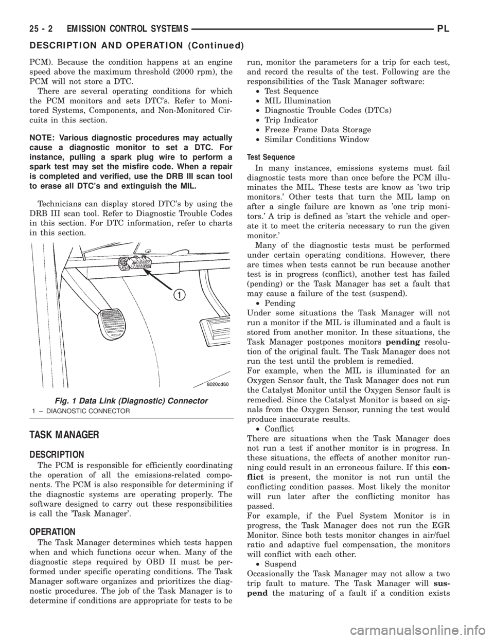
Technicians can display stored DTC's by using the
DRB III scan tool. Refer to Diagnostic Trouble Codes
in this section. For DTC information, refer to charts
in this section.
TASK MANAGER
DESCRIPTION
The PCM is responsible for efficiently coordinating
the operation of all the emissions-related compo-
nents. The PCM is also responsible for determining if
the diagnostic systems are operating properly. The
software designed to carry out these responsibilities
is call the 'Task Manager'.
OPERATION
The Task Manager determines which tests happen
when and which functions occur when. Many of the
diagnostic steps required by OBD II must be per-
formed under specific operating conditions. The Task
Manager software organizes and prioritizes the diag-
nostic procedures. The job of the Task Manager is to
determine if conditions are appropriate for tests to berun, monitor the parameters for a trip for each test,
and record the results of the test. Following are the
responsibilities of the Task Manager software:
²Test Sequence
²MIL Illumination
²Diagnostic Trouble Codes (DTCs)
²Trip Indicator
²Freeze Frame Data Storage
²Similar Conditions Window
Test Sequence
In many instances, emissions systems must fail
diagnostic tests more than once before the PCM illu-
minates the MIL. These tests are know as 'two trip
monitors.' Other tests that turn the MIL lamp on
after a single failure are known as 'one trip moni-
tors.' A trip is defined as 'start the vehicle and oper-
ate it to meet the criteria necessary to run the given
monitor.'
Many of the diagnostic tests must be performed
under certain operating conditions. However, there
are times when tests cannot be run because another
test is in progress (conflict), another test has failed
(pending) or the Task Manager has set a fault that
may cause a failure of the test (suspend).
²Pending
Under some situations the Task Manager will not
run a monitor if the MIL is illuminated and a fault is
stored from another monitor. In these situations, the
Task Manager postpones monitorspendingresolu-
tion of the original fault. The Task Manager does not
run the test until the problem is remedied.
For example, when the MIL is illuminated for an
Oxygen Sensor fault, the Task Manager does not run
the Catalyst Monitor until the Oxygen Sensor fault is
remedied. Since the Catalyst Monitor is based on sig-
nals from the Oxygen Sensor, running the test would
produce inaccurate results.
²Conflict
There are situations when the Task Manager does
not run a test if another monitor is in progress. In
these situations, the effects of another monitor run-
ning could result in an erroneous failure. If thiscon-
flictis present, the monitor is not run until the
conflicting condition passes. Most likely the monitor
will run later after the conflicting monitor has
passed.
For example, if the Fuel System Monitor is in
progress, the Task Manager does not run the EGR
Monitor. Since both tests monitor changes in air/fuel
ratio and adaptive fuel compensation, the monitors
will conflict with each other.
²Suspend
Occasionally the Task Manager may not allow a two
trip fault to mature. The Task Manager willsus-
pendthe maturing of a fault if a condition exists
Fig. 1 Data Link (Diagnostic) Connector
1 ± DIAGNOSTIC CONNECTOR
25 - 2 EMISSION CONTROL SYSTEMSPL
DESCRIPTION AND OPERATION (Continued)
Page 1090 of 1285
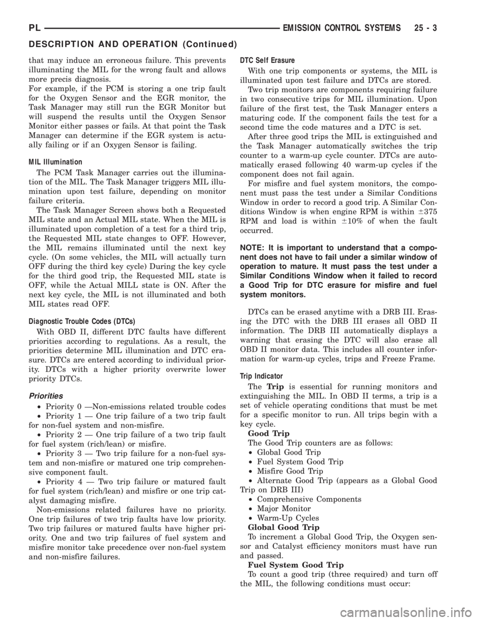
that may induce an erroneous failure. This prevents
illuminating the MIL for the wrong fault and allows
more precis diagnosis.
For example, if the PCM is storing a one trip fault
for the Oxygen Sensor and the EGR monitor, the
Task Manager may still run the EGR Monitor but
will suspend the results until the Oxygen Sensor
Monitor either passes or fails. At that point the Task
Manager can determine if the EGR system is actu-
ally failing or if an Oxygen Sensor is failing.
MIL Illumination
The PCM Task Manager carries out the illumina-
tion of the MIL. The Task Manager triggers MIL illu-
mination upon test failure, depending on monitor
failure criteria.
The Task Manager Screen shows both a Requested
MIL state and an Actual MIL state. When the MIL is
illuminated upon completion of a test for a third trip,
the Requested MIL state changes to OFF. However,
the MIL remains illuminated until the next key
cycle. (On some vehicles, the MIL will actually turn
OFF during the third key cycle) During the key cycle
for the third good trip, the Requested MIL state is
OFF, while the Actual MILL state is ON. After the
next key cycle, the MIL is not illuminated and both
MIL states read OFF.
Diagnostic Trouble Codes (DTCs)
With OBD II, different DTC faults have different
priorities according to regulations. As a result, the
priorities determine MIL illumination and DTC era-
sure. DTCs are entered according to individual prior-
ity. DTCs with a higher priority overwrite lower
priority DTCs.
Priorities
²Priority 0 ÐNon-emissions related trouble codes
²Priority 1 Ð One trip failure of a two trip fault
for non-fuel system and non-misfire.
²Priority 2 Ð One trip failure of a two trip fault
for fuel system (rich/lean) or misfire.
²Priority3ÐTwotrip failure for a non-fuel sys-
tem and non-misfire or matured one trip comprehen-
sive component fault.
²Priority4ÐTwotrip failure or matured fault
for fuel system (rich/lean) and misfire or one trip cat-
alyst damaging misfire.
Non-emissions related failures have no priority.
One trip failures of two trip faults have low priority.
Two trip failures or matured faults have higher pri-
ority. One and two trip failures of fuel system and
misfire monitor take precedence over non-fuel system
and non-misfire failures.DTC Self Erasure
With one trip components or systems, the MIL is
illuminated upon test failure and DTCs are stored.
Two trip monitors are components requiring failure
in two consecutive trips for MIL illumination. Upon
failure of the first test, the Task Manager enters a
maturing code. If the component fails the test for a
second time the code matures and a DTC is set.
After three good trips the MIL is extinguished and
the Task Manager automatically switches the trip
counter to a warm-up cycle counter. DTCs are auto-
matically erased following 40 warm-up cycles if the
component does not fail again.
For misfire and fuel system monitors, the compo-
nent must pass the test under a Similar Conditions
Window in order to record a good trip. A Similar Con-
ditions Window is when engine RPM is within6375
RPM and load is within610% of when the fault
occurred.
NOTE: It is important to understand that a compo-
nent does not have to fail under a similar window of
operation to mature. It must pass the test under a
Similar Conditions Window when it failed to record
a Good Trip for DTC erasure for misfire and fuel
system monitors.
DTCs can be erased anytime with a DRB III. Eras-
ing the DTC with the DRB III erases all OBD II
information. The DRB III automatically displays a
warning that erasing the DTC will also erase all
OBD II monitor data. This includes all counter infor-
mation for warm-up cycles, trips and Freeze Frame.
Trip Indicator
TheTripis essential for running monitors and
extinguishing the MIL. In OBD II terms, a trip is a
set of vehicle operating conditions that must be met
for a specific monitor to run. All trips begin with a
key cycle.
Good Trip
The Good Trip counters are as follows:
²Global Good Trip
²Fuel System Good Trip
²Misfire Good Trip
²Alternate Good Trip (appears as a Global Good
Trip on DRB III)
²Comprehensive Components
²Major Monitor
²Warm-Up Cycles
Global Good Trip
To increment a Global Good Trip, the Oxygen sen-
sor and Catalyst efficiency monitors must have run
and passed.
Fuel System Good Trip
To count a good trip (three required) and turn off
the MIL, the following conditions must occur:
PLEMISSION CONTROL SYSTEMS 25 - 3
DESCRIPTION AND OPERATION (Continued)
Page 1097 of 1285
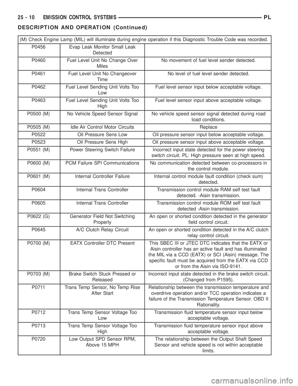
(M) Check Engine Lamp (MIL) will illuminate during engine operation if this Diagnostic Trouble Code was recorded.
P0456 Evap Leak Monitor Small Leak
Detected
P0460 Fuel Level Unit No Change Over
MilesNo movement of fuel level sender detected.
P0461 Fuel Level Unit No Changeover
TimeNo level of fuel level sender detected.
P0462 Fuel Level Sending Unit Volts Too
LowFuel level sensor input below acceptable voltage.
P0463 Fuel Level Sending Unit Volts Too
HighFuel level sensor input above acceptable voltage.
P0500 (M) No Vehicle Speed Sensor Signal No vehicle speed sensor signal detected during road
load conditions.
P0505 (M) Idle Air Control Motor Circuits Replace
P0522 Oil Pressure Sens Low Oil pressure sensor input below acceptable voltage.
P0523 Oil Pressure Sens High Oil pressure sensor input above acceptable voltage.
P0551 (M) Power Steering Switch Failure Incorrect input state detected for the power steering
switch circuit. PL: High pressure seen at high speed.
P0600 (M) PCM Failure SPI Communications No communication detected between co-processors in
the control module.
P0601 (M) Internal Controller Failure Internal control module fault condition (check sum)
detected.
P0604 Internal Trans Controller Transmission control module RAM self test fault
detected. -Aisin transmission.
P0605 Internal Trans Controller Transmission control module ROM self test fault
detected -Aisin transmission.
P0622 (G) Generator Field Not Switching
ProperlyAn open or shorted condition detected in the generator
field control circuit.
P0645 A/C Clutch Relay Circuit An open or shorted condition detected in the A/C clutch
relay control circuit.
P0700 (M) EATX Controller DTC Present This SBEC III or JTEC DTC indicates that the EATX or
Aisin controller has an active fault and has illuminated
the MIL via a CCD (EATX) or SCI (Aisin) message. The
specific fault must be acquired from the EATX via CCD
or from the Aisin via ISO-9141.
P0703 (M) Brake Switch Stuck Pressed or
ReleasedIncorrect input state detected in the brake switch circuit.
(Changed from P1595).
P0711 Trans Temp Sensor, No Temp Rise
After StartRelationship between the transmission temperature and
overdrive operation and/or TCC operation indicates a
failure of the Transmission Temperature Sensor. OBD II
Rationality.
P0712 Trans Temp Sensor Voltage Too
LowTransmission fluid temperature sensor input below
acceptable voltage.
P0713 Trans Temp Sensor Voltage Too
HighTransmission fluid temperature sensor input above
acceptable voltage.
P0720 Low Output SPD Sensor RPM,
Above 15 MPHThe relationship between the Output Shaft Speed
Sensor and vehicle speed is not within acceptable
limits.
25 - 10 EMISSION CONTROL SYSTEMSPL
DESCRIPTION AND OPERATION (Continued)