suction air leak DODGE NEON 2000 Service Repair Manual
[x] Cancel search | Manufacturer: DODGE, Model Year: 2000, Model line: NEON, Model: DODGE NEON 2000Pages: 1285, PDF Size: 29.42 MB
Page 189 of 1285
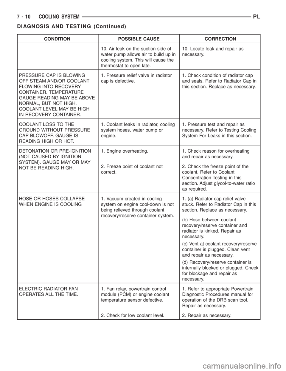
CONDITION POSSIBLE CAUSE CORRECTION
10. Air leak on the suction side of
water pump allows air to build up in
cooling system. This will cause the
thermostat to open late.10. Locate leak and repair as
necessary.
PRESSURE CAP IS BLOWING
OFF STEAM AND/OR COOLANT
FLOWING INTO RECOVERY
CONTAINER. TEMPERATURE
GAUGE READING MAY BE ABOVE
NORMAL, BUT NOT HIGH.
COOLANT LEVEL MAY BE HIGH
IN RECOVERY CONTAINER.1. Pressure relief valve in radiator
cap is defective.1. Check condition of radiator cap
and seals. Refer to Radiator Cap in
this section. Replace as necessary.
COOLANT LOSS TO THE
GROUND WITHOUT PRESSURE
CAP BLOWOFF. GAUGE IS
READING HIGH OR HOT.1. Coolant leaks in radiator, cooling
system hoses, water pump or
engine.1. Pressure test and repair as
necessary. Refer to Testing Cooling
System For Leaks in this section.
DETONATION OR PRE-IGNITION
(NOT CAUSED BY IGNITION
SYSTEM). GAUGE MAY OR MAY
NOT BE READING HIGH.1. Engine overheating. 1. Check reason for overheating
and repair as necessary.
2. Freeze point of coolant not
correct.2. Check the freeze point of the
coolant. Refer to Coolant
Concentration Testing in this
section. Adjust glycol-to-water ratio
as required.
HOSE OR HOSES COLLAPSE
WHEN ENGINE IS COOLING1. Vacuum created in cooling
system on engine cool-down is not
being relieved through coolant
recovery/reserve container system.1. (a) Radiator cap relief valve
stuck. Refer to Radiator Cap in this
section. Replace as necessary.
(b) Hose between coolant
recovery/reserve container and
radiator is kinked. Repair as
necessary.
(c) Vent at coolant recovery/reserve
container is plugged. Clean vent
and repair as necessary.
(d) Recovery/reserve container is
internally blocked or plugged. Check
for blockage and repair as
necessary.
ELECTRIC RADIATOR FAN
OPERATES ALL THE TIME.1. Fan relay, powertrain control
module (PCM) or engine coolant
temperature sensor defective.1. Refer to appropriate Powertrain
Diagnostic Procedures manual for
operation of the DRB scan tool.
Repair as necessary.
2. Check for low coolant level. 2. Repair as necessary.
7 - 10 COOLING SYSTEMPL
DIAGNOSIS AND TESTING (Continued)
Page 736 of 1285
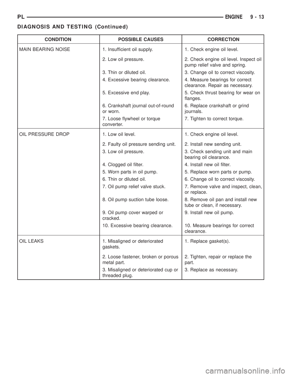
CONDITION POSSIBLE CAUSES CORRECTION
MAIN BEARING NOISE 1. Insufficient oil supply. 1. Check engine oil level.
2. Low oil pressure. 2. Check engine oil level. Inspect oil
pump relief valve and spring.
3. Thin or diluted oil. 3. Change oil to correct viscosity.
4. Excessive bearing clearance. 4. Measure bearings for correct
clearance. Repair as necessary.
5. Excessive end play. 5. Check thrust bearing for wear on
flanges.
6. Crankshaft journal out-of-round
or worn.6. Replace crankshaft or grind
journals.
7. Loose flywheel or torque
converter.7. Tighten to correct torque.
OIL PRESSURE DROP 1. Low oil level. 1. Check engine oil level.
2. Faulty oil pressure sending unit. 2. Install new sending unit.
3. Low oil pressure. 3. Check sending unit and main
bearing oil clearance.
4. Clogged oil filter. 4. Install new oil filter.
5. Worn parts in oil pump. 5. Replace worn parts or pump.
6. Thin or diluted oil. 6. Change oil to correct viscosity.
7. Oil pump relief valve stuck. 7. Remove valve and inspect, clean,
or replace.
8. Oil pump suction tube loose. 8. Remove oil pan and install new
tube or clean, if necessary.
9. Oil pump cover warped or
cracked.9. Install new oil pump.
10. Excessive bearing clearance. 10. Measure bearings for correct
clearance.
OIL LEAKS 1. Misaligned or deteriorated
gaskets.1. Replace gasket(s).
2. Loose fastener, broken or porous
metal part.2. Tighten, repair or replace the
part.
3. Misaligned or deteriorated cup or
threaded plug.3. Replace as necessary.
PLENGINE 9 - 13
DIAGNOSIS AND TESTING (Continued)
Page 974 of 1285
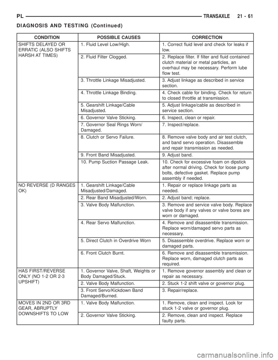
CONDITION POSSIBLE CAUSES CORRECTION
SHIFTS DELAYED OR
ERRATIC (ALSO SHIFTS
HARSH AT TIMES)1. Fluid Level Low/High. 1. Correct fluid level and check for leaks if
low.
2. Fluid Filter Clogged. 2. Replace filter. If filter and fluid contained
clutch material or metal particles, an
overhaul may be necessary. Perform lube
flow test.
3. Throttle Linkage Misadjusted. 3. Adjust linkage as described in service
section.
4. Throttle Linkage Binding. 4. Check cable for binding. Check for return
to closed throttle at transmission.
5. Gearshift Linkage/Cable
Misadjusted.5. Adjust linkage/cable as described in
service section.
6. Governor Valve Sticking. 6. Inspect, clean or repair.
7. Governor Seal Rings Worn/
Damaged.7. Inspect/replace.
8. Clutch or Servo Failure. 8. Remove valve body and air test clutch,
and band servo operation. Disassemble
and repair transmission as needed.
9. Front Band Misadjusted. 9. Adjust band.
10. Pump Suction Passage Leak. 10. Check for excessive foam on dipstick
after normal driving. Check for loose pump
bolts, defective gasket. Replace pump
assembly if needed.
NO REVERSE (D RANGES
OK)1. Gearshift Linkage/Cable
Misadjusted/Damaged.1. Repair or replace linkage parts as
needed.
2. Rear Band Misadjusted/Worn. 2. Adjust band; replace.
3. Valve Body Malfunction. 3. Remove and service valve body. Replace
valve body if any valves or valve bores are
worn or damaged.
4. Rear Servo Malfunction. 4. Remove and disassemble transmission.
Replace worn/damaged servo parts as
necessary.
5. Direct Clutch in Overdrive Worn 5. Disassemble overdrive. Replace worn or
damaged parts.
6. Front Clutch Burnt. 6. Remove and disassemble transmission.
Replace worn, damaged clutch parts as
required.
HAS FIRST/REVERSE
ONLY (NO 1-2 OR 2-3
UPSHIFT)1. Governor Valve, Shaft, Weights or
Body Damaged/Stuck.1. Remove governor assembly and clean or
repair as necessary.
2. Valve Body Malfunction. 2. Stuck 1-2 shift valve or governor plug.
3. Front Servo/Kickdown Band
Damaged/Burned.3. Repair/replace.
MOVES IN 2ND OR 3RD
GEAR, ABRUPTLY
DOWNSHIFTS TO LOW1. Valve Body Malfunction. 1. Remove, clean and inspect. Look for
stuck 1-2 valve or governor plug.
2. Governor Valve Sticking. 2. Remove, clean and inspect. Replace
faulty parts.
PLTRANSAXLE 21 - 61
DIAGNOSIS AND TESTING (Continued)
Page 982 of 1285
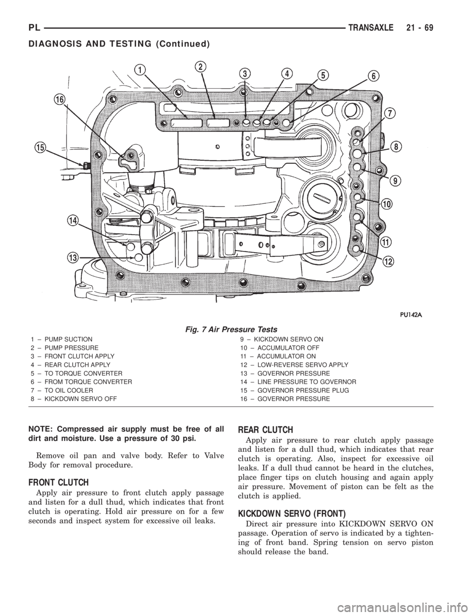
NOTE: Compressed air supply must be free of all
dirt and moisture. Use a pressure of 30 psi.
Remove oil pan and valve body. Refer to Valve
Body for removal procedure.
FRONT CLUTCH
Apply air pressure to front clutch apply passage
and listen for a dull thud, which indicates that front
clutch is operating. Hold air pressure on for a few
seconds and inspect system for excessive oil leaks.
REAR CLUTCH
Apply air pressure to rear clutch apply passage
and listen for a dull thud, which indicates that rear
clutch is operating. Also, inspect for excessive oil
leaks. If a dull thud cannot be heard in the clutches,
place finger tips on clutch housing and again apply
air pressure. Movement of piston can be felt as the
clutch is applied.
KICKDOWN SERVO (FRONT)
Direct air pressure into KICKDOWN SERVO ON
passage. Operation of servo is indicated by a tighten-
ing of front band. Spring tension on servo piston
should release the band.
Fig. 7 Air Pressure Tests
1 ± PUMP SUCTION
2 ± PUMP PRESSURE
3 ± FRONT CLUTCH APPLY
4 ± REAR CLUTCH APPLY
5 ± TO TORQUE CONVERTER
6 ± FROM TORQUE CONVERTER
7 ± TO OIL COOLER
8 ± KICKDOWN SERVO OFF9 ± KICKDOWN SERVO ON
10 ± ACCUMULATOR OFF
11 ± ACCUMULATOR ON
12 ± LOW-REVERSE SERVO APPLY
13 ± GOVERNOR PRESSURE
14 ± LINE PRESSURE TO GOVERNOR
15 ± GOVERNOR PRESSURE PLUG
16 ± GOVERNOR PRESSURE
PLTRANSAXLE 21 - 69
DIAGNOSIS AND TESTING (Continued)
Page 1232 of 1285
HEATING AND AIR CONDITIONING
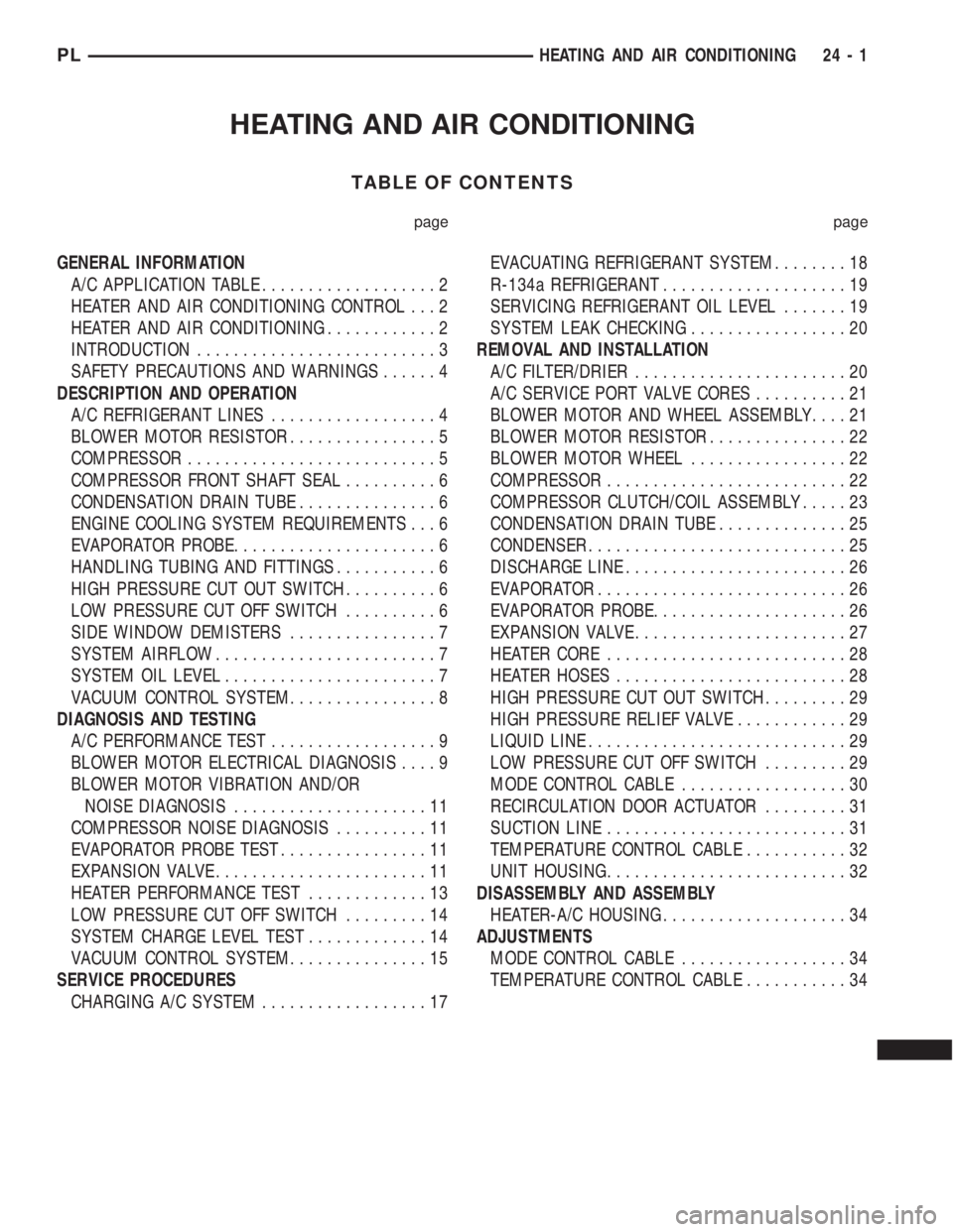
TABLE OF CONTENTS
page page
GENERAL INFORMATION
A/C APPLICATION TABLE...................2
HEATER AND AIR CONDITIONING CONTROL...2
HEATER AND AIR CONDITIONING............2
INTRODUCTION..........................3
SAFETY PRECAUTIONS AND WARNINGS......4
DESCRIPTION AND OPERATION
A/C REFRIGERANT LINES..................4
BLOWER MOTOR RESISTOR................5
COMPRESSOR...........................5
COMPRESSOR FRONT SHAFT SEAL..........6
CONDENSATION DRAIN TUBE...............6
ENGINE COOLING SYSTEM REQUIREMENTS...6
EVAPORATOR PROBE......................6
HANDLING TUBING AND FITTINGS...........6
HIGH PRESSURE CUT OUT SWITCH..........6
LOW PRESSURE CUT OFF SWITCH..........6
SIDE WINDOW DEMISTERS................7
SYSTEM AIRFLOW........................7
SYSTEM OIL LEVEL.......................7
VACUUM CONTROL SYSTEM................8
DIAGNOSIS AND TESTING
A/C PERFORMANCE TEST..................9
BLOWER MOTOR ELECTRICAL DIAGNOSIS....9
BLOWER MOTOR VIBRATION AND/OR
NOISE DIAGNOSIS.....................11
COMPRESSOR NOISE DIAGNOSIS..........11
EVAPORATOR PROBE TEST................11
EXPANSION VALVE.......................11
HEATER PERFORMANCE TEST.............13
LOW PRESSURE CUT OFF SWITCH.........14
SYSTEM CHARGE LEVEL TEST.............14
VACUUM CONTROL SYSTEM...............15
SERVICE PROCEDURES
CHARGING A/C SYSTEM..................17EVACUATING REFRIGERANT SYSTEM........18
R-134a REFRIGERANT....................19
SERVICING REFRIGERANT OIL LEVEL.......19
SYSTEM LEAK CHECKING.................20
REMOVAL AND INSTALLATION
A/C FILTER/DRIER.......................20
A/C SERVICE PORT VALVE CORES..........21
BLOWER MOTOR AND WHEEL ASSEMBLY....21
BLOWER MOTOR RESISTOR...............22
BLOWER MOTOR WHEEL.................22
COMPRESSOR..........................22
COMPRESSOR CLUTCH/COIL ASSEMBLY.....23
CONDENSATION DRAIN TUBE..............25
CONDENSER............................25
DISCHARGE LINE........................26
EVAPORATOR...........................26
EVAPORATOR PROBE.....................26
EXPANSION VALVE.......................27
HEATER CORE..........................28
HEATER HOSES.........................28
HIGH PRESSURE CUT OUT SWITCH.........29
HIGH PRESSURE RELIEF VALVE............29
LIQUID LINE............................29
LOW PRESSURE CUT OFF SWITCH.........29
MODE CONTROL CABLE..................30
RECIRCULATION DOOR ACTUATOR.........31
SUCTION LINE..........................31
TEMPERATURE CONTROL CABLE...........32
UNIT HOUSING..........................32
DISASSEMBLY AND ASSEMBLY
HEATER-A/C HOUSING....................34
ADJUSTMENTS
MODE CONTROL CABLE..................34
TEMPERATURE CONTROL CABLE...........34
PLHEATING AND AIR CONDITIONING 24 - 1
Page 1235 of 1285
SAFETY PRECAUTIONS AND WARNINGS
WARNING: WEAR EYE PROTECTION WHEN SER-
VICING THE AIR CONDITIONING REFRIGERANT
SYSTEM. SERIOUS EYE INJURY CAN RESULT
FROM EYE CONTACT WITH REFRIGERANT. IF EYE
CONTACT IS MADE, SEEK MEDICAL ATTENTION
IMMEDIATELY.
DO NOT EXPOSE REFRIGERANT TO OPEN
FLAME. POISONOUS GAS IS CREATED WHEN
REFRIGERANT IS BURNED. AN ELECTRONIC TYPE
LEAK DETECTOR IS RECOMMENDED.
LARGE AMOUNTS OF REFRIGERANT RELEASED
IN A CLOSED WORK AREA WILL DISPLACE THE
OXYGEN AND CAUSE SUFFOCATION.
THE EVAPORATION RATE OF REFRIGERANT AT
AVERAGE TEMPERATURE AND ALTITUDE IS
EXTREMELY HIGH. AS A RESULT, ANYTHING THAT
COMES IN CONTACT WITH THE REFRIGERANT
WILL FREEZE. ALWAYS PROTECT SKIN OR DELI-
CATE OBJECTS FROM DIRECT CONTACT WITH
REFRIGERANT. R-134a SERVICE EQUIPMENT OR
VEHICLE A/C SYSTEM SHOULD NOT BE PRES-
SURE TESTED OR LEAK TESTED WITH COM-
PRESSED AIR.
SOME MIXTURES OF AIR and R-134a HAVE BEEN
SHOWN TO BE COMBUSTIBLE AT ELEVATED
PRESSURES. THESE MIXTURES ARE POTENTIALLY
DANGEROUS AND MAY RESULT IN FIRE OR
EXPLOSION CAUSING INJURY OR PROPERTY
DAMAGE.
ANTIFREEZE IS AN ETHYLENE GLYCOL BASE
COOLANT AND IS HARMFUL IF SWALLOWED OR
INHALED. SEEK MEDICAL ATTENTION IMMEDI-
ATELY IF SWALLOWED OR INHALED. DO NOT
STORE IN OPEN OR UNMARKED CONTAINERS.
WASH SKIN AND CLOTHING THOROUGHLY AFTER
COMING IN CONTACT WITH ETHYLENE GLYCOL.
KEEP OUT OF REACH OF CHILDREN AND PETS.
DO NOT OPEN A COOLING SYSTEM WHEN THE
ENGINE IS AT RUNNING TEMPERATURE. PER-
SONAL INJURY CAN RESULT.
CAUTION: The engine cooling system is designed
to develop internal pressure of 97 to 123 kPa (14 to
18 psi). Allow the vehicle to cool a minimum of 15
minutes before opening the cooling system. Refer
to Group 7, Cooling System.
DESCRIPTION AND OPERATION
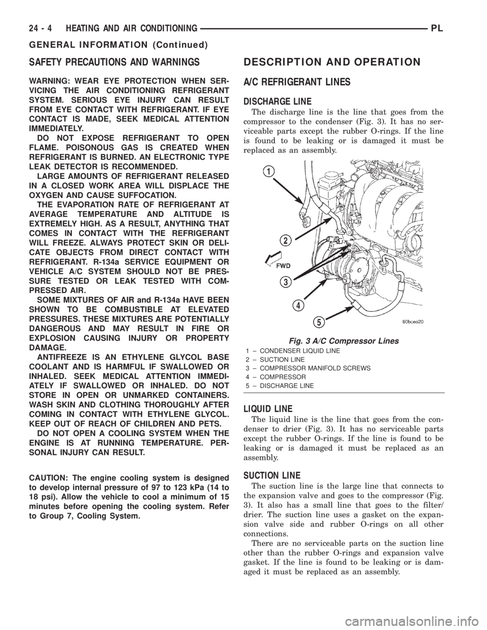
A/C REFRIGERANT LINES
DISCHARGE LINE
The discharge line is the line that goes from the
compressor to the condenser (Fig. 3). It has no ser-
viceable parts except the rubber O-rings. If the line
is found to be leaking or is damaged it must be
replaced as an assembly.
LIQUID LINE
The liquid line is the line that goes from the con-
denser to drier (Fig. 3). It has no serviceable parts
except the rubber O-rings. If the line is found to be
leaking or is damaged it must be replaced as an
assembly.
SUCTION LINE
The suction line is the large line that connects to
the expansion valve and goes to the compressor (Fig.
3). It also has a small line that goes to the filter/
drier. The suction line uses a gasket on the expan-
sion valve side and rubber O-rings on all other
connections.
There are no serviceable parts on the suction line
other than the rubber O-rings and expansion valve
gasket. If the line is found to be leaking or is dam-
aged it must be replaced as an assembly.
Fig. 3 A/C Compressor Lines
1 ± CONDENSER LIQUID LINE
2 ± SUCTION LINE
3 ± COMPRESSOR MANIFOLD SCREWS
4 ± COMPRESSOR
5 ± DISCHARGE LINE
24 - 4 HEATING AND AIR CONDITIONINGPL
GENERAL INFORMATION (Continued)
Page 1237 of 1285
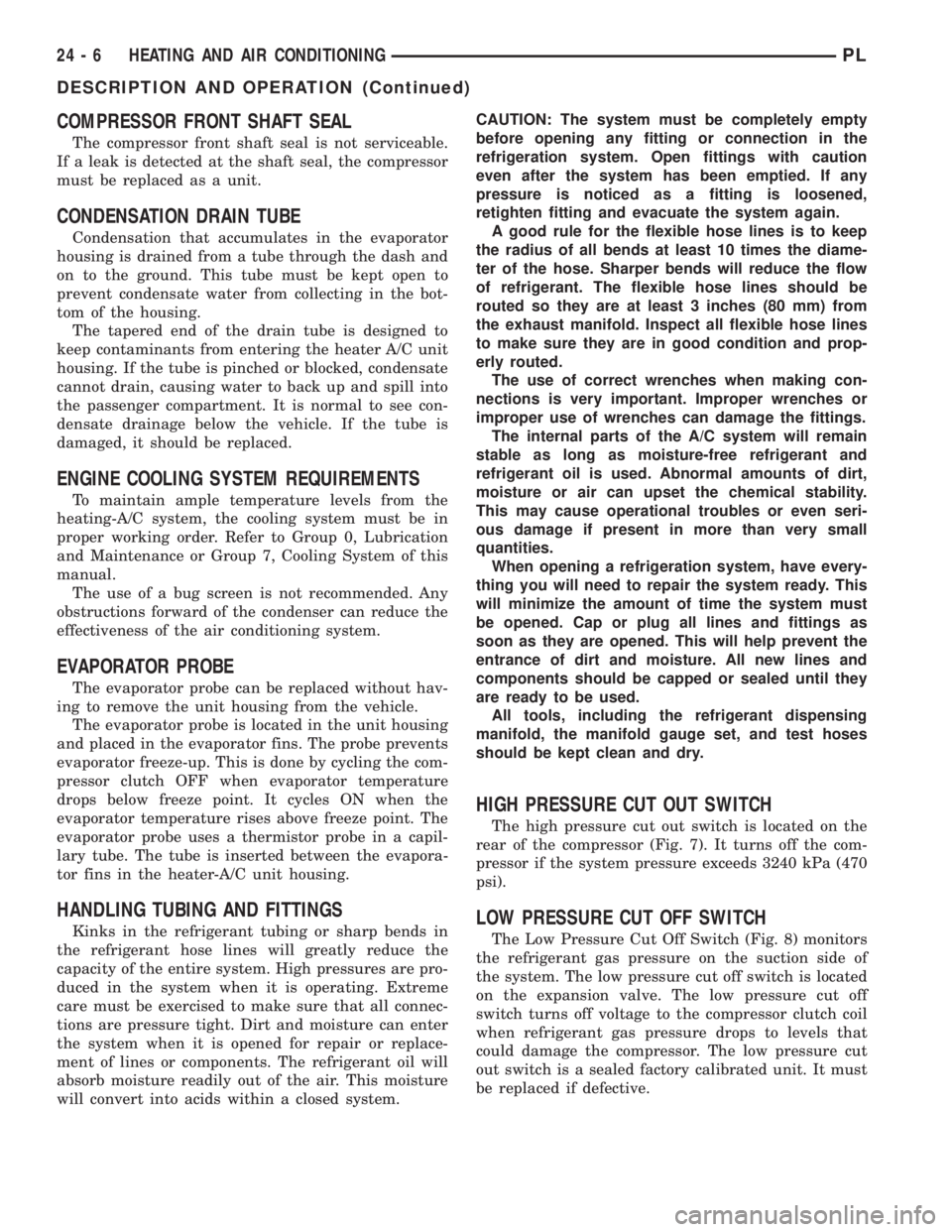
COMPRESSOR FRONT SHAFT SEAL
The compressor front shaft seal is not serviceable.
If a leak is detected at the shaft seal, the compressor
must be replaced as a unit.
CONDENSATION DRAIN TUBE
Condensation that accumulates in the evaporator
housing is drained from a tube through the dash and
on to the ground. This tube must be kept open to
prevent condensate water from collecting in the bot-
tom of the housing.
The tapered end of the drain tube is designed to
keep contaminants from entering the heater A/C unit
housing. If the tube is pinched or blocked, condensate
cannot drain, causing water to back up and spill into
the passenger compartment. It is normal to see con-
densate drainage below the vehicle. If the tube is
damaged, it should be replaced.
ENGINE COOLING SYSTEM REQUIREMENTS
To maintain ample temperature levels from the
heating-A/C system, the cooling system must be in
proper working order. Refer to Group 0, Lubrication
and Maintenance or Group 7, Cooling System of this
manual.
The use of a bug screen is not recommended. Any
obstructions forward of the condenser can reduce the
effectiveness of the air conditioning system.
EVAPORATOR PROBE
The evaporator probe can be replaced without hav-
ing to remove the unit housing from the vehicle.
The evaporator probe is located in the unit housing
and placed in the evaporator fins. The probe prevents
evaporator freeze-up. This is done by cycling the com-
pressor clutch OFF when evaporator temperature
drops below freeze point. It cycles ON when the
evaporator temperature rises above freeze point. The
evaporator probe uses a thermistor probe in a capil-
lary tube. The tube is inserted between the evapora-
tor fins in the heater-A/C unit housing.
HANDLING TUBING AND FITTINGS
Kinks in the refrigerant tubing or sharp bends in
the refrigerant hose lines will greatly reduce the
capacity of the entire system. High pressures are pro-
duced in the system when it is operating. Extreme
care must be exercised to make sure that all connec-
tions are pressure tight. Dirt and moisture can enter
the system when it is opened for repair or replace-
ment of lines or components. The refrigerant oil will
absorb moisture readily out of the air. This moisture
will convert into acids within a closed system.CAUTION: The system must be completely empty
before opening any fitting or connection in the
refrigeration system. Open fittings with caution
even after the system has been emptied. If any
pressure is noticed as a fitting is loosened,
retighten fitting and evacuate the system again.
A good rule for the flexible hose lines is to keep
the radius of all bends at least 10 times the diame-
ter of the hose. Sharper bends will reduce the flow
of refrigerant. The flexible hose lines should be
routed so they are at least 3 inches (80 mm) from
the exhaust manifold. Inspect all flexible hose lines
to make sure they are in good condition and prop-
erly routed.
The use of correct wrenches when making con-
nections is very important. Improper wrenches or
improper use of wrenches can damage the fittings.
The internal parts of the A/C system will remain
stable as long as moisture-free refrigerant and
refrigerant oil is used. Abnormal amounts of dirt,
moisture or air can upset the chemical stability.
This may cause operational troubles or even seri-
ous damage if present in more than very small
quantities.
When opening a refrigeration system, have every-
thing you will need to repair the system ready. This
will minimize the amount of time the system must
be opened. Cap or plug all lines and fittings as
soon as they are opened. This will help prevent the
entrance of dirt and moisture. All new lines and
components should be capped or sealed until they
are ready to be used.
All tools, including the refrigerant dispensing
manifold, the manifold gauge set, and test hoses
should be kept clean and dry.
HIGH PRESSURE CUT OUT SWITCH
The high pressure cut out switch is located on the
rear of the compressor (Fig. 7). It turns off the com-
pressor if the system pressure exceeds 3240 kPa (470
psi).
LOW PRESSURE CUT OFF SWITCH
The Low Pressure Cut Off Switch (Fig. 8) monitors
the refrigerant gas pressure on the suction side of
the system. The low pressure cut off switch is located
on the expansion valve. The low pressure cut off
switch turns off voltage to the compressor clutch coil
when refrigerant gas pressure drops to levels that
could damage the compressor. The low pressure cut
out switch is a sealed factory calibrated unit. It must
be replaced if defective.
24 - 6 HEATING AND AIR CONDITIONINGPL
DESCRIPTION AND OPERATION (Continued)
Page 1239 of 1285
NOTE: The oil used in the compressor is ND8 PAG
R-134a refrigerant oil. Only refrigerant oil of the
same type should be used to service the system.
Do not use any other oil. The oil container should
be kept tightly capped until it is ready for use.
Tightly cap afterwards to prevent contamination
from dirt and moisture. Refrigerant oil will quickly
absorb any moisture it comes in contact with. Spe-
cial effort must be used to keep all R-134a system
components moisture-free. Moisture in the oil is
very difficult to remove and will cause a reliability
problem with the compressor.
It will not be necessary to check oil level in the
compressor or to add oil unless there has been an oil
loss. Oil loss at a leak point will be evident by the
presence of a wet, shiny surface around the leak.
REFRIGERANT OIL LEVEL CHECK
When an air conditioning system is first assem-
bled, all components (except the compressor) are
refrigerant oil free. After the system has been
charged with R-134a refrigerant and operated, the oil
in the compressor is dispersed through the lines and
components. The evaporator, condenser, and filter-
drier will retain a significant amount of oil, refer to
the Refrigerant Oil Capacities chart. When a compo-
nent is replaced, the specified amount of refrigerant
oil must be added. When the compressor is replaced,
the amount of oil that is retained in the rest of the
system must be drained from the replacement com-
pressor. When a line or component has ruptured and
oil has escaped, the compressor should be removed
and drained. The filter-drier must be replaced along
with the ruptured part. The oil capacity of the sys-
tem, minus the amount of oil still in the remaining
components, can be measured and poured into the
suction port of the compressor.
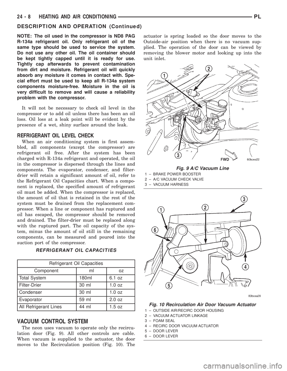
VACUUM CONTROL SYSTEM
The neon uses vacuum to operate only the recircu-
lation door (Fig. 9). All other controls are cable.
When vacuum is supplied to the actuator, the door
moves to the Recirculation position (Fig. 10). Theactuator is spring loaded so the door moves to the
Outside-air position when there is no vacuum sup-
plied. The operation of the door can be viewed by
removing the blower motor and looking up into the
unit inlet.
REFRIGERANT OIL CAPACITIES
Refrigerant Oil Capacities
Component ml oz
Total System 180ml 6.1 oz
Filter-Drier 30 ml 1.0 oz
Condenser 30 ml 1.0 oz
Evaporator 59 ml 2.0 oz
All Refrigerant Lines 44 ml 1.5 oz
Fig. 9 A/C Vacuum Line
1 ± BRAKE POWER BOOSTER
2 ± A/C VACUUM CHECK VALVE
3 ± VACUUM HARNESS
Fig. 10 Recirculation Air Door Vacuum Actuator
1 ± OUTSIDE AIR/RECIRC DOOR HOUSING
2 ± VACUUM ACTUATOR LINKAGE
3 ± FOAM SEAL
4 ± RECIRC DOOR VACUUM ACTUATOR
5 ± DOOR LEVER
6 ± DOOR LEVER
24 - 8 HEATING AND AIR CONDITIONINGPL
DESCRIPTION AND OPERATION (Continued)
Page 1249 of 1285
CAUTION: Do not overcharge refrigerant system,
as excessive compressor head pressure can cause
noise and system failure.
After the system has been tested for leaks and
evacuated, a refrigerant (R-134a) charge can be
injected into the system.
NOTE: When connecting the service equipment
coupling to the line fitting, verify that the valve of
the coupling is fully closed. This will reduce the
amount of effort required to make the connection.
(1) If using a separate vacuum pump close all
valves before disconnecting pump. Connect manifold
gauge set to the A/C service ports (Fig. 16).
NOTE: The air conditioning system in this vehicle
holds (27 oz. or 1.69 lbs.) of R-134a refrigerant.
(2) Measure refrigerant (refer to capacities). Refer
to the instructions provided with the equipment
being used.
(3) Verify engine is shut off. Open the suction and
discharge valves. Open the charge valve to allow the
refrigerant to flow into the system. When the trans-
fer of refrigerant has stopped, close the suction and
discharge valve.
(4) If all of the charge did not transfer from the
dispensing device, put vehicle controls into the fol-
lowing mode:
²Automatic transaxle in park or manual tran-
saxle in neutral
²Engine idling at 700 rpm
²A/C control set in 100 percent outside air
²Panel mode
²Blower motor ON high speed
²Vehicle windows closed
If the A/C compressor does not engage, test the
compressor clutch control circuit and correct any fail-
ure. Refer to Group 8W, Wiring Diagrams.
(5) Open the suction valve to allow the remaining
refrigerant to transfer to the system.
WARNING: TAKE CARE NOT TO OPEN THE DIS-
CHARGE (HIGH-PRESSURE) VALVE AT THIS TIME.
(6) Close all valves and test the A/C system perfor-
mance.
(7) Disconnect the charging station or manifold
gauge set. Install the service port caps.
EVACUATING REFRIGERANT SYSTEM
NOTE: Special effort must be used to prevent mois-
ture from entering the A/C system oil. Moisture in
the oil is very difficult to remove and will cause a
reliability problem with the compressor.If a compressor designed to use R-134a refrigerant
is left open to the atmosphere for an extended period
of time. It is recommended that the refrigerant oil be
drained and replaced with new oil or a new compres-
sor be used. This will eliminate the possibility of con-
taminating the refrigerant system.
If the refrigerant system has been open to the
atmosphere, it must be evacuated before the system
can be filled. Moisture and air mixed with the refrig-
erant will raise the compressor head pressure above
acceptable operating levels. This will reduce the per-
formance of the air conditioner and damage the com-
pressor. Moisture will boil at near room temperature
when exposed to vacuum. To evacuate the refrigerant
system:
NOTE: When connecting the service equipment
coupling to the line fitting, verify that the valve of
the coupling is fully closed. This will reduce the
amount of effort required to make the connection.
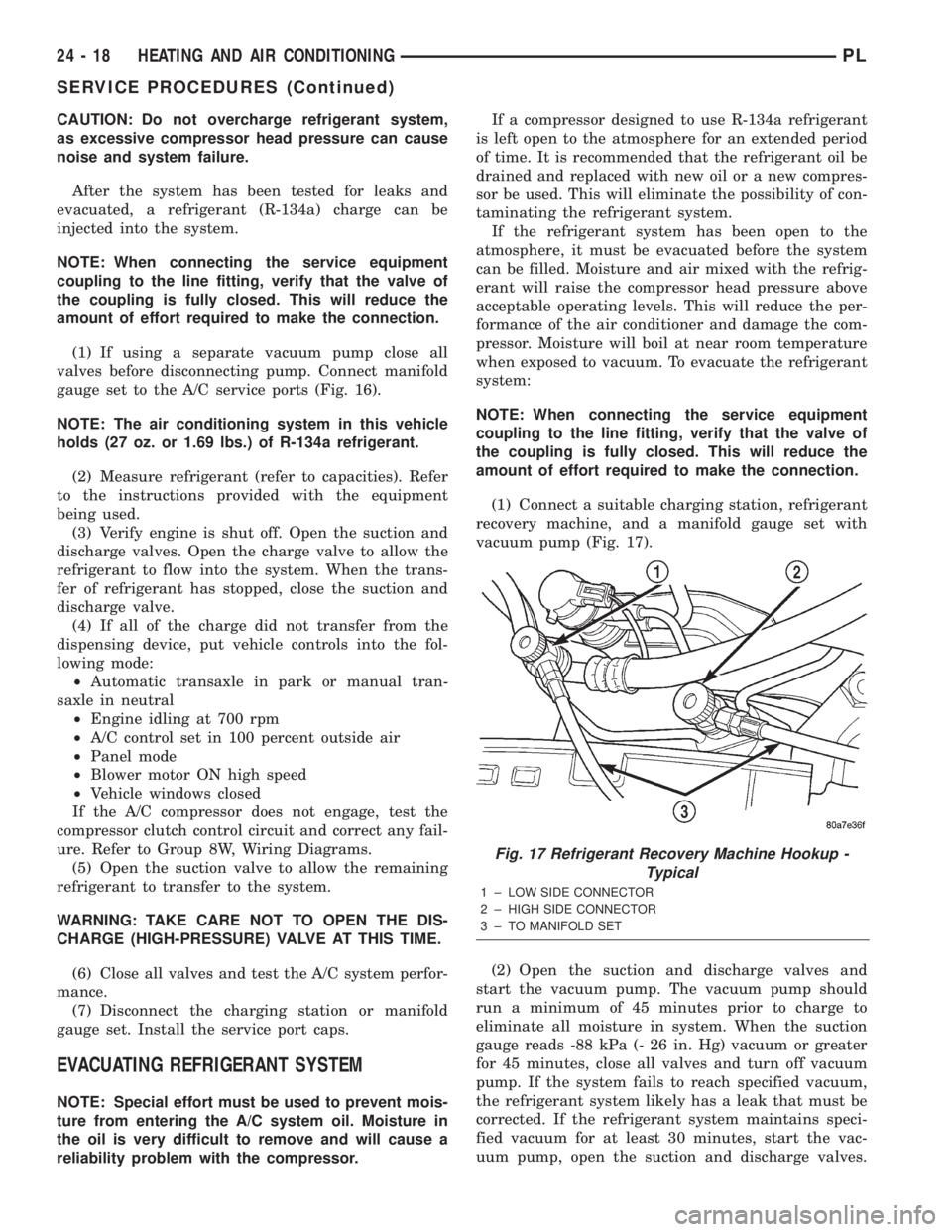
(1) Connect a suitable charging station, refrigerant
recovery machine, and a manifold gauge set with
vacuum pump (Fig. 17).
(2) Open the suction and discharge valves and
start the vacuum pump. The vacuum pump should
run a minimum of 45 minutes prior to charge to
eliminate all moisture in system. When the suction
gauge reads -88 kPa (- 26 in. Hg) vacuum or greater
for 45 minutes, close all valves and turn off vacuum
pump. If the system fails to reach specified vacuum,
the refrigerant system likely has a leak that must be
corrected. If the refrigerant system maintains speci-
fied vacuum for at least 30 minutes, start the vac-
uum pump, open the suction and discharge valves.
Fig. 17 Refrigerant Recovery Machine Hookup -
Typical
1 ± LOW SIDE CONNECTOR
2 ± HIGH SIDE CONNECTOR
3 ± TO MANIFOLD SET
24 - 18 HEATING AND AIR CONDITIONINGPL
SERVICE PROCEDURES (Continued)
Page 1251 of 1285
(1) Discharge refrigerant system using recovery/re-
cycling equipment if charge is present.
(2) Disconnect refrigerant lines from A/C compres-
sor. Cap the open lines to prevent moisture from
entering system.
(3) Remove compressor from vehicle.
(4) From suction port on top of compressor, drain
lubricant from compressor.
(5) Add system capacity minus the capacity of
components that have not been replaced. Refer to the
Lubricant Capacity Chart. Add lubricant through the
suction port on compressor. This is not to exceed 180
ml (6.10 oz.) in total.
(6) Install compressor and connect refrigerant
lines. Then evacuate and charge refrigerant system.
SYSTEM LEAK CHECKING
WARNING: R-134a SERVICE EQUIPMENT OR VEHI-
CLE A/C SYSTEM SHOULD NOT BE PRESSURE
TESTED OR LEAK TESTED WITH COMPRESSED
AIR. MIXTURE OF AIR and R-134a CAN BE COM-
BUSTIBLE AT ELEVATED PRESSURES. THESE MIX-
TURES ARE POTENTIALLY DANGEROUS AND MAY
RESULT IN FIRE OR EXPLOSION CAUSING INJURY
OR PROPERTY DAMAGE.
AVOID BREATHING A/C REFRIGERANT AND
LUBRICANT VAPOR OR MIST. EXPOSURE MAY
IRRITATE EYES, NOSE AND THROAT. USE ONLY
APPROVED SERVICE EQUIPMENT MEETING SAE
REQUIREMENTS TO DISCHARGE R-134a SYSTEM.
IF ACCIDENTAL SYSTEM DISCHARGE OCCURS,
VENTILATE WORK AREA BEFORE RESUMING SER-
VICE.
If the A/C system is not cooling properly, determine
if the refrigerant system is fully charged with
R-134a. This is accomplished by performing a system
Charge Level-Check or Fill. If while performing this
test A/C liquid line pressure is less than 345 kPa (50
psi) proceed to Empty Refrigerant System Leak Test.
If liquid line pressure is greater than 345 kPa (50
psi) proceed to low refrigerant level leak test. If the
refrigerant system is empty or low in refrigerant
charge, a leak at any line fitting or component seal is
likely. A review of the fittings, lines and components
for oily residue is an indication of the leak location.
To detect a leak in the refrigerant system, perform
one of the following procedures as indicated by the
symptoms.
EMPTY REFRIGERANT SYSTEM LEAK TEST
(1) Evacuate the refrigerant system to the lowest
degree of vacuum possible (approx. 28 in Hg.). Deter-
mine if the system holds a vacuum for 15 minutes. If
vacuum is held, a leak is probably not present. If sys-tem will not maintain vacuum level, proceed with
this procedure.
(2) Prepare a.284 Kg. (10 oz.) refrigerant charge to
be injected into the system.
(3) Connect and dispense.284 Kg. (10 oz.) of refrig-
erant into the evacuated refrigerant system.
(4) Proceed to Step 2 of Low Refrigerant Level
Leak Test.
LOW REFRIGERANT LEVEL LEAK TEST
(1) Determine if there is any (R-134a) refrigerant
in the system.
(2) Position the vehicle in a wind free work area.
This will aid in detecting small leaks.
(3) Bring the refrigerant system up to operating
temperature and pressure. This is done by allowing
the engine to run for five minutes with the system
set to the following:
²Transaxle in Park
²Engine Idling at 700 rpm
²A/C Controls Set in 100 percent outside air
²Blower switch in the high A/C position
²A/C in the ON position
²Open all windows
CAUTION: A leak detector designed for R-12 refrig-
erant (only) will not detect leaks in a R-134a refrig-
erant system.
(4) Shut off the vehicle and wait 2 to 7 minutes.
Then use an Electronic Leak Detector that is
designed to detect R-134a type refrigerant and search
for leaks. Fittings, lines, or components that appear
to be oily usually indicates a refrigerant leak. To
inspect the evaporator core for leaks, insert the leak
detector probe into the drain tube opening or a heat
duct. A R-134a dye is available to aid in leak detec-
tion, use only Chrysler approved refrigerant dye.
If a thorough leak check has been completed with-
out indication of a leak, proceed to System Charge
Level.
REMOVAL AND INSTALLATION
A/C FILTER/DRIER
The filter/drier is mounted in a rubber grommet on
the right side of the engine compartment. The refrig-
erant must be recovered from the A/C system before
replacing the filter/drier assembly.
WARNING: THE REFRIGERATION SYSTEM MUST
BE COMPLETELY RECOVERED BEFORE PRO-
CEEDING WITH THIS OPERATION.
24 - 20 HEATING AND AIR CONDITIONINGPL
SERVICE PROCEDURES (Continued)