Transmission and transfer case DODGE RAM 1500 1998 2.G User Guide
[x] Cancel search | Manufacturer: DODGE, Model Year: 1998, Model line: RAM 1500, Model: DODGE RAM 1500 1998 2.GPages: 2627
Page 85 of 2627

This measurement will give you the transmis-
sion yoke Output Angle (A).
(6) Rotate propeller shaft 90 degrees and place
Inclinometer on yoke bearing parallel to the shaft
(Fig. 5). Center bubble in sight glass and record mea-
surement. This measurement can also be taken at
the rear end of the shaft.
This measurement will give you the Propeller
Shaft Angle (C).(7) Rotate propeller shaft 90 degrees and place
inclinometer on companion flange yoke bearing par-
allel to the shaft (Fig. 6). Center bubble in sight glass
and record measurement.
This measurement will give you the pinion
Companion Flange Input Angle (B).
(8) Subtract smaller figure from larger (C minus
A) to obtain Transmission/Transfer CaseOutput
Operating Angle.
(9) Subtract smaller figure from larger (C minus
B) to obtain axleInput Operating Angle.
Refer to rules and example in (Fig. 7) for addi-
tional information.
RULES
²Good cancellation of U-joint operating angles
should be within 1 degree.
²Operating angles should be less than 3 degrees.
²Operating angles less than 10 degrees for double
cardan U-joint.
²At least 1/2 of one degree continuous operating
propeller shaft angle.
TWO-PIECE PROPELLER SHAFT
Two-piece propeller shaft angles measurement (Fig.
8) is the same as a one-piece propeller shaft.
Fig. 4 OUTPUT ANGLE (A)
Fig. 5 PROPELLER SHAFT ANGLE (C)
Fig. 6 INPUT ANGLE (B)
3 - 4 PROPELLER SHAFTDR
PROPELLER SHAFT (Continued)
Page 89 of 2627

REAR PROPELLER SHAFT
REMOVAL
(1) With vehicle in neutral, position vehicle on
hoist.
(2) Mark pinion flange or yoke and propeller shaft
flange or yoke (Fig. 12) for installation reference.
(3) Mark the outline of the center bearing (Fig. 13)
on the crossmember for installation reference, if
equipped.
(4) Remove center bearing mounting nuts, if
equipped.
(5) Remove pinion flange or yoke clamp bolts.
(6) Slide propeller shaft off transmission or trans-
fer case and remove shaft.
INSTALLATION
(1) Slide slip yoke onto the transmission/transfer
case output shaft.
(2) Align and install center bearing on crossmem-
ber, if equipped and tighten nuts to 54 N´m (40 ft.
lbs.).
(3) Align reference marks on propeller shaft and
pinion flange or pinon yoke.(4) Installnewbolts and tighten to:
²(Fig. 14) Companion flange bolts 15 N´m (85 ft.
lbs.)
²(Fig. 15) Yoke clamp bolts 29 N´m (22 ft. lbs.)
NOTE: Companion flange bolts incorporate a Loc-
titeTpatch, new bolts should be used. If bolts are
not available, clean bolts and apply LoctiteT242 to
the threads.
Fig. 12 COMPANION FLANGE
1 - PROPELLER SHAFT
2 - COMPANION FLANGE
3 - REFERENCE MARK
4 - SHAFT FLANGE YOKE
Fig. 13 CENTER BEARING
1 - CENTER BEARING
2 - DUST BOOT
3 - MOUNTING NUTS
Fig. 14 REAR PROPELLER SHAFT
1 - COMPANION FLANGE
2 - PROPELLER SHAFT
3 - 8 PROPELLER SHAFTDR
Page 109 of 2627
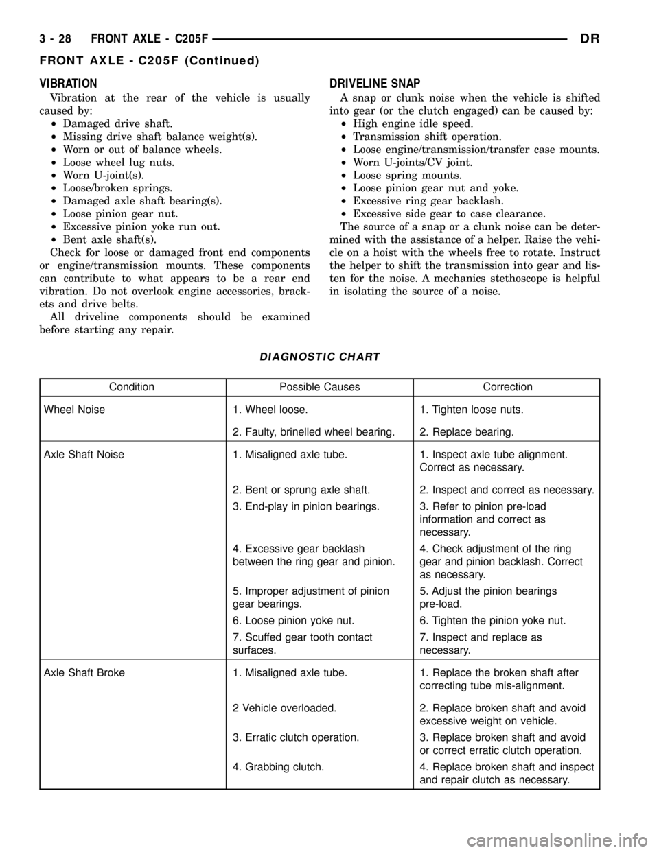
VIBRATION
Vibration at the rear of the vehicle is usually
caused by:
²Damaged drive shaft.
²Missing drive shaft balance weight(s).
²Worn or out of balance wheels.
²Loose wheel lug nuts.
²Worn U-joint(s).
²Loose/broken springs.
²Damaged axle shaft bearing(s).
²Loose pinion gear nut.
²Excessive pinion yoke run out.
²Bent axle shaft(s).
Check for loose or damaged front end components
or engine/transmission mounts. These components
can contribute to what appears to be a rear end
vibration. Do not overlook engine accessories, brack-
ets and drive belts.
All driveline components should be examined
before starting any repair.
DRIVELINE SNAP
A snap or clunk noise when the vehicle is shifted
into gear (or the clutch engaged) can be caused by:
²High engine idle speed.
²Transmission shift operation.
²Loose engine/transmission/transfer case mounts.
²Worn U-joints/CV joint.
²Loose spring mounts.
²Loose pinion gear nut and yoke.
²Excessive ring gear backlash.
²Excessive side gear to case clearance.
The source of a snap or a clunk noise can be deter-
mined with the assistance of a helper. Raise the vehi-
cle on a hoist with the wheels free to rotate. Instruct
the helper to shift the transmission into gear and lis-
ten for the noise. A mechanics stethoscope is helpful
in isolating the source of a noise.
DIAGNOSTIC CHART
Condition Possible Causes Correction
Wheel Noise 1. Wheel loose. 1. Tighten loose nuts.
2. Faulty, brinelled wheel bearing. 2. Replace bearing.
Axle Shaft Noise 1. Misaligned axle tube. 1. Inspect axle tube alignment.
Correct as necessary.
2. Bent or sprung axle shaft. 2. Inspect and correct as necessary.
3. End-play in pinion bearings. 3. Refer to pinion pre-load
information and correct as
necessary.
4. Excessive gear backlash
between the ring gear and pinion.4. Check adjustment of the ring
gear and pinion backlash. Correct
as necessary.
5. Improper adjustment of pinion
gear bearings.5. Adjust the pinion bearings
pre-load.
6. Loose pinion yoke nut. 6. Tighten the pinion yoke nut.
7. Scuffed gear tooth contact
surfaces.7. Inspect and replace as
necessary.
Axle Shaft Broke 1. Misaligned axle tube. 1. Replace the broken shaft after
correcting tube mis-alignment.
2 Vehicle overloaded. 2. Replace broken shaft and avoid
excessive weight on vehicle.
3. Erratic clutch operation. 3. Replace broken shaft and avoid
or correct erratic clutch operation.
4. Grabbing clutch. 4. Replace broken shaft and inspect
and repair clutch as necessary.
3 - 28 FRONT AXLE - C205FDR
FRONT AXLE - C205F (Continued)
Page 136 of 2627
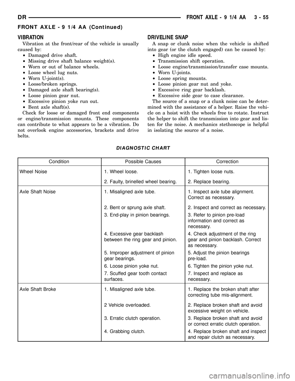
VIBRATION
Vibration at the front/rear of the vehicle is usually
caused by:
²Damaged drive shaft.
²Missing drive shaft balance weight(s).
²Worn or out of balance wheels.
²Loose wheel lug nuts.
²Worn U-joint(s).
²Loose/broken springs.
²Damaged axle shaft bearing(s).
²Loose pinion gear nut.
²Excessive pinion yoke run out.
²Bent axle shaft(s).
Check for loose or damaged front end components
or engine/transmission mounts. These components
can contribute to what appears to be a vibration. Do
not overlook engine accessories, brackets and drive
belts.
DRIVELINE SNAP
A snap or clunk noise when the vehicle is shifted
into gear (or the clutch engaged) can be caused by:
²High engine idle speed.
²Transmission shift operation.
²Loose engine/transmission/transfer case mounts.
²Worn U-joints.
²Loose spring mounts.
²Loose pinion gear nut and yoke.
²Excessive ring gear backlash.
²Excessive side gear to case clearance.
The source of a snap or a clunk noise can be deter-
mined with the assistance of a helper. Raise the vehi-
cle on a hoist with the wheels free to rotate. Instruct
the helper to shift the transmission into gear and lis-
ten for the noise. A mechanics stethoscope is helpful
in isolating the source of a noise.
DIAGNOSTIC CHART
Condition Possible Causes Correction
Wheel Noise 1. Wheel loose. 1. Tighten loose nuts.
2. Faulty, brinelled wheel bearing. 2. Replace bearing.
Axle Shaft Noise 1. Misaligned axle tube. 1. Inspect axle tube alignment.
Correct as necessary.
2. Bent or sprung axle shaft. 2. Inspect and correct as necessary.
3. End-play in pinion bearings. 3. Refer to pinion pre-load
information and correct as
necessary.
4. Excessive gear backlash
between the ring gear and pinion.4. Check adjustment of the ring
gear and pinion backlash. Correct
as necessary.
5. Improper adjustment of pinion
gear bearings.5. Adjust the pinion bearings
pre-load.
6. Loose pinion yoke nut. 6. Tighten the pinion yoke nut.
7. Scuffed gear tooth contact
surfaces.7. Inspect and replace as
necessary.
Axle Shaft Broke 1. Misaligned axle tube. 1. Replace the broken shaft after
correcting tube mis-alignment.
2 Vehicle overloaded. 2. Replace broken shaft and avoid
excessive weight on vehicle.
3. Erratic clutch operation. 3. Replace broken shaft and avoid
or correct erratic clutch operation.
4. Grabbing clutch. 4. Replace broken shaft and inspect
and repair clutch as necessary.
DRFRONT AXLE - 9 1/4 AA 3 - 55
FRONT AXLE - 9 1/4 AA (Continued)
Page 162 of 2627
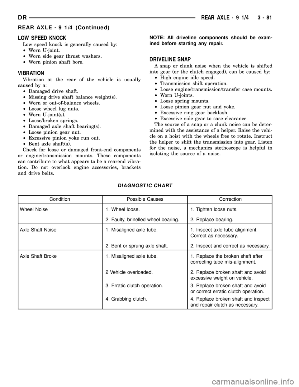
LOW SPEED KNOCK
Low speed knock is generally caused by:
²Worn U-joint.
²Worn side gear thrust washers.
²Worn pinion shaft bore.
VIBRATION
Vibration at the rear of the vehicle is usually
caused by a:
²Damaged drive shaft.
²Missing drive shaft balance weight(s).
²Worn or out-of-balance wheels.
²Loose wheel lug nuts.
²Worn U-joint(s).
²Loose/broken springs.
²Damaged axle shaft bearing(s).
²Loose pinion gear nut.
²Excessive pinion yoke run out.
²Bent axle shaft(s).
Check for loose or damaged front-end components
or engine/transmission mounts. These components
can contribute to what appears to be a rearend vibra-
tion. Do not overlook engine accessories, brackets
and drive belts.NOTE: All driveline components should be exam-
ined before starting any repair.
DRIVELINE SNAP
A snap or clunk noise when the vehicle is shifted
into gear (or the clutch engaged), can be caused by:
²High engine idle speed.
²Transmission shift operation.
²Loose engine/transmission/transfer case mounts.
²Worn U-joints.
²Loose spring mounts.
²Loose pinion gear nut and yoke.
²Excessive ring gear backlash.
²Excessive side gear to case clearance.
The source of a snap or a clunk noise can be deter-
mined with the assistance of a helper. Raise the vehi-
cle on a hoist with the wheels free to rotate. Instruct
the helper to shift the transmission into gear. Listen
for the noise, a mechanics stethoscope is helpful in
isolating the source of a noise.
DIAGNOSTIC CHART
Condition Possible Causes Correction
Wheel Noise 1. Wheel loose. 1. Tighten loose nuts.
2. Faulty, brinelled wheel bearing. 2. Replace bearing.
Axle Shaft Noise 1. Misaligned axle tube. 1. Inspect axle tube alignment.
Correct as necessary.
2. Bent or sprung axle shaft. 2. Inspect and correct as necessary.
Axle Shaft Broke 1. Misaligned axle tube. 1. Replace the broken shaft after
correcting tube mis-alignment.
2 Vehicle overloaded. 2. Replace broken shaft and avoid
excessive weight on vehicle.
3. Erratic clutch operation. 3. Replace broken shaft and avoid
or correct erratic clutch operation.
4. Grabbing clutch. 4. Replace broken shaft and inspect
and repair clutch as necessary.
DRREAR AXLE - 9 1/4 3 - 81
REAR AXLE - 9 1/4 (Continued)
Page 194 of 2627
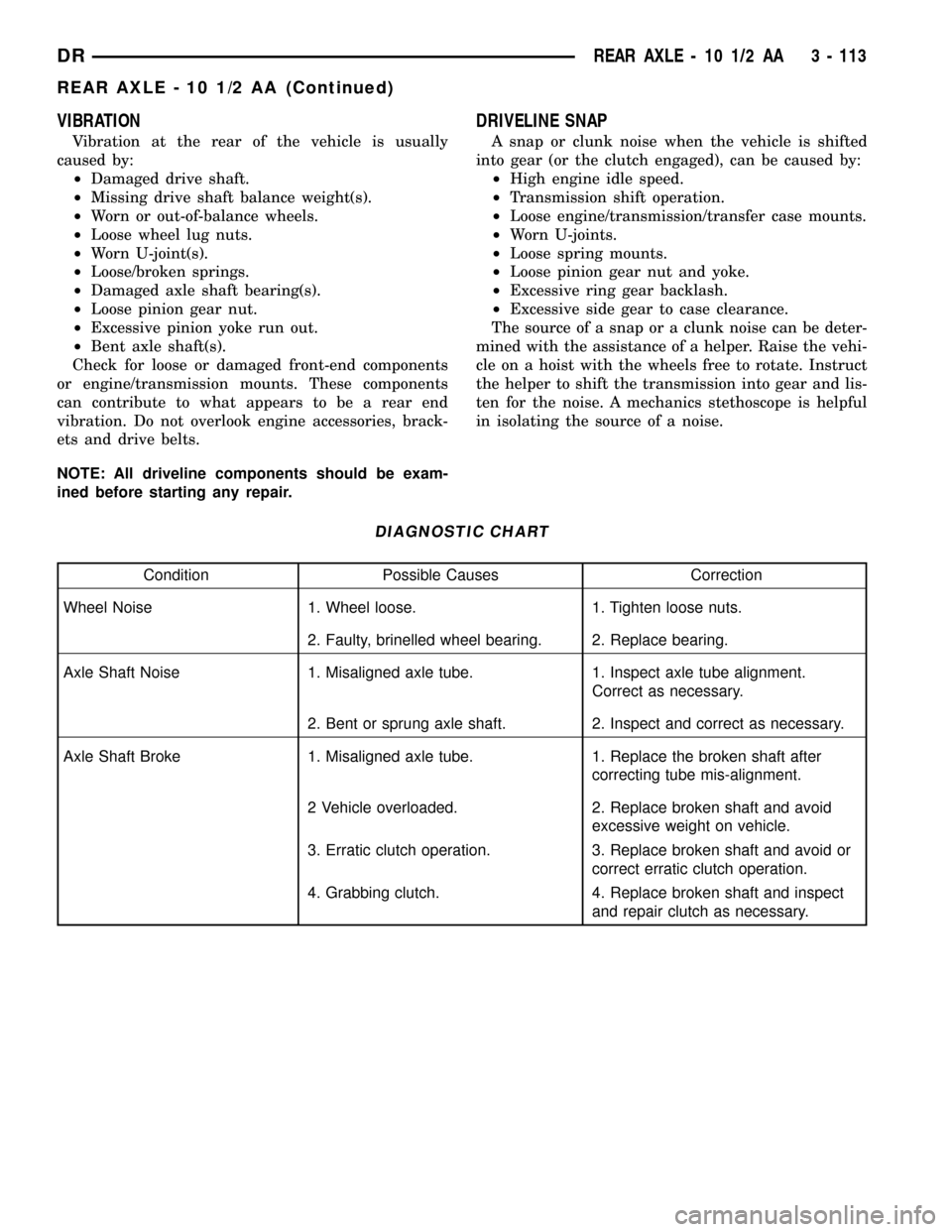
VIBRATION
Vibration at the rear of the vehicle is usually
caused by:
²Damaged drive shaft.
²Missing drive shaft balance weight(s).
²Worn or out-of-balance wheels.
²Loose wheel lug nuts.
²Worn U-joint(s).
²Loose/broken springs.
²Damaged axle shaft bearing(s).
²Loose pinion gear nut.
²Excessive pinion yoke run out.
²Bent axle shaft(s).
Check for loose or damaged front-end components
or engine/transmission mounts. These components
can contribute to what appears to be a rear end
vibration. Do not overlook engine accessories, brack-
ets and drive belts.
NOTE: All driveline components should be exam-
ined before starting any repair.
DRIVELINE SNAP
A snap or clunk noise when the vehicle is shifted
into gear (or the clutch engaged), can be caused by:
²High engine idle speed.
²Transmission shift operation.
²Loose engine/transmission/transfer case mounts.
²Worn U-joints.
²Loose spring mounts.
²Loose pinion gear nut and yoke.
²Excessive ring gear backlash.
²Excessive side gear to case clearance.
The source of a snap or a clunk noise can be deter-
mined with the assistance of a helper. Raise the vehi-
cle on a hoist with the wheels free to rotate. Instruct
the helper to shift the transmission into gear and lis-
ten for the noise. A mechanics stethoscope is helpful
in isolating the source of a noise.
DIAGNOSTIC CHART
Condition Possible Causes Correction
Wheel Noise 1. Wheel loose. 1. Tighten loose nuts.
2. Faulty, brinelled wheel bearing. 2. Replace bearing.
Axle Shaft Noise 1. Misaligned axle tube. 1. Inspect axle tube alignment.
Correct as necessary.
2. Bent or sprung axle shaft. 2. Inspect and correct as necessary.
Axle Shaft Broke 1. Misaligned axle tube. 1. Replace the broken shaft after
correcting tube mis-alignment.
2 Vehicle overloaded. 2. Replace broken shaft and avoid
excessive weight on vehicle.
3. Erratic clutch operation. 3. Replace broken shaft and avoid or
correct erratic clutch operation.
4. Grabbing clutch. 4. Replace broken shaft and inspect
and repair clutch as necessary.
DRREAR AXLE - 10 1/2 AA 3 - 113
REAR AXLE - 10 1/2 AA (Continued)
Page 222 of 2627
VIBRATION
Vibration at the rear of the vehicle is usually
caused by:
²Damaged drive shaft.
²Missing drive shaft balance weight(s).
²Worn or out-of-balance wheels.
²Loose wheel lug nuts.
²Worn U-joint(s).
²Loose/broken springs.
²Damaged axle shaft bearing(s).
²Loose pinion gear nut.
²Excessive pinion yoke run out.
²Bent axle shaft(s).
Check for loose or damaged front-end components
or engine/transmission mounts. These components
can contribute to what appears to be a rear end
vibration. Do not overlook engine accessories, brack-
ets and drive belts.
NOTE: All driveline components should be exam-
ined before starting any repair.
DRIVELINE SNAP
A snap or clunk noise when the vehicle is shifted
into gear (or the clutch engaged), can be caused by:
²High engine idle speed.
²Transmission shift operation.
²Loose engine/transmission/transfer case mounts.
²Worn U-joints.
²Loose spring mounts.
²Loose pinion gear nut and yoke.
²Excessive ring gear backlash.
²Excessive side gear to case clearance.
The source of a snap or a clunk noise can be deter-
mined with the assistance of a helper. Raise the vehi-
cle on a hoist with the wheels free to rotate. Instruct
the helper to shift the transmission into gear and lis-
ten for the noise. A mechanics stethoscope is helpful
in isolating the source of a noise.
DIAGNOSTIC CHART
Condition Possible Causes Correction
Wheel Noise 1. Wheel loose. 1. Tighten loose nuts.
2. Faulty, brinelled wheel bearing. 2. Replace bearing.
Axle Shaft Noise 1. Misaligned axle tube. 1. Inspect axle tube alignment.
Correct as necessary.
2. Bent or sprung axle shaft. 2. Inspect and correct as necessary.
Axle Shaft Broke 1. Misaligned axle tube. 1. Replace the broken shaft after
correcting tube mis-alignment.
2 Vehicle overloaded. 2. Replace broken shaft and avoid
excessive weight on vehicle.
3. Erratic clutch operation. 3. Replace broken shaft and avoid or
correct erratic clutch operation.
4. Grabbing clutch. 4. Replace broken shaft and inspect
and repair clutch as necessary.
DRREAR AXLE - 11 1/2 AA 3 - 141
REAR AXLE - 11 1/2 AA (Continued)
Page 306 of 2627
CONDITION POSSIBLE CAUSES CORRECTION
Partial engagement of clutch disc.
One side of disc is worn and the
other side is glazed and lightly
worn.1. Clutch pressure plate position
incorrect.1. Replace clutch disc and cover.
2. Clutch cover, spring, or release
fingers bent or distorted.2. Replace clutch disc and cover.
3. Clutch disc damaged or
distorted.2. Replace clutch disc.
4. Clutch misalignment. 4. Check alignment and runout of
flywheel, disc, pressure plate, andùr
clutch housing. Correct as
necessary.
SPECIFICATIONS
TORQUE SPECIFICATIONS
DESCRIPTION N´m Ft. Lbs. In. Lbs.
Slave Cylinder Nuts 23 17 -
Clutch Master Cylinder
Nuts28 21 -
Pressure Plate Bolts - V6
&V850 37 -
Pressure Plate Bolts - V10 30 22.5 -
Pressure Plate Bolts -
Diesel30 22.5 -
Release Bearing Pivot 23 17 -
Flywheel Bolts 95 70 -
CLUTCH DISC
REMOVAL
(1) Support engine with wood block and adjustable
jack stand, to prevent strain on engine mounts.
(2) Remove transmission and transfer case, if
equipped.
(3) If pressure plate will be reused, mark the posi-
tion on flywheel with paint or scriber (Fig. 1). Also
note location marks on the pressure next to the bolt
holes. The mark will be a L or a circle with an X in
it.
(4) Insert clutch alignment tool through clutch disc
and into pilot bushing, to hold disc in place while
removing bolts.
(5) Loosen pressure plate bolts evenly, a few
threads at a time and in a diagonal pattern to pre-
vent warping the plate.
(6) Remove bolts completely and remove pressure
plate, disc and alignment tool.
INSTALLATION
(1) Check runout and free operation of new clutch
disc.
(2) Lubricate crankshaft pilot bearing with a NLGI
- 2 rated grease.
(3) Install clutch alignment tool in clutch disc hub
with the raised side of hub is facing away from the
flywheel.
NOTE: Flywheel side is imprinted on the disc face.
(4) Install alignment tool in pilot bearing and posi-
tion disc on the flywheel.
(5) Position pressure plate over disc and onto the
flywheel (Fig. 2).
(6) Align and hold pressure plate in position and
install bolts finger tight.
(7) Tighten bolts evenly and a few threads at a
time in a diagonal pattern.
CAUTION: Bolts must be tightened evenly and to
specified torque to avoid warping pressure plate
cover.
DRCLUTCH 6 - 5
CLUTCH (Continued)
Page 308 of 2627

(11) Wipe pilot bearing surface clean.
(12) Install release lever and bearing in clutch
housing. Verify spring clips that retain fork on pivot
ball and release bearing on fork are installed prop-
erly (Fig. 5).
NOTE: If release lever is installed correctly, the
lever part number will be toward the bottom of the
transmission and right side up. There is also a
stamped ªIº in the lever which goes to the pivot ball
side of the transmission.
(13) Install transmission and transfer case if
equipped.
(14) Check fluid level in clutch master cylinder.
CLUTCH HOUSING
DIAGNOSIS AND TESTING
The clutch housing maintains alignment between
the crankshaft and transmission input shaft. Mis-
alignment can cause clutch noise, hard shifting,
incomplete release and chatter. Also premature pilot
bearing, cover release fingers and clutch disc wear.
In severe cases, it can cause premature wear of the
transmission input shaft and front bearing.
NOTE: Only the NV4500 clutch housing can be
checked using the following bore and face runout
procedures. The NV5600 clutch housing is a inte-
gral part of the transmission and can only be
checked off the vehicle.
CLUTCH HOUSING BORE RUNOUT
CAUTION: On diesel engines if housing bore runout
exceeds 0.015 inch, the clutch housing/transmis-
sion adapter plate must be replaced. On gas
engines if housing bore runout exceeds 0.053 in.
the clutch housing must be replaced.
NOTE: Offset dowels are available for gas engines
to correct housing bore runout. They are not avail-
able for diesel engines.
(1) Remove the clutch housing.
(2) Remove the clutch cover and disc.
(3) Replace one of the flywheel bolts with an
appropriate size threaded rod that is 10 in. (25.4 cm)
long (Fig. 6). The rod will be used to mount the dial
indicator.
(4) Remove release fork from the clutch housing.
(5) Install clutch housing. Tighten the housing
bolts nearest the alignment dowels first.
(6) Mount dial indicator on the threaded rod and
position indicator plunger on the clutch housing bore
(Fig. 7).
(7) Rotate crankshaft until indicator plunger is at
the topof the housing bore. Zero the indicator at this
point.
(8) Rotate crankshaft and record indicator read-
ings at eight points (45É apart) around the bore (Fig.
8). Take measurement at least twice for accuracy.
(9) Subtract each reading from the one 180É oppo-
site to determine runout and direction. Bore runout
example (Fig. 8):
²0.000 ± (±0.007) = 0.007 in.
²+0.002 ± (±0.010) = 0.012 in.
²+0.004 ± (±0.005) = 0.009 in.
²±0.001 ± (+0.001) = ±0.002 in.
Fig. 5 FORK, BEARING AND SPRING CLIPS
1 - FORK
2 - SPRING CLIP
3 - BEARING
4 - SPRING CLIP
Fig. 6 DIAL INDICATOR MOUNTING STUD
1 - 7/16 - 20 THREAD
2 - NUT
3 - STUD OR THREADED ROD
4 - 10 INCHES LONG
DRCLUTCH 6 - 7
CLUTCH DISC (Continued)
Page 310 of 2627

To correct this example (Fig. 11) the shims needed
between the clutch housing and transmission are:
²0.009 in. at the 0.000 corner
²0.012 in. at the ±0.003 corner
²0.013 in. at the ±0.004 corner
After installing the clutch assembly and housing,
tighten the housing bolts nearest the alignment dow-
els first.
NOTE: Shims can be made from shim stock or sim-
ilar materials of the required thickness (Fig. 12).
REMOVAL
(1) Remove transmission and transfer case (Fig.
13).
(2) Remove starter from clutch housing.
(3) Remove structural dust cover bolts from clutch
housing.
CAUTION: Do not remove structural dust cover
from enigne block. If cover is removed clutch hous-
ing and cover must be aligned with the engine.(4) Remove clutch housing bolts and remove hous-
ing from the engine.
INSTALLATION
(1) Clean housing mounting surface of engine
block with wax and grease remover.
(2) Verify that clutch housing alignment dowels
are in good condition and properly seated.
(3) Transfer slave cylinder, release fork and boot,
fork pivot stud and wire/hose brackets to new hous-
ing.
(4) Install structural dust cover if removed (Refer
to 9 - ENGINE/ENGINE BLOCK/STRUCTURAL
COVER - INSTALLATION).
(5) Align and install clutch housing on engine (Fig.
14). Tighten housing bolts across the top of the hous-
ing first and to the following torque values:
²ªAº bolts 1/4in. diameter - 4.5 N´m (40 in.lb.)
²ªAº bolts 3/8in. diameter - 40 N´m (30 ft.lb.)
²ªAº bolts 7/16in. diameter - 68 N´m (50 ft.lb.)
²ªBº bolts for 5.7L 5.9L TD/8.0L engines - 47.5
N´m (40 ft.lb.)
²ªCº bolts for 5.7L engine - 68 N´m (50 ft.lb.)
²ªCº bolts for 5.9L TD engine - 47.5 N´m (35
ft.lb.)
²ªCº bolts for 8.0L engine - 74.5 N´m (55 ft.lb.)
(6) Install starter to clutch housing.
(7) Install transmission and transfer case, if
equipped.
CLUTCH RELEASE BEARING
REMOVAL
(1) Remove transmission and transfer case, if
equipped.
(2) Remove spring clip.
Fig. 11 MEASUREMENT POINTS AND READINGS
1 - CLUTCH HOUSING FACE CIRCLE (AT RIM OF BORE)
Fig. 12 ALIGNMENT SHIMS
1 - CUT/DRILL BOLT HOLE TO SIZE
2 - SHIM STOCK
3 - MAKE SHIM 1-INCH DIAMETER
Fig. 13 TRANSMISSION/CLUTCH HOUSING-NV4500
1 - CLUTCH HOUSING
2 - TRANSMISSION
DRCLUTCH 6 - 9
CLUTCH HOUSING (Continued)