One DODGE RAM 1500 1998 2.G Service Manual
[x] Cancel search | Manufacturer: DODGE, Model Year: 1998, Model line: RAM 1500, Model: DODGE RAM 1500 1998 2.GPages: 2627
Page 118 of 2627
(23) Subtract 0.05 mm (0.002 in.) from the dial
indicator reading to compensate for backlash between
ring and pinion gears. Add the resulting measure-
ment to the thickness of the single dummy shim.
This is the thickness of shim required to achieve
proper backlash.
(24) Subtract the backlash shim thickness from
the total preload shim thickness. The remainder is
the shim thickness required on the pinion side of the
housing.
(25) Rotate dial indicator out of the way on pilot
stud.
(26) Remove differential case, dummy bearings
and dummy shim from the housing.
(27) Install new side bearing cones and cups on
differential case.
(28) Install Spreader W-129-B and Adapter Plates
8142-A on the housing and spread open enough to
receive differential case.
CAUTION: Never spread over 0.50 mm (0.020 in). If
the housing is over-spread, it could be distorted or
damaged.
(29) Place the side bearing shims in the differen-
tial housing against the housing shoulder.
(30) Install the differential case in the housing.
(31) Rotate the differential case several times to
seat the side bearings.
(32) Position the dial indicator plunger against a
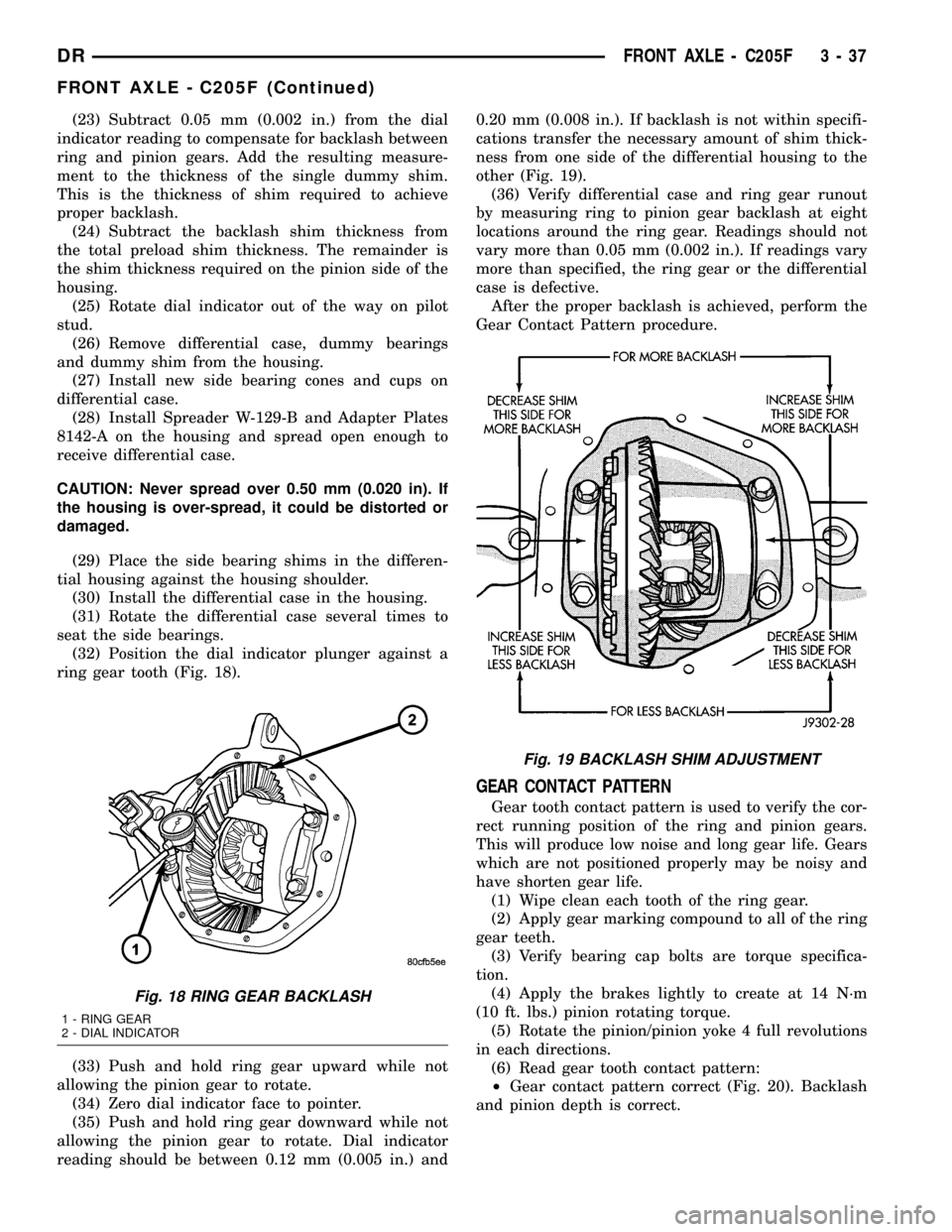
ring gear tooth (Fig. 18).
(33) Push and hold ring gear upward while not
allowing the pinion gear to rotate.
(34) Zero dial indicator face to pointer.
(35) Push and hold ring gear downward while not
allowing the pinion gear to rotate. Dial indicator
reading should be between 0.12 mm (0.005 in.) and0.20 mm (0.008 in.). If backlash is not within specifi-
cations transfer the necessary amount of shim thick-
ness from one side of the differential housing to the
other (Fig. 19).
(36) Verify differential case and ring gear runout
by measuring ring to pinion gear backlash at eight
locations around the ring gear. Readings should not
vary more than 0.05 mm (0.002 in.). If readings vary
more than specified, the ring gear or the differential
case is defective.
After the proper backlash is achieved, perform the
Gear Contact Pattern procedure.
GEAR CONTACT PATTERN
Gear tooth contact pattern is used to verify the cor-
rect running position of the ring and pinion gears.
This will produce low noise and long gear life. Gears
which are not positioned properly may be noisy and
have shorten gear life.
(1) Wipe clean each tooth of the ring gear.
(2) Apply gear marking compound to all of the ring
gear teeth.
(3) Verify bearing cap bolts are torque specifica-
tion.
(4) Apply the brakes lightly to create at 14 N´m
(10 ft. lbs.) pinion rotating torque.
(5) Rotate the pinion/pinion yoke 4 full revolutions
in each directions.
(6) Read gear tooth contact pattern:
²Gear contact pattern correct (Fig. 20). Backlash
and pinion depth is correct.
Fig. 18 RING GEAR BACKLASH
1 - RING GEAR
2 - DIAL INDICATOR
Fig. 19 BACKLASH SHIM ADJUSTMENT
DRFRONT AXLE - C205F 3 - 37
FRONT AXLE - C205F (Continued)
Page 128 of 2627
(12) Remove spreader from housing.
DISASSEMBLY
(1) Remove ring gear.
(2) Remove roll-pin holding mate shaft in housing.
(3) Remove pinion gear mate shaft.
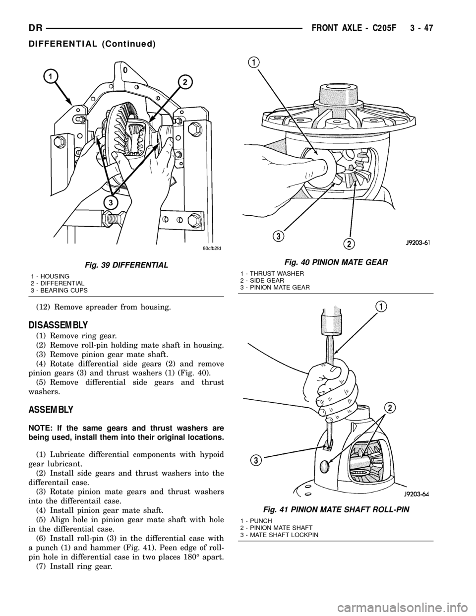
(4) Rotate differential side gears (2) and remove
pinion gears (3) and thrust washers (1) (Fig. 40).
(5) Remove differential side gears and thrust
washers.
ASSEMBLY
NOTE: If the same gears and thrust washers are
being used, install them into their original locations.
(1) Lubricate differential components with hypoid
gear lubricant.
(2) Install side gears and thrust washers into the
differentail case.
(3) Rotate pinion mate gears and thrust washers
into the differentail case.
(4) Install pinion gear mate shaft.
(5) Align hole in pinion gear mate shaft with hole
in the differential case.
(6) Install roll-pin (3) in the differential case with
a punch (1) and hammer (Fig. 41). Peen edge of roll-
pin hole in differential case in two places 180É apart.
(7) Install ring gear.
Fig. 39 DIFFERENTIAL
1 - HOUSING
2 - DIFFERENTIAL
3 - BEARING CUPS
Fig. 40 PINION MATE GEAR
1 - THRUST WASHER
2 - SIDE GEAR
3 - PINION MATE GEAR
Fig. 41 PINION MATE SHAFT ROLL-PIN
1 - PUNCH
2 - PINION MATE SHAFT
3 - MATE SHAFT LOCKPIN
DRFRONT AXLE - C205F 3 - 47
DIFFERENTIAL (Continued)
Page 130 of 2627
PINION GEAR/RING GEAR
REMOVAL
NOTE: The ring gear and pinion are serviced in a
matched set. Never replace one without replacing
the other.
(1) Remove differential from housing.
(2) Place differential case in a vise with soft jaw
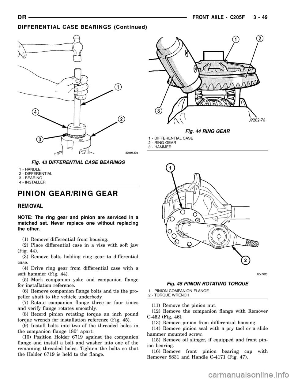
(Fig. 44).
(3) Remove bolts holding ring gear to differential
case.
(4) Drive ring gear from differential case with a
soft hammer (Fig. 44).
(5) Mark companion yoke and companion flange
for installation reference.
(6) Remove companion flange bolts and tie the pro-
peller shaft to the vehicle underbody.
(7) Rotate companion flange three or four times
and verify flange rotates smoothly.
(8) Record pinion rotating torque an inch pound
torque wrench for installation reference (Fig. 45).
(9) Install bolts into two of the threaded holes in
the companion flange 180É apart.
(10) Position Holder 6719 against the companion
flange and install a bolt and washer into one of the
remaining threaded holes. Tighten the bolts so that
the Holder 6719 is held to the flange.(11) Remove the pinion nut.
(12) Remove the companion flange with Remover
C-452 (Fig. 46).
(13) Remove pinion from differential housing.
(14) Remove pinion seal with a pry tool or a slide
hammer mounted screw.
(15) Remove oil slinger, if equipped and front pin-
ion bearing.
(16) Remove front pinion bearing cup with
Remover 8831 and Handle C-4171 (Fig. 47).
Fig. 43 DIFFERENTIAL CASE BEARINGS
1 - HANDLE
2 - DIFFERENTIAL
3 - BEARING
4 - INSTALLER
Fig. 44 RING GEAR
1 - DIFFERENTIAL CASE
2 - RING GEAR
3 - HAMMER
Fig. 45 PINION ROTATING TORQUE
1 - PINION COMPANION FLANGE
2 - TORQUE WRENCH
DRFRONT AXLE - C205F 3 - 49
DIFFERENTIAL CASE BEARINGS (Continued)
Page 132 of 2627
INSTALLATION
NOTE: The ring gear and pinion are serviced in a
matched set. Never replace one gear without replac-
ing the other matching gear. If ring and pinion
gears or bearings are replaced, Refer to Adjust-
ments for Pinion Gear Depth Setting.
(1) Apply Mopar Door Ease or equivalent lubricant
to outside surface of the bearing cups.
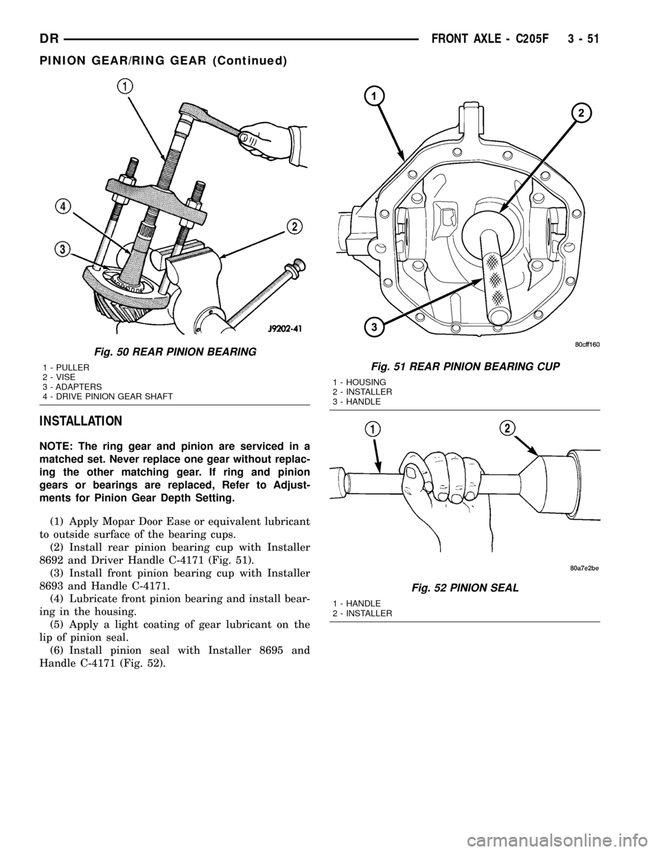
(2) Install rear pinion bearing cup with Installer
8692 and Driver Handle C-4171 (Fig. 51).
(3) Install front pinion bearing cup with Installer
8693 and Handle C-4171.
(4) Lubricate front pinion bearing and install bear-
ing in the housing.
(5) Apply a light coating of gear lubricant on the
lip of pinion seal.
(6) Install pinion seal with Installer 8695 and
Handle C-4171 (Fig. 52).
Fig. 50 REAR PINION BEARING
1 - PULLER
2 - VISE
3 - ADAPTERS
4 - DRIVE PINION GEAR SHAFTFig. 51 REAR PINION BEARING CUP
1 - HOUSING
2 - INSTALLER
3 - HANDLE
Fig. 52 PINION SEAL
1 - HANDLE
2 - INSTALLER
DRFRONT AXLE - C205F 3 - 51
PINION GEAR/RING GEAR (Continued)
Page 136 of 2627
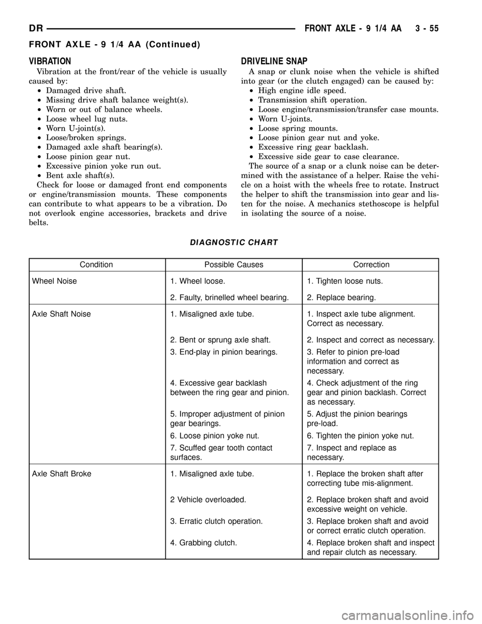
VIBRATION
Vibration at the front/rear of the vehicle is usually
caused by:
²Damaged drive shaft.
²Missing drive shaft balance weight(s).
²Worn or out of balance wheels.
²Loose wheel lug nuts.
²Worn U-joint(s).
²Loose/broken springs.
²Damaged axle shaft bearing(s).
²Loose pinion gear nut.
²Excessive pinion yoke run out.
²Bent axle shaft(s).
Check for loose or damaged front end components
or engine/transmission mounts. These components
can contribute to what appears to be a vibration. Do
not overlook engine accessories, brackets and drive
belts.
DRIVELINE SNAP
A snap or clunk noise when the vehicle is shifted
into gear (or the clutch engaged) can be caused by:
²High engine idle speed.
²Transmission shift operation.
²Loose engine/transmission/transfer case mounts.
²Worn U-joints.
²Loose spring mounts.
²Loose pinion gear nut and yoke.
²Excessive ring gear backlash.
²Excessive side gear to case clearance.
The source of a snap or a clunk noise can be deter-
mined with the assistance of a helper. Raise the vehi-
cle on a hoist with the wheels free to rotate. Instruct
the helper to shift the transmission into gear and lis-
ten for the noise. A mechanics stethoscope is helpful
in isolating the source of a noise.
DIAGNOSTIC CHART
Condition Possible Causes Correction
Wheel Noise 1. Wheel loose. 1. Tighten loose nuts.
2. Faulty, brinelled wheel bearing. 2. Replace bearing.
Axle Shaft Noise 1. Misaligned axle tube. 1. Inspect axle tube alignment.
Correct as necessary.
2. Bent or sprung axle shaft. 2. Inspect and correct as necessary.
3. End-play in pinion bearings. 3. Refer to pinion pre-load
information and correct as
necessary.
4. Excessive gear backlash
between the ring gear and pinion.4. Check adjustment of the ring
gear and pinion backlash. Correct
as necessary.
5. Improper adjustment of pinion
gear bearings.5. Adjust the pinion bearings
pre-load.
6. Loose pinion yoke nut. 6. Tighten the pinion yoke nut.
7. Scuffed gear tooth contact
surfaces.7. Inspect and replace as
necessary.
Axle Shaft Broke 1. Misaligned axle tube. 1. Replace the broken shaft after
correcting tube mis-alignment.
2 Vehicle overloaded. 2. Replace broken shaft and avoid
excessive weight on vehicle.
3. Erratic clutch operation. 3. Replace broken shaft and avoid
or correct erratic clutch operation.
4. Grabbing clutch. 4. Replace broken shaft and inspect
and repair clutch as necessary.
DRFRONT AXLE - 9 1/4 AA 3 - 55
FRONT AXLE - 9 1/4 AA (Continued)
Page 137 of 2627
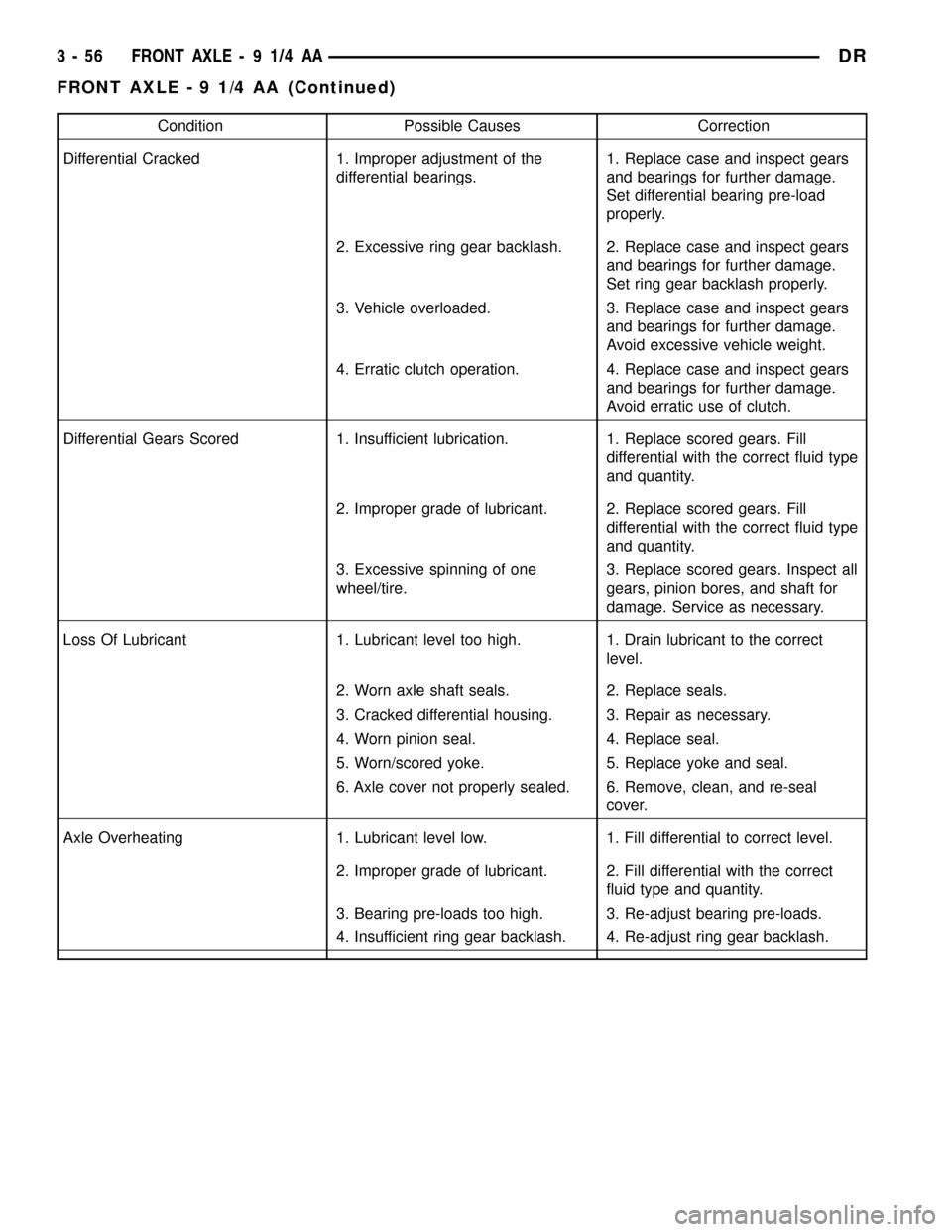
Condition Possible Causes Correction
Differential Cracked 1. Improper adjustment of the
differential bearings.1. Replace case and inspect gears
and bearings for further damage.
Set differential bearing pre-load
properly.
2. Excessive ring gear backlash. 2. Replace case and inspect gears
and bearings for further damage.
Set ring gear backlash properly.
3. Vehicle overloaded. 3. Replace case and inspect gears
and bearings for further damage.
Avoid excessive vehicle weight.
4. Erratic clutch operation. 4. Replace case and inspect gears
and bearings for further damage.
Avoid erratic use of clutch.
Differential Gears Scored 1. Insufficient lubrication. 1. Replace scored gears. Fill
differential with the correct fluid type
and quantity.
2. Improper grade of lubricant. 2. Replace scored gears. Fill
differential with the correct fluid type
and quantity.
3. Excessive spinning of one
wheel/tire.3. Replace scored gears. Inspect all
gears, pinion bores, and shaft for
damage. Service as necessary.
Loss Of Lubricant 1. Lubricant level too high. 1. Drain lubricant to the correct
level.
2. Worn axle shaft seals. 2. Replace seals.
3. Cracked differential housing. 3. Repair as necessary.
4. Worn pinion seal. 4. Replace seal.
5. Worn/scored yoke. 5. Replace yoke and seal.
6. Axle cover not properly sealed. 6. Remove, clean, and re-seal
cover.
Axle Overheating 1. Lubricant level low. 1. Fill differential to correct level.
2. Improper grade of lubricant. 2. Fill differential with the correct
fluid type and quantity.
3. Bearing pre-loads too high. 3. Re-adjust bearing pre-loads.
4. Insufficient ring gear backlash. 4. Re-adjust ring gear backlash.
3 - 56 FRONT AXLE - 9 1/4 AADR
FRONT AXLE - 9 1/4 AA (Continued)
Page 138 of 2627
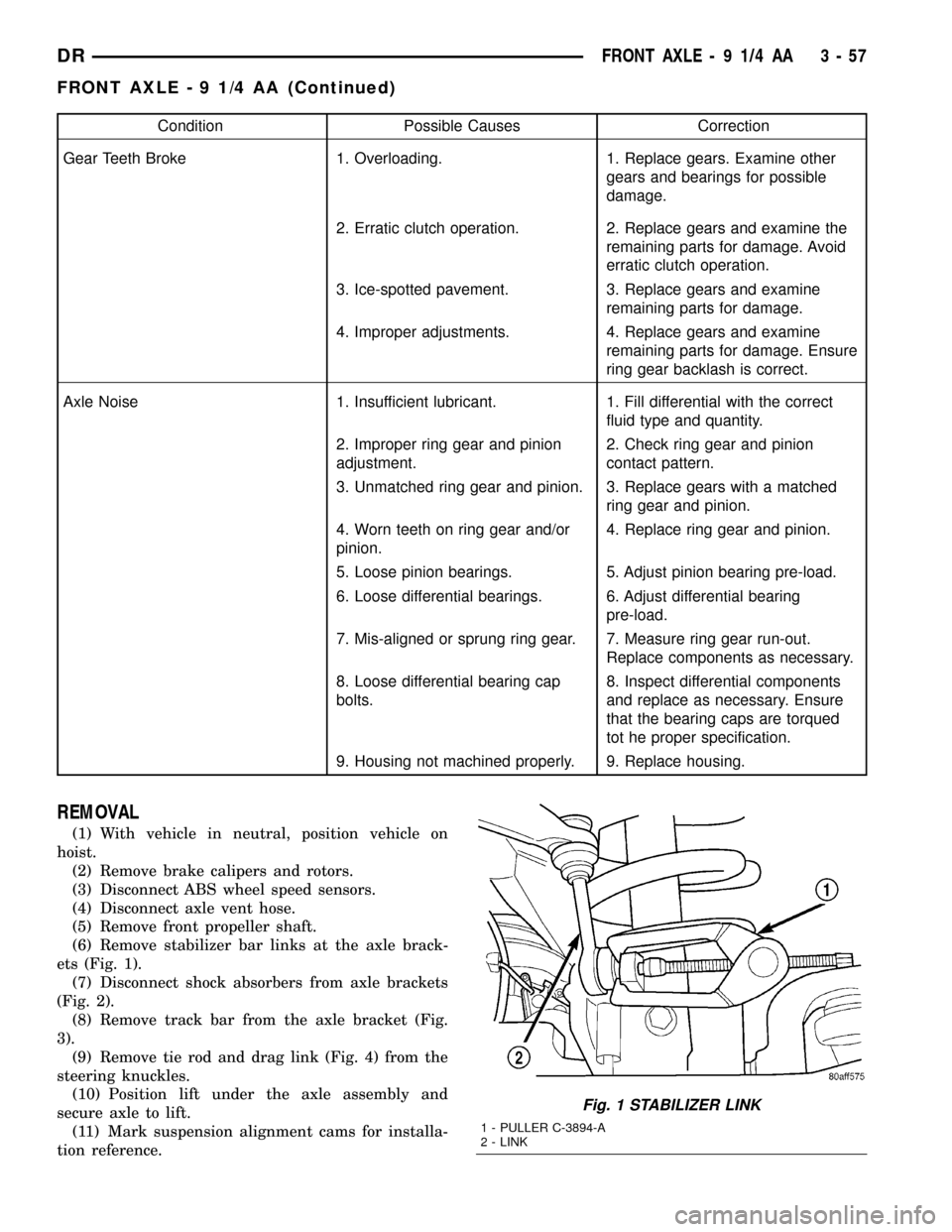
Condition Possible Causes Correction
Gear Teeth Broke 1. Overloading. 1. Replace gears. Examine other
gears and bearings for possible
damage.
2. Erratic clutch operation. 2. Replace gears and examine the
remaining parts for damage. Avoid
erratic clutch operation.
3. Ice-spotted pavement. 3. Replace gears and examine
remaining parts for damage.
4. Improper adjustments. 4. Replace gears and examine
remaining parts for damage. Ensure
ring gear backlash is correct.
Axle Noise 1. Insufficient lubricant. 1. Fill differential with the correct
fluid type and quantity.
2. Improper ring gear and pinion
adjustment.2. Check ring gear and pinion
contact pattern.
3. Unmatched ring gear and pinion. 3. Replace gears with a matched
ring gear and pinion.
4. Worn teeth on ring gear and/or
pinion.4. Replace ring gear and pinion.
5. Loose pinion bearings. 5. Adjust pinion bearing pre-load.
6. Loose differential bearings. 6. Adjust differential bearing
pre-load.
7. Mis-aligned or sprung ring gear. 7. Measure ring gear run-out.
Replace components as necessary.
8. Loose differential bearing cap
bolts.8. Inspect differential components
and replace as necessary. Ensure
that the bearing caps are torqued
tot he proper specification.
9. Housing not machined properly. 9. Replace housing.
REMOVAL
(1) With vehicle in neutral, position vehicle on
hoist.
(2) Remove brake calipers and rotors.
(3) Disconnect ABS wheel speed sensors.
(4) Disconnect axle vent hose.
(5) Remove front propeller shaft.
(6) Remove stabilizer bar links at the axle brack-
ets (Fig. 1).
(7) Disconnect shock absorbers from axle brackets
(Fig. 2).
(8) Remove track bar from the axle bracket (Fig.
3).
(9) Remove tie rod and drag link (Fig. 4) from the
steering knuckles.
(10) Position lift under the axle assembly and
secure axle to lift.
(11) Mark suspension alignment cams for installa-
tion reference.
Fig. 1 STABILIZER LINK
1 - PULLER C-3894-A
2 - LINK
DRFRONT AXLE - 9 1/4 AA 3 - 57
FRONT AXLE - 9 1/4 AA (Continued)
Page 139 of 2627
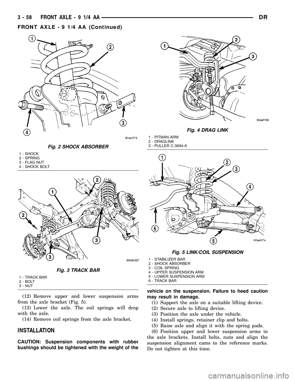
(12) Remove upper and lower suspension arms
from the axle bracket (Fig. 5).
(13) Lower the axle. The coil springs will drop
with the axle.
(14) Remove coil springs from the axle bracket.
INSTALLATION
CAUTION: Suspension components with rubber
bushings should be tightened with the weight of thevehicle on the suspension. Failure to heed caution
may result in damage.
(1) Support the axle on a suitable lifting device.
(2) Secure axle to lifting device.
(3) Position the axle under the vehicle.
(4) Install springs, retainer clip and bolts.
(5) Raise axle and align it with the spring pads.
(6) Position upper and lower suspension arms in
the axle brackets. Install bolts, nuts and align the
suspension alignment cams to the reference marks.
Do not tighten at this time.
Fig. 2 SHOCK ABSORBER
1 - SHOCK
2 - SPRING
3 - FLAG NUT
4 - SHOCK BOLT
Fig. 3 TRACK BAR
1 - TRACK BAR
2 - BOLT
3 - NUT
Fig. 4 DRAG LINK
1 - PITMAN ARM
2 - DRAGLINK
3 - PULLER C-3894-A
Fig. 5 LINK/COIL SUSPENSION
1 - STABILIZER BAR
2 - SHOCK ABSORBER
3 - COIL SPRING
4 - UPPER SUSPENSION ARM
5 - LOWER SUSPENSION ARM
6 - TRACK BAR
3 - 58 FRONT AXLE - 9 1/4 AADR
FRONT AXLE - 9 1/4 AA (Continued)
Page 140 of 2627
(7) Connect track bar to the axle bracket and
install the bolt. Do not tighten at this time.
(8) Install shock absorber and tighten bolts to 121
N´m (89 ft. lbs.).
(9) Install stabilizer bar link to the axle bracket.
Tighten the nut to 68 N´m (50 ft. lbs.).
(10) Install drag link and tie rod to the steering
knuckles and tighten the nuts to 108 N´m (80 ft.
lbs.).
(11) Install ABS wheel speed sensors.
(12) Install rotors and brake calipers.
(13) Connect the axle vent hose.
(14) Install front propeller shaft.
(15) With vehicle on the ground, tighten upper
suspension arm nuts at axle to 149 N´m (110 ft. lbs.).
Tighten upper suspension arm nuts at frame to 149
N´m (110 ft. lbs.).
(16) With vehicle on the ground, tighten lower sus-
pension arm nuts at axle to 190 N´m (140 ft. lbs.).
Tighten the lower suspension arm nuts at frame to
190 N´m (140 ft. lbs.).
(17) Tighten track bar bolt at the axle bracket to
176 N´m (130 ft. lbs.).
(18) Check front wheel alignment.
ADJUSTMENTS
Ring and pinion gears are supplied as matched
sets. Compensation for pinion depth variance is
achieved with a select shim. located between the rear
pinion bearing and pinion gear head.
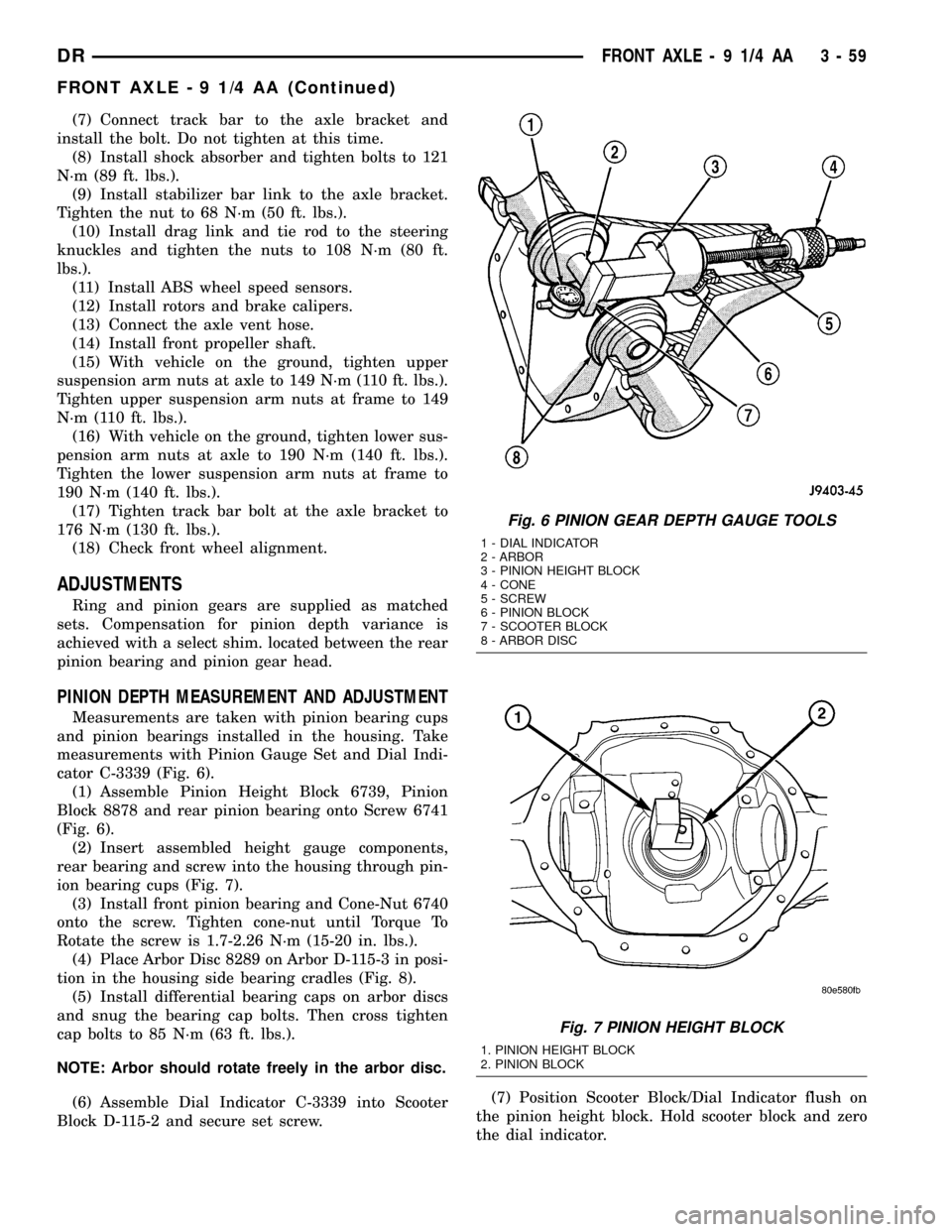
PINION DEPTH MEASUREMENT AND ADJUSTMENT
Measurements are taken with pinion bearing cups
and pinion bearings installed in the housing. Take
measurements with Pinion Gauge Set and Dial Indi-
cator C-3339 (Fig. 6).
(1) Assemble Pinion Height Block 6739, Pinion
Block 8878 and rear pinion bearing onto Screw 6741
(Fig. 6).
(2) Insert assembled height gauge components,
rear bearing and screw into the housing through pin-
ion bearing cups (Fig. 7).
(3) Install front pinion bearing and Cone-Nut 6740
onto the screw. Tighten cone-nut until Torque To
Rotate the screw is 1.7-2.26 N´m (15-20 in. lbs.).
(4) Place Arbor Disc 8289 on Arbor D-115-3 in posi-
tion in the housing side bearing cradles (Fig. 8).
(5) Install differential bearing caps on arbor discs
and snug the bearing cap bolts. Then cross tighten
cap bolts to 85 N´m (63 ft. lbs.).
NOTE: Arbor should rotate freely in the arbor disc.
(6) Assemble Dial Indicator C-3339 into Scooter
Block D-115-2 and secure set screw.(7) Position Scooter Block/Dial Indicator flush on
the pinion height block. Hold scooter block and zero
the dial indicator.
Fig. 6 PINION GEAR DEPTH GAUGE TOOLS
1 - DIAL INDICATOR
2 - ARBOR
3 - PINION HEIGHT BLOCK
4 - CONE
5 - SCREW
6 - PINION BLOCK
7 - SCOOTER BLOCK
8 - ARBOR DISC
Fig. 7 PINION HEIGHT BLOCK
1. PINION HEIGHT BLOCK
2. PINION BLOCK
DRFRONT AXLE - 9 1/4 AA 3 - 59
FRONT AXLE - 9 1/4 AA (Continued)
Page 142 of 2627
(9) Loosen pinion gear side adjuster until it is no
longer in contact with the bearing cup, then tighten
it until it makes contact.
(10) Tighten pinion gear side adjuster an addi-
tional:
²New Bearings:6 Adjuster Holes
²Original Bearings:4 Adjuster Holes
(11) Install pinion gear side adjuster lock and bolt.
Do not tighten adjuster lock bolt at this time.
(12) Tighten bearing cap bolts to 85 N´m (63 ft.
lbs.).
(13) Tighten adjuster lock bolts to 25 N´m (18 ft.
lbs.).
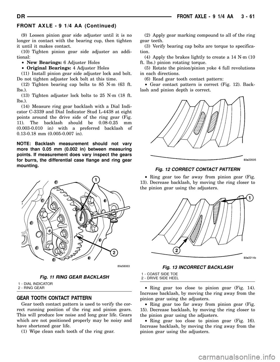
(14) Measure ring gear backlash with a Dial Indi-
cator C-3339 and Dial Indicator Stud L-4438 at eight
points around the drive side of the ring gear (Fig.
11). The backlash should be 0.08-0.25 mm
(0.003-0.010 in) with a preferred backlash of
0.13-0.18 mm (0.005-0.007 in).
NOTE: Backlash measurement should not vary
more than 0.05 mm (0.002 in) between measuring
points. If measurement does vary inspect the gears
for burrs, the differential case flange and ring gear
mounting.
GEAR TOOTH CONTACT PATTERN
Gear tooth contact pattern is used to verify the cor-
rect running position of the ring and pinion gears.
This will produce low noise and long gear life. Gears
which are not positioned properly may be noisy and
have shortened gear life.
(1) Wipe clean each tooth of the ring gear.(2) Apply gear marking compound to all of the ring
gear teeth.
(3) Verify bearing cap bolts are torque to specifica-
tion.
(4) Apply the brakes lightly to create a 14 N´m (10
ft. lbs.) pinion rotating torque.
(5) Rotate the pinion/pinion yoke 4 full revolutions
in each directions.
(6) Read gear tooth contact pattern:
²Gear contact pattern is correct (Fig. 12). Back-
lash and pinion depth is correct.
²Ring gear too far away from pinion gear (Fig.
13). Decrease backlash, by moving the ring closer to
the pinion gear using the adjusters.
²Ring gear too close to pinion gear (Fig. 14).
Increase backlash, by moving the ring away from the
pinion gear using the adjusters.
²Ring gear too far away from pinion gear (Fig.
15). Decrease backlash, by moving the ring closer to
the pinion gear using the adjusters.
²Ring gear too close to pinion gear (Fig. 16).
Increase backlash, by moving the ring away from the
pinion gear using the adjusters.
Fig. 11 RING GEAR BACKLASH
1 - DIAL INDICATOR
2 - RING GEAR
Fig. 12 CORRECT CONTACT PATTERN
Fig. 13 INCORRECT BACKLASH
1 - COAST SIDE TOE
2 - DRIVE SIDE HEEL
DRFRONT AXLE - 9 1/4 AA 3 - 61
FRONT AXLE - 9 1/4 AA (Continued)