DODGE RAM 1500 1998 2.G Manual PDF
Manufacturer: DODGE, Model Year: 1998, Model line: RAM 1500, Model: DODGE RAM 1500 1998 2.GPages: 2627
Page 71 of 2627
UPPER BALL JOINT
DIAGNOSIS AND TESTING - UPPER BALL
JOINT
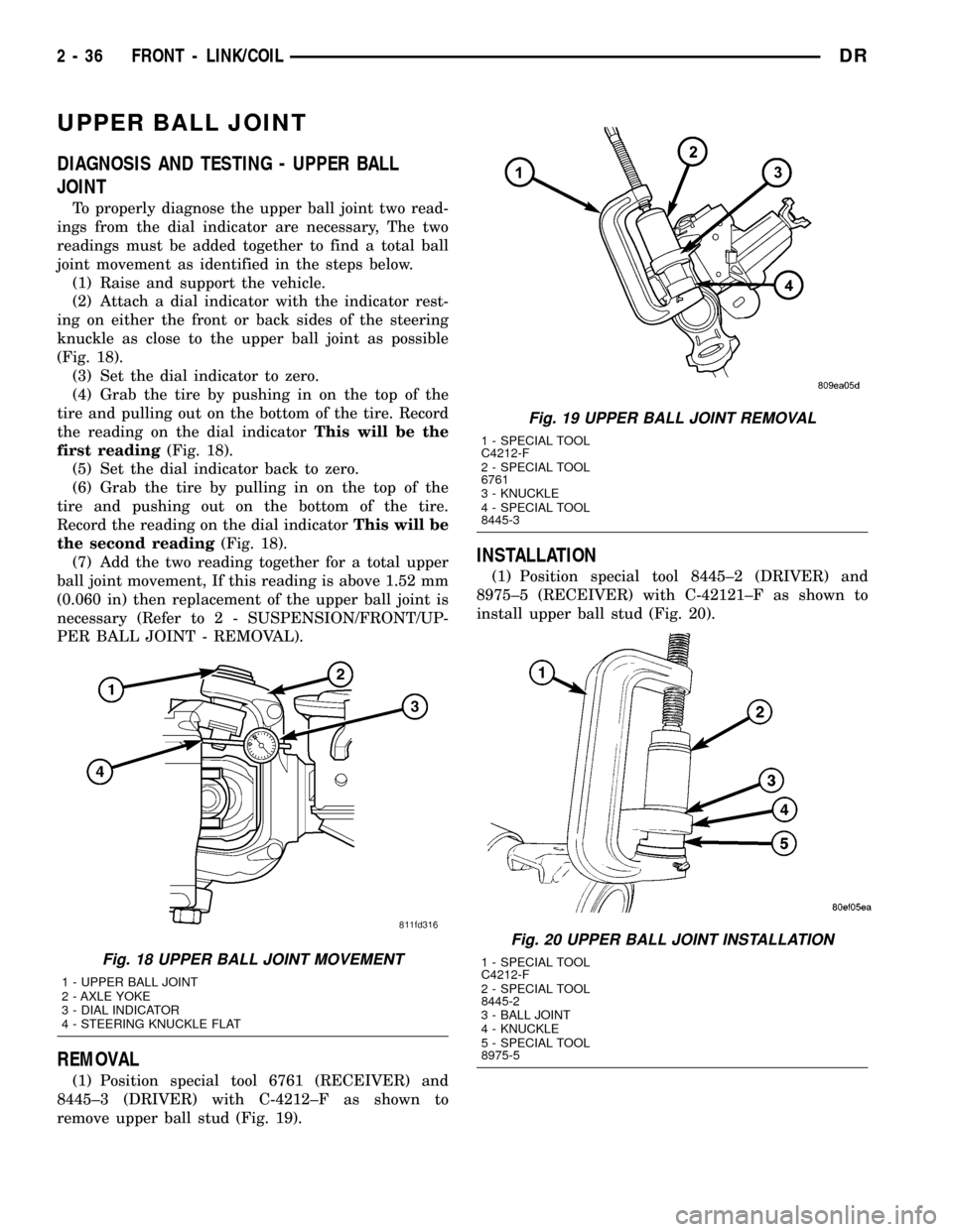
To properly diagnose the upper ball joint two read-
ings from the dial indicator are necessary, The two
readings must be added together to find a total ball
joint movement as identified in the steps below.
(1) Raise and support the vehicle.
(2) Attach a dial indicator with the indicator rest-
ing on either the front or back sides of the steering
knuckle as close to the upper ball joint as possible
(Fig. 18).
(3) Set the dial indicator to zero.
(4) Grab the tire by pushing in on the top of the
tire and pulling out on the bottom of the tire. Record
the reading on the dial indicatorThis will be the
first reading(Fig. 18).
(5) Set the dial indicator back to zero.
(6) Grab the tire by pulling in on the top of the
tire and pushing out on the bottom of the tire.
Record the reading on the dial indicatorThis will be
the second reading(Fig. 18).
(7) Add the two reading together for a total upper
ball joint movement, If this reading is above 1.52 mm
(0.060 in) then replacement of the upper ball joint is
necessary (Refer to 2 - SUSPENSION/FRONT/UP-
PER BALL JOINT - REMOVAL).
REMOVAL
(1) Position special tool 6761 (RECEIVER) and
8445±3 (DRIVER) with C-4212±F as shown to
remove upper ball stud (Fig. 19).
INSTALLATION
(1) Position special tool 8445±2 (DRIVER) and
8975±5 (RECEIVER) with C-42121±F as shown to
install upper ball stud (Fig. 20).
Fig. 18 UPPER BALL JOINT MOVEMENT
1 - UPPER BALL JOINT
2 - AXLE YOKE
3 - DIAL INDICATOR
4 - STEERING KNUCKLE FLAT
Fig. 19 UPPER BALL JOINT REMOVAL
1 - SPECIAL TOOL
C4212-F
2 - SPECIAL TOOL
6761
3 - KNUCKLE
4 - SPECIAL TOOL
8445-3
Fig. 20 UPPER BALL JOINT INSTALLATION
1 - SPECIAL TOOL
C4212-F
2 - SPECIAL TOOL
8445-2
3 - BALL JOINT
4 - KNUCKLE
5 - SPECIAL TOOL
8975-5
2 - 36 FRONT - LINK/COILDR
Page 72 of 2627
KNUCKLE
REMOVAL
(1) Remove the hub bearing (Refer to 2 - SUSPEN-
SION/FRONT/HUB / BEARING - REMOVAL).
(2) Remove tie-rod or drag link end from the steer-
ing knuckle arm.
(3) Remove the ABS sensor wire and bracket from
knuckle. Refer to Brakes, for proper procedures.
(4) Remove the cotter pin from the upper ball stud
nut. Remove the upper and lower ball stud nuts.
(5) Strike the steering knuckle with a brass ham-
mer to loosen.
(6) Remove knuckle from axle tube yokes.
INSTALLATION
(1) Position the steering knuckle on the ball studs.
(2) Install and tighten lower ball stud nut to 47
N´m (35 ft. lbs.) torque. Do not install cotter pin at
this time.
(3) Install and tighten upper ball stud nut to 94
N´m (70 ft. lbs.) torque. Advance nut to next slot to
line up hole and install new cotter pin.
(4) Retorque lower ball stud nut to 190±217 N´m
(140±160 ft. lbs.) torque. Advance nut to next slot to
line up hole and install new cotter pin.
(5) Install the hub bearing (Refer to 2 - SUSPEN-
SION/FRONT/HUB / BEARING - INSTALLATION).
(6) Install tie-rod or drag link end onto the steer-
ing knuckle arm.
(7) Install the ABS sensor wire and bracket to the
knuckle. Refer to Brakes, for proper procedure.
UPPER SUSPENSION ARM
REMOVAL
REMOVAL - LEFT
(1) Raise and support the vehicle.
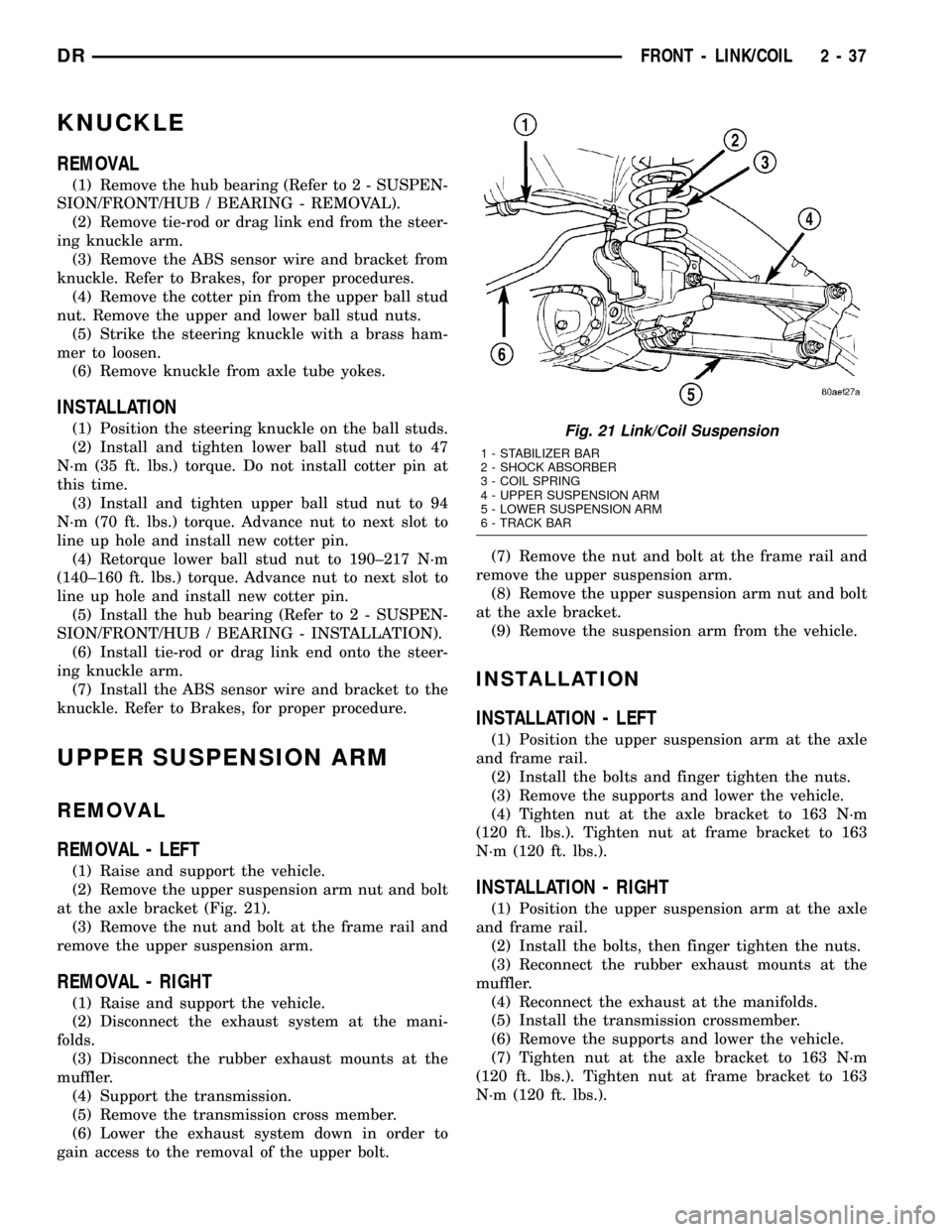
(2) Remove the upper suspension arm nut and bolt
at the axle bracket (Fig. 21).
(3) Remove the nut and bolt at the frame rail and
remove the upper suspension arm.
REMOVAL - RIGHT
(1) Raise and support the vehicle.
(2) Disconnect the exhaust system at the mani-
folds.
(3) Disconnect the rubber exhaust mounts at the
muffler.
(4) Support the transmission.
(5) Remove the transmission cross member.
(6) Lower the exhaust system down in order to
gain access to the removal of the upper bolt.(7) Remove the nut and bolt at the frame rail and
remove the upper suspension arm.
(8) Remove the upper suspension arm nut and bolt
at the axle bracket.
(9) Remove the suspension arm from the vehicle.
INSTALLATION
INSTALLATION - LEFT
(1) Position the upper suspension arm at the axle
and frame rail.
(2) Install the bolts and finger tighten the nuts.
(3) Remove the supports and lower the vehicle.
(4) Tighten nut at the axle bracket to 163 N´m
(120 ft. lbs.). Tighten nut at frame bracket to 163
N´m (120 ft. lbs.).
INSTALLATION - RIGHT
(1) Position the upper suspension arm at the axle
and frame rail.
(2) Install the bolts, then finger tighten the nuts.
(3) Reconnect the rubber exhaust mounts at the
muffler.
(4) Reconnect the exhaust at the manifolds.
(5) Install the transmission crossmember.
(6) Remove the supports and lower the vehicle.
(7) Tighten nut at the axle bracket to 163 N´m
(120 ft. lbs.). Tighten nut at frame bracket to 163
N´m (120 ft. lbs.).
Fig. 21 Link/Coil Suspension
1 - STABILIZER BAR
2 - SHOCK ABSORBER
3 - COIL SPRING
4 - UPPER SUSPENSION ARM
5 - LOWER SUSPENSION ARM
6 - TRACK BAR
DRFRONT - LINK/COIL 2 - 37
Page 73 of 2627

LOWER SUSPENSION ARM
REMOVAL
(1) Raise and support the vehicle.
(2) Paint or scribe alignment marks on the cam
adjusters and suspension arm for installation refer-
ence (Fig. 22).
(3) Remove the lower suspension arm nut, cam
and cam bolt from the axle.
(4) Remove the nut and bolt from the frame rail
bracket and remove the lower suspension arm (Fig.
22).
INSTALLATION
(1) Position the lower suspension arm at the axle
bracket and frame rail bracket.
(2) Install the rear bolt and finger tighten the nut.
(3) Install the cam bolt, cam and nut in the axle
and align the reference marks.
(4) Remove support and lower the vehicle.
(5) Tighten cam nut at the axle bracket to 217
N´m (160 ft. lbs.). Tighten rear nut at the frame
bracket to 217 N´m (160 ft. lbs.).
SHOCK
DIAGNOSIS AND TESTING - SHOCK
A knocking or rattling noise from a shock absorber
may be caused by movement between mounting
bushings and metal brackets or attaching compo-
nents. These noises can usually be stopped by tight-
ening the attaching nuts. If the noise persists,
inspect for damaged and worn bushings, and attach-
ing components. Repair as necessary if any of these
conditions exist.
A squeaking noise from the shock absorber may be
caused by the hydraulic valving and may be intermit-
tent. This condition is not repairable and the shock
absorber must be replaced.
The shock absorbers are not refillable or adjust-
able. If a malfunction occurs, the shock absorber
must be replaced. To test a shock absorber, hold it in
an upright position and force the piston in and out of
the cylinder four or five times. The action throughout
each stroke should be smooth and even.
The shock absorber bushings do not require any
type of lubrication. Do not attempt to stop bushing
noise by lubricating them. Grease and mineral oil-
base lubricants will deteriorate the bushing.
REMOVAL
(1) Remove the nut, retainer and grommet from
the upper stud in the engine compartment.
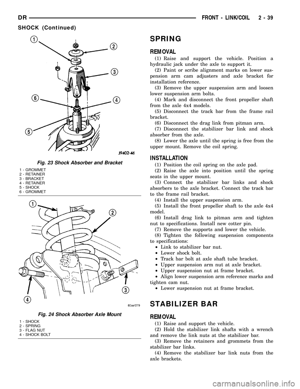
(2) Remove three nuts from the upper shock
bracket (Fig. 23).
(3) Remove the lower bolt from the axle bracket
(Fig. 24). Remove the shock absorber from engine
compartment.
INSTALLATION
(1) Position the lower retainer and grommet on the
upper stud. Insert the shock absorber through the
spring from engine compartment.
(2) Install the lower bolt and tighten to 135 N´m
(100 ft. lbs.).
(3) Install the upper shock bracket and three nuts.
Tighten nuts to 75 N´m (55 ft. lbs.).
(4) Install upper grommet and retainer. Install
upper shock nut and tighten to 54 N´m (40 ft. lbs).
Fig. 22 Adjustment Cam
1 - ADJUSTMENT CAM
2 - AXLE BRACKET
3 - BRACKET REINFORCEMENT
4 - LOWER SUSPENSION ARM
2 - 38 FRONT - LINK/COILDR
Page 74 of 2627
SPRING
REMOVAL
(1) Raise and support the vehicle. Position a
hydraulic jack under the axle to support it.
(2) Paint or scribe alignment marks on lower sus-
pension arm cam adjusters and axle bracket for
installation reference.
(3) Remove the upper suspension arm and loosen
lower suspension arm bolts.
(4) Mark and disconnect the front propeller shaft
from the axle 4x4 models.
(5) Disconnect the track bar from the frame rail
bracket.
(6) Disconnect the drag link from pitman arm.
(7) Disconnect the stabilizer bar link and shock
absorber from the axle.
(8) Lower the axle until the spring is free from the
upper mount. Remove the coil spring.
INSTALLATION
(1) Position the coil spring on the axle pad.
(2) Raise the axle into position until the spring
seats in the upper mount.
(3) Connect the stabilizer bar links and shock
absorbers to the axle bracket. Connect the track bar
to the frame rail bracket.
(4) Install the upper suspension arm.
(5) Install the front propeller shaft to the axle 4x4
model.
(6) Install drag link to pitman arm and tighten
nut to specifications. Install new cotter pin.
(7) Remove the supports and lower the vehicle.
(8) Tighten the following suspension components
to specifications:
²Link to stabilizer bar nut.
²Lower shock bolt.
²Track bar bolt at axle shaft tube bracket.
²Upper suspension arm nut at axle bracket.
²Upper suspension nut at frame bracket.
²Align lower suspension arm reference marks and
tighten cam nut.
²Lower suspension nut at frame bracket.
STABILIZER BAR
REMOVAL
(1) Raise and support the vehicle.
(2) Hold the stabilizer link shafts with a wrench
and remove the link nuts at the stabilizer bar.
(3) Remove the retainers and grommets from the
stabilizer bar links.
(4) Remove the stabilizer bar link nuts from the
axle brackets.
Fig. 23 Shock Absorber and Bracket
1 - GROMMET
2 - RETAINER
3 - BRACKET
4 - RETAINER
5 - SHOCK
6 - GROMMET
Fig. 24 Shock Absorber Axle Mount
1 - SHOCK
2 - SPRING
3 - FLAG NUT
4 - SHOCK BOLT
DRFRONT - LINK/COIL 2 - 39
SHOCK (Continued)
Page 75 of 2627

(5) Remove the links from the axle brackets with
Puller C-3894-A (Fig. 25).
(6) Remove the stabilizer bar clamps from the
frame rails and remove the stabilizer bar.INSTALLATION
(1) Position the stabilizer bar on the frame rail
and install the clamps and bolts. Ensure the bar is
centered with equal spacing on both sides.
(2) Tighten the clamp bolts to 61 N´m (45 ft. lbs.).
(3) Install links to the axle bracket and tighten
nut to 71 N´m (52 ft. lbs.).
(4) Install links, retainers, grommets and nuts to
the stabilizer bar. Hold the link shaft with a wrench
and tighten the nuts to 37 N´m (27 ft. lbs.).
(5) Remove the supports and lower the vehicle.
Fig. 25 Stabilizer Link
1 - PULLER
2 - LINK
2 - 40 FRONT - LINK/COILDR
STABILIZER BAR (Continued)
Page 76 of 2627

REAR
TABLE OF CONTENTS
page page
REAR
DESCRIPTION.........................41
DIAGNOSIS AND TESTING - SPRING AND
SHOCK.............................41
SPECIFICATIONS
TORQUE CHART......................42
BUSHINGS
REMOVAL.............................43
INSTALLATION.........................43
JOUNCE BUMPER
REMOVAL.............................43
INSTALLATION.........................43
AUXILIARY SPRING BUMPERS (3500)
REMOVAL.............................43INSTALLATION.........................43
SHOCK
REMOVAL.............................43
INSTALLATION.........................43
SPRING
DESCRIPTION.........................44
OPERATION...........................44
REMOVAL.............................44
INSTALLATION.........................44
SPRING TIP INSERTS
REMOVAL.............................44
INSTALLATION.........................45
REAR
DESCRIPTION
The rear suspension is comprised of:
²Shock Absorbers
²Jounce Bumpers
²Leaf Springs
²Auxiliary Leaf Spring (3500 series)
²Auxiliary Spring Bumpers (3500 series)
²Drive Axle
CAUTION: A vehicle should always be loaded so
the vehicle weight center-line is located immedi-
ately forward of the rear axle. Correct vehicle load-
ing provides proper front tire-to-road contact. This
results in maximum vehicle handling stability and
safety. Incorrect vehicle weight distribution can
cause excessive tire tread wear, spring fatigue or
failure, and erratic steering.
CAUTION: Suspension components with rubber/ure-
thane bushings (except stabilizer bar) should be
tightened with the vehicle at normal ride height. It is
important to have the springs supporting the weight
of the vehicle when the fasteners are torqued. If
springs are not at their normal ride position, vehicle
ride comfort could be affected and premature bush-
ing wear may occur.
DIAGNOSIS AND TESTING - SPRING AND
SHOCK
A knocking or rattling noise from a shock absorber
may be caused by movement between mounting
bushings and metal brackets or attaching compo-
nents. These noises can usually be stopped by tight-
ening the attaching nuts. If the noise persists,
inspect for damaged and worn bushings, and attach-
ing components. Repair as necessary if any of these
conditions exist.
A squeaking noise from the shock absorber may be
caused by the hydraulic valving and may be intermit-
tent. This condition is not repairable and the shock
absorber must be replaced.
The shock absorbers are not refillable or adjust-
able. If a malfunction occurs, the shock absorber
must be replaced. To test a shock absorber, hold it in
an upright position and force the piston in and out of
the cylinder four or five times. The action throughout
each stroke should be smooth and even.
The spring eye and shock absorber bushings do not
require any type of lubrication. Do not attempt to
stop spring bushing noise by lubricating them.
Grease and mineral oil-base lubricants will deterio-
rate the bushing rubber.
If the vehicle is used for severe, off-road operation,
the springs should be examined periodically. Check
for broken and shifted leafs, loose and missing clips,
and broken center bolts. Refer to Spring and Shock
Absorber Diagnosis chart for additional information.
DRREAR 2 - 41
Page 77 of 2627
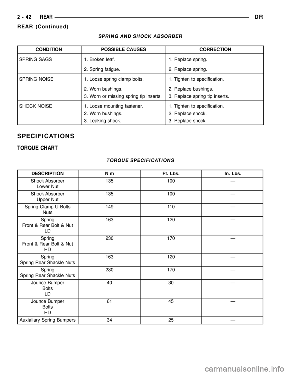
SPRING AND SHOCK ABSORBER
CONDITION POSSIBLE CAUSES CORRECTION
SPRING SAGS 1. Broken leaf. 1. Replace spring.
2. Spring fatigue. 2. Replace spring.
SPRING NOISE 1. Loose spring clamp bolts. 1. Tighten to specification.
2. Worn bushings. 2. Replace bushings.
3. Worn or missing spring tip inserts. 3. Replace spring tip inserts.
SHOCK NOISE 1. Loose mounting fastener. 1. Tighten to specification.
2. Worn bushings. 2. Replace shock.
3. Leaking shock. 3. Replace shock.
SPECIFICATIONS
TORQUE CHART
TORQUE SPECIFICATIONS
DESCRIPTION N´m Ft. Lbs. In. Lbs.
Shock Absorber
Lower Nut135 100 Ð
Shock Absorber
Upper Nut135 100 Ð
Spring Clamp U-Bolts
Nuts149 110 Ð
Spring
Front & Rear Bolt & Nut
LD163 120 Ð
Spring
Front & Rear Bolt & Nut
HD230 170 Ð
Spring
Spring Rear Shackle Nuts163 120 Ð
Spring
Spring Rear Shackle Nuts230 170 Ð
Jounce Bumper
Bolts
LD40 30 Ð
Jounce Bumper
Bolts
HD61 45 Ð
Auxialiary Spring Bumpers 34 25 Ð
2 - 42 REARDR
REAR (Continued)
Page 78 of 2627
BUSHINGS
REMOVAL
(1) Remove the spring from the vehicle.
(2) Make small relief cuts in the flared up end of
the bushing metal being careful not to cut the spring.
Use a punch to bend the flared bushing metal down
for push out.
(3) Position the spring eye in a press.
(4) Press the bushing out with an appropriate size
driver.
INSTALLATION
(1) Press new bushing into the spring eye with an
appropriate size driver. The bushing should be cen-
tered in the spring eye.
(2) Stake the outermetal of the bushing in a mini-
mum of six points to retain the bushing.
(3) Install the spring on the vehicle.
JOUNCE BUMPER
REMOVAL
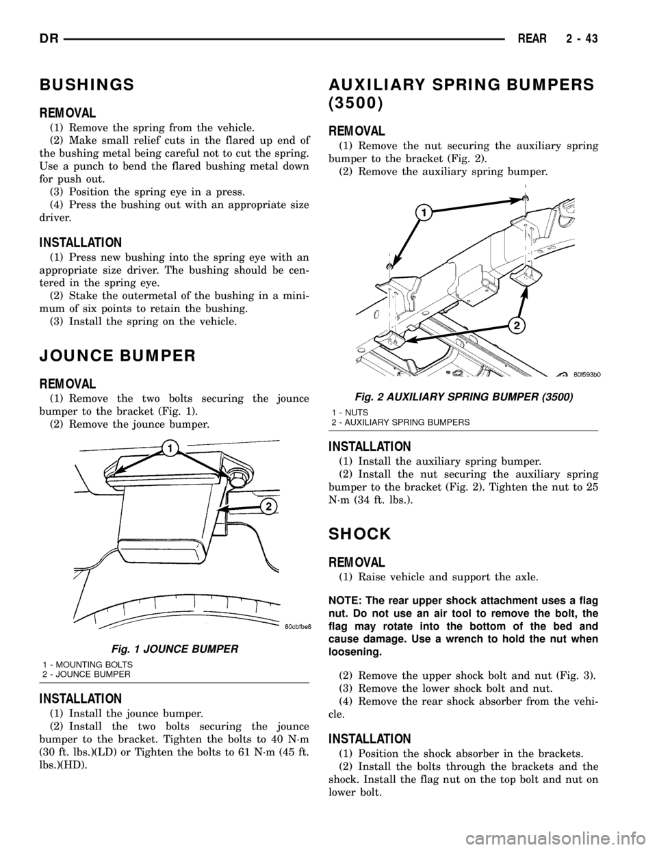
(1) Remove the two bolts securing the jounce
bumper to the bracket (Fig. 1).
(2) Remove the jounce bumper.
INSTALLATION
(1) Install the jounce bumper.
(2) Install the two bolts securing the jounce
bumper to the bracket. Tighten the bolts to 40 N´m
(30 ft. lbs.)(LD) or Tighten the bolts to 61 N´m (45 ft.
lbs.)(HD).
AUXILIARY SPRING BUMPERS
(3500)
REMOVAL
(1) Remove the nut securing the auxiliary spring
bumper to the bracket (Fig. 2).
(2) Remove the auxiliary spring bumper.
INSTALLATION
(1) Install the auxiliary spring bumper.
(2) Install the nut securing the auxiliary spring
bumper to the bracket (Fig. 2). Tighten the nut to 25
N´m (34 ft. lbs.).
SHOCK
REMOVAL
(1) Raise vehicle and support the axle.
NOTE: The rear upper shock attachment uses a flag
nut. Do not use an air tool to remove the bolt, the
flag may rotate into the bottom of the bed and
cause damage. Use a wrench to hold the nut when
loosening.
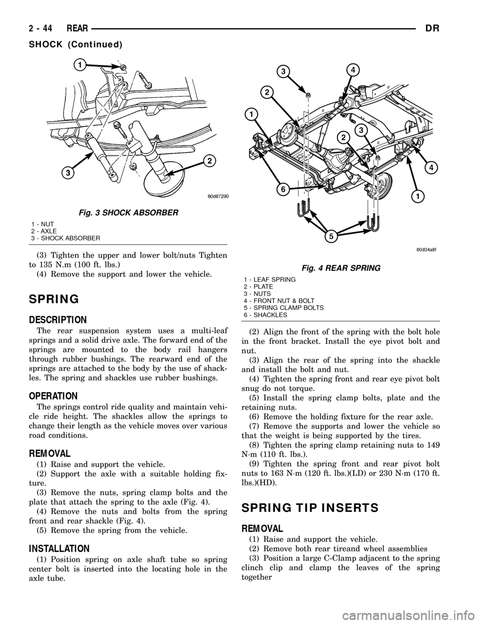
(2) Remove the upper shock bolt and nut (Fig. 3).
(3) Remove the lower shock bolt and nut.
(4) Remove the rear shock absorber from the vehi-
cle.
INSTALLATION
(1) Position the shock absorber in the brackets.
(2) Install the bolts through the brackets and the
shock. Install the flag nut on the top bolt and nut on
lower bolt.
Fig. 1 JOUNCE BUMPER
1 - MOUNTING BOLTS
2 - JOUNCE BUMPER
Fig. 2 AUXILIARY SPRING BUMPER (3500)
1 - NUTS
2 - AUXILIARY SPRING BUMPERS
DRREAR 2 - 43
Page 79 of 2627
(3) Tighten the upper and lower bolt/nuts Tighten
to 135 N.m (100 ft. lbs.)
(4) Remove the support and lower the vehicle.
SPRING
DESCRIPTION
The rear suspension system uses a multi-leaf
springs and a solid drive axle. The forward end of the
springs are mounted to the body rail hangers
through rubber bushings. The rearward end of the
springs are attached to the body by the use of shack-
les. The spring and shackles use rubber bushings.
OPERATION
The springs control ride quality and maintain vehi-
cle ride height. The shackles allow the springs to
change their length as the vehicle moves over various
road conditions.
REMOVAL
(1) Raise and support the vehicle.
(2) Support the axle with a suitable holding fix-
ture.
(3) Remove the nuts, spring clamp bolts and the
plate that attach the spring to the axle (Fig. 4).
(4) Remove the nuts and bolts from the spring
front and rear shackle (Fig. 4).
(5) Remove the spring from the vehicle.
INSTALLATION
(1) Position spring on axle shaft tube so spring
center bolt is inserted into the locating hole in the
axle tube.(2) Align the front of the spring with the bolt hole
in the front bracket. Install the eye pivot bolt and
nut.
(3) Align the rear of the spring into the shackle
and install the bolt and nut.
(4) Tighten the spring front and rear eye pivot bolt
snug do not torque.
(5) Install the spring clamp bolts, plate and the
retaining nuts.
(6) Remove the holding fixture for the rear axle.
(7) Remove the supports and lower the vehicle so
that the weight is being supported by the tires.
(8) Tighten the spring clamp retaining nuts to 149
N´m (110 ft. lbs.).
(9) Tighten the spring front and rear pivot bolt
nuts to 163 N´m (120 ft. lbs.)(LD) or 230 N´m (170 ft.
lbs.)(HD).
SPRING TIP INSERTS
REMOVAL
(1) Raise and support the vehicle.
(2) Remove both rear tireand wheel assemblies
(3) Position a large C-Clamp adjacent to the spring
clinch clip and clamp the leaves of the spring
together
Fig. 3 SHOCK ABSORBER
1 - NUT
2 - AXLE
3 - SHOCK ABSORBER
Fig. 4 REAR SPRING
1 - LEAF SPRING
2 - PLATE
3 - NUTS
4 - FRONT NUT & BOLT
5 - SPRING CLAMP BOLTS
6 - SHACKLES
2 - 44 REARDR
SHOCK (Continued)
Page 80 of 2627
CAUTION: When working on the front leaf spring
clinch clamps finish the front before starting on the
rear to prevent personal injury.
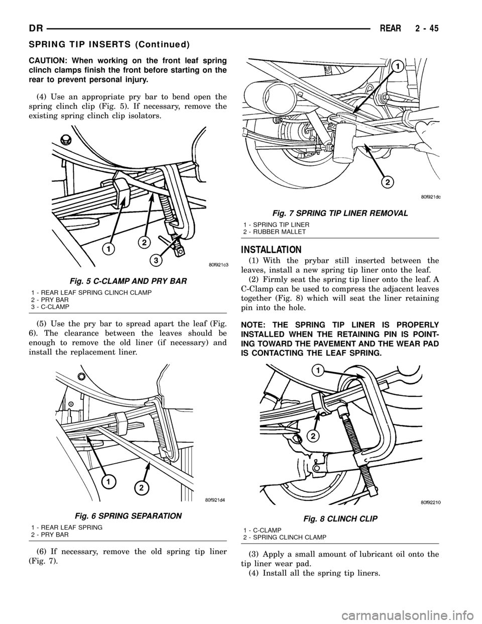
(4) Use an appropriate pry bar to bend open the
spring clinch clip (Fig. 5). If necessary, remove the
existing spring clinch clip isolators.
(5) Use the pry bar to spread apart the leaf (Fig.
6). The clearance between the leaves should be
enough to remove the old liner (if necessary) and
install the replacement liner.
(6) If necessary, remove the old spring tip liner
(Fig. 7).
INSTALLATION
(1) With the prybar still inserted between the
leaves, install a new spring tip liner onto the leaf.
(2) Firmly seat the spring tip liner onto the leaf. A
C-Clamp can be used to compress the adjacent leaves
together (Fig. 8) which will seat the liner retaining
pin into the hole.
NOTE: THE SPRING TIP LINER IS PROPERLY
INSTALLED WHEN THE RETAINING PIN IS POINT-
ING TOWARD THE PAVEMENT AND THE WEAR PAD
IS CONTACTING THE LEAF SPRING.
(3) Apply a small amount of lubricant oil onto the
tip liner wear pad.
(4) Install all the spring tip liners.
Fig. 5 C-CLAMP AND PRY BAR
1 - REAR LEAF SPRING CLINCH CLAMP
2-PRYBAR
3 - C-CLAMP
Fig. 6 SPRING SEPARATION
1 - REAR LEAF SPRING
2-PRYBAR
Fig. 7 SPRING TIP LINER REMOVAL
1 - SPRING TIP LINER
2 - RUBBER MALLET
Fig. 8 CLINCH CLIP
1 - C-CLAMP
2 - SPRING CLINCH CLAMP
DRREAR 2 - 45
SPRING TIP INSERTS (Continued)