DODGE RAM 1500 1998 2.G Manual Online
Manufacturer: DODGE, Model Year: 1998, Model line: RAM 1500, Model: DODGE RAM 1500 1998 2.GPages: 2627
Page 81 of 2627
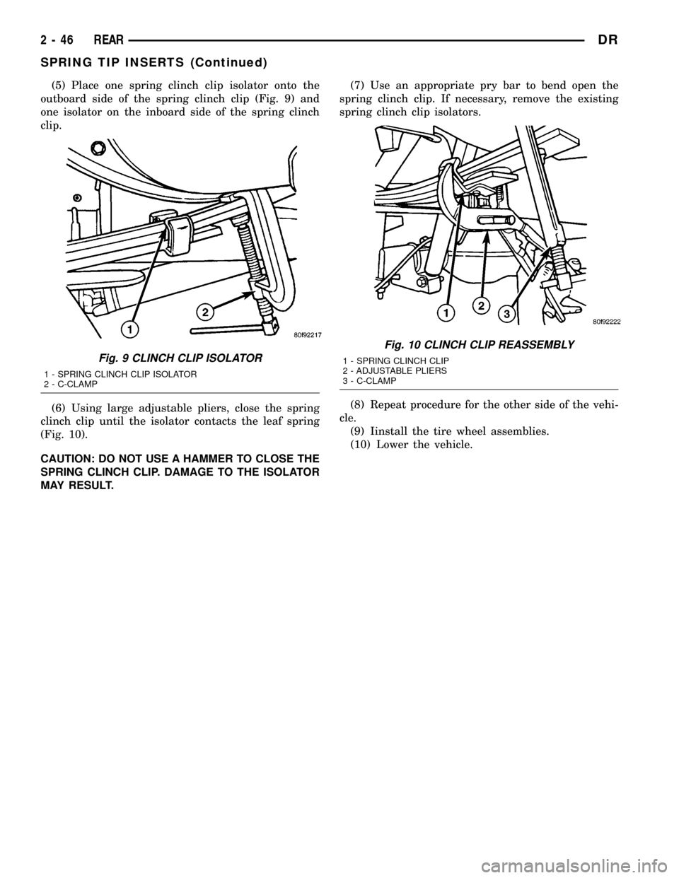
(5) Place one spring clinch clip isolator onto the
outboard side of the spring clinch clip (Fig. 9) and
one isolator on the inboard side of the spring clinch
clip.
(6) Using large adjustable pliers, close the spring
clinch clip until the isolator contacts the leaf spring
(Fig. 10).
CAUTION: DO NOT USE A HAMMER TO CLOSE THE
SPRING CLINCH CLIP. DAMAGE TO THE ISOLATOR
MAY RESULT.(7) Use an appropriate pry bar to bend open the
spring clinch clip. If necessary, remove the existing
spring clinch clip isolators.
(8) Repeat procedure for the other side of the vehi-
cle.
(9) Iinstall the tire wheel assemblies.
(10) Lower the vehicle.
Fig. 9 CLINCH CLIP ISOLATOR
1 - SPRING CLINCH CLIP ISOLATOR
2 - C-CLAMP
Fig. 10 CLINCH CLIP REASSEMBLY
1 - SPRING CLINCH CLIP
2 - ADJUSTABLE PLIERS
3 - C-CLAMP
2 - 46 REARDR
SPRING TIP INSERTS (Continued)
Page 82 of 2627
DIFFERENTIAL & DRIVELINE
TABLE OF CONTENTS
page page
PROPELLER SHAFT......................1
HALF SHAFT...........................20
FRONT AXLE - C205F....................27
FRONT AXLE - 9 1/4 AA...................54REAR AXLE-91/4.......................80
REAR AXLE - 10 1/2 AA..................112
REAR AXLE - 11 1/2 AA..................140
PROPELLER SHAFT
TABLE OF CONTENTS
page page
PROPELLER SHAFT
DIAGNOSIS AND TESTING................1
STANDARD PROCEDURE.................3
SPECIFICATIONS........................6
SPECIAL TOOLS........................6
PROPELLER SHAFT- LD FRONT
REMOVAL.............................6
INSTALLATION..........................7
PROPELLER SHAFT - HD FRONT
REMOVAL.............................7
INSTALLATION..........................7
REAR PROPELLER SHAFT
REMOVAL.............................8
INSTALLATION..........................8CENTER BEARING
REMOVAL.............................9
INSTALLATION..........................9
ADJUSTMENTS.........................9
SINGLE CARDAN UNIVERSAL JOINTS
DISASSEMBLY
DISASSEMBLY - WITH SNAP RINGS......10
DISASSEMBLY - WITH INJECTED RINGS . . . 11
ASSEMBLY
ASSEMBLY - WITH SNAP RINGS.........12
ASSEMBLY - WITH INJECTED RINGS......13
DOUBLE CARDAN UNIVERSAL JOINTS
DISASSEMBLY.........................16
ASSEMBLY............................17
PROPELLER SHAFT
DIAGNOSIS AND TESTING
PROPELLER SHAFT VIBRATION
Out-of-round tires or wheels that are out of bal-
ance, will cause a low frequency vibration.
Driveline vibration can also caused by loose or
damaged engine mounts.Propeller shaft vibration increases with vehicle
speed. A vibration that occurs at a specific speed
range, is not usually caused by an out of balance pro-
peller shaft. Defective universal joints or an incorrect
propeller shaft angle are usually the cause of such a
vibration.
DRDIFFERENTIAL & DRIVELINE 3 - 1
Page 83 of 2627
DRIVELINE VIBRATION
Drive Condition Possible Cause Correction
Propeller Shaft Noise 1) Undercoating or other foreign
material on shaft.1) Clean exterior of shaft and wash
with solvent.
2) Loose U-joint clamp screws. 2) Install new clamps and screws
and tighten to proper torque.
3) Loose or bent U-joint yoke or
excessive runout.3) Install new yoke.
4) Incorrect driveline angularity. 4) Measure and correct driveline
angles.
5) Rear spring center bolt not in
seat.5) Loosen spring u-bolts and seat
center bolt.
6) Worn U-joint bearings. 6) Install new U-joint.
7) Propeller shaft damaged or out
of balance.7) Installl new propeller shaft.
8) Broken rear spring. 8) Install new rear spring.
9) Excessive runout or unbalanced
condition.9) Re-index propeller shaft, test,
and evaluate.
10) Excessive drive pinion gear
shaft runout.10) Re-index propeller shaft and
evaluate.
11) Excessive axle yoke deflection. 11) Inspect and replace yoke if
necessary.
12) Excessive transfer case runout. 12) Inspect and repair as necessary.
Universal Joint Noise 1) Loose U-joint clamp screws. 1) Install new clamps and screws
and tighten to proper torque.
2) Lack of lubrication. 2) Replace as U-joints as
necessary.
PROPELLER SHAFT BALANCE
If propeller shaft is suspected of being out of bal-
ance, use the following procedure.
NOTE: Indexing propeller shaft 180É relative to the
yoke may eliminate some vibrations.
(1) Raise and support vehicle.
(2) Clean all foreign material from the propeller
shaft and universal joints.
(3) Inspect propeller shaft for missing balance
weights, broken welds and bent areas.If propeller
shaft is bent, it must be replaced.
(4) Inspect universal joints for wear and properly
installed.
(5) Check propeller shaft bolt torques.
(6) Remove wheels and install lug nuts to retain
brake rotors.
(7) Mark and number the shaft six inches from the
pinion yoke end at four positions 90É apart.
(8) Run and accelerate vehicle until vibration
occurs. Note the intensity and speed the vibration
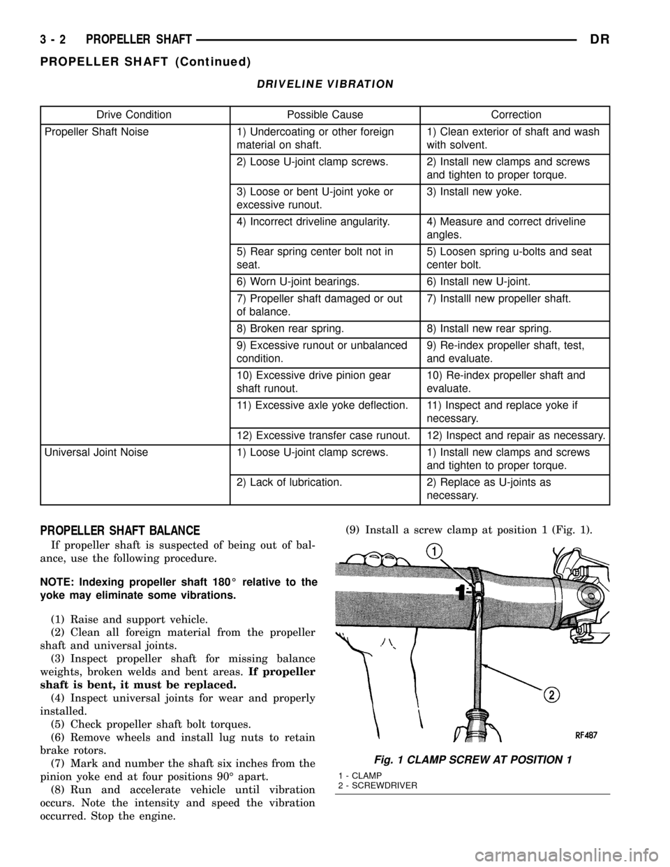
occurred. Stop the engine.(9) Install a screw clamp at position 1 (Fig. 1).
Fig. 1 CLAMP SCREW AT POSITION 1
1 - CLAMP
2 - SCREWDRIVER
3 - 2 PROPELLER SHAFTDR
PROPELLER SHAFT (Continued)
Page 84 of 2627
(10) Start engine and check vibration. If there is
little or no change move the clamp to the next posi-
tions. Repeat the vibration test.
NOTE: If there is no difference in vibration at this
positions, the vibration may not be the propeller
shaft.
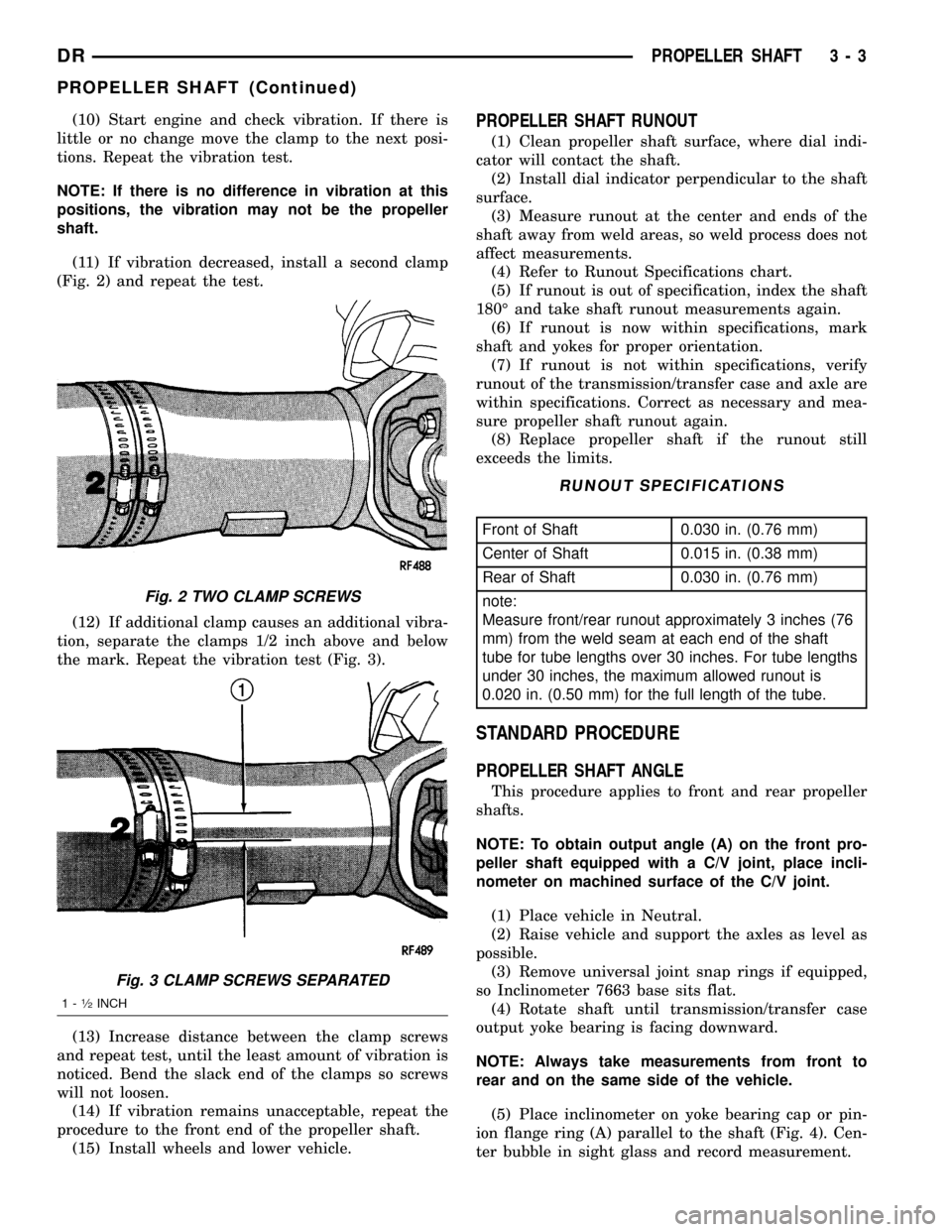
(11) If vibration decreased, install a second clamp
(Fig. 2) and repeat the test.
(12) If additional clamp causes an additional vibra-
tion, separate the clamps 1/2 inch above and below
the mark. Repeat the vibration test (Fig. 3).
(13) Increase distance between the clamp screws
and repeat test, until the least amount of vibration is
noticed. Bend the slack end of the clamps so screws
will not loosen.
(14) If vibration remains unacceptable, repeat the
procedure to the front end of the propeller shaft.
(15) Install wheels and lower vehicle.PROPELLER SHAFT RUNOUT
(1) Clean propeller shaft surface, where dial indi-
cator will contact the shaft.
(2) Install dial indicator perpendicular to the shaft
surface.
(3) Measure runout at the center and ends of the
shaft away from weld areas, so weld process does not
affect measurements.
(4) Refer to Runout Specifications chart.
(5) If runout is out of specification, index the shaft
180É and take shaft runout measurements again.
(6) If runout is now within specifications, mark
shaft and yokes for proper orientation.
(7) If runout is not within specifications, verify
runout of the transmission/transfer case and axle are
within specifications. Correct as necessary and mea-
sure propeller shaft runout again.
(8) Replace propeller shaft if the runout still
exceeds the limits.
RUNOUT SPECIFICATIONS
Front of Shaft 0.030 in. (0.76 mm)
Center of Shaft 0.015 in. (0.38 mm)
Rear of Shaft 0.030 in. (0.76 mm)
note:
Measure front/rear runout approximately 3 inches (76
mm) from the weld seam at each end of the shaft
tube for tube lengths over 30 inches. For tube lengths
under 30 inches, the maximum allowed runout is
0.020 in. (0.50 mm) for the full length of the tube.
STANDARD PROCEDURE
PROPELLER SHAFT ANGLE
This procedure applies to front and rear propeller
shafts.
NOTE: To obtain output angle (A) on the front pro-
peller shaft equipped with a C/V joint, place incli-
nometer on machined surface of the C/V joint.
(1) Place vehicle in Neutral.
(2) Raise vehicle and support the axles as level as
possible.
(3) Remove universal joint snap rings if equipped,
so Inclinometer 7663 base sits flat.
(4) Rotate shaft until transmission/transfer case
output yoke bearing is facing downward.
NOTE: Always take measurements from front to
rear and on the same side of the vehicle.
(5) Place inclinometer on yoke bearing cap or pin-
ion flange ring (A) parallel to the shaft (Fig. 4). Cen-
ter bubble in sight glass and record measurement.
Fig. 2 TWO CLAMP SCREWS
Fig. 3 CLAMP SCREWS SEPARATED
1-1¤2INCH
DRPROPELLER SHAFT 3 - 3
PROPELLER SHAFT (Continued)
Page 85 of 2627
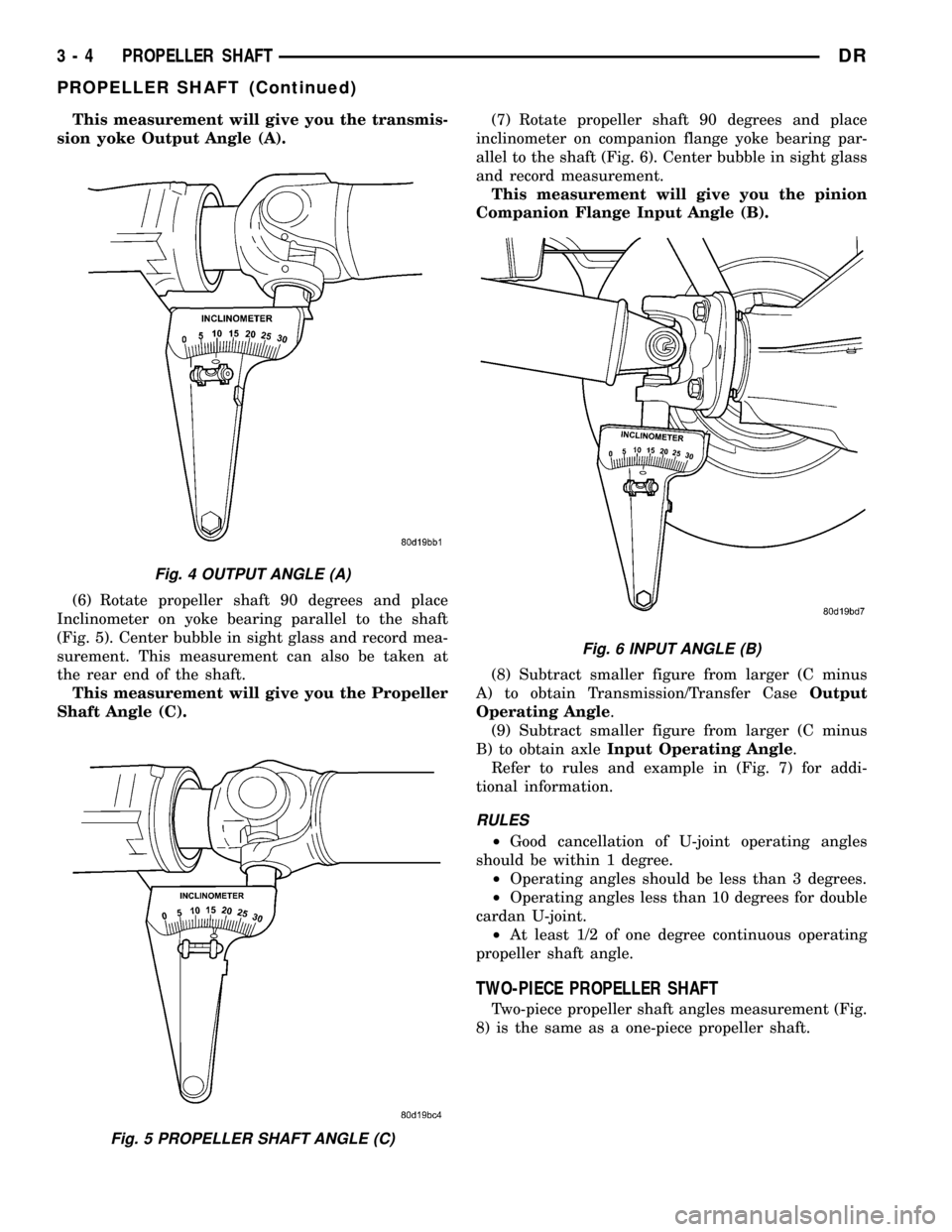
This measurement will give you the transmis-
sion yoke Output Angle (A).
(6) Rotate propeller shaft 90 degrees and place
Inclinometer on yoke bearing parallel to the shaft
(Fig. 5). Center bubble in sight glass and record mea-
surement. This measurement can also be taken at
the rear end of the shaft.
This measurement will give you the Propeller
Shaft Angle (C).(7) Rotate propeller shaft 90 degrees and place
inclinometer on companion flange yoke bearing par-
allel to the shaft (Fig. 6). Center bubble in sight glass
and record measurement.
This measurement will give you the pinion
Companion Flange Input Angle (B).
(8) Subtract smaller figure from larger (C minus
A) to obtain Transmission/Transfer CaseOutput
Operating Angle.
(9) Subtract smaller figure from larger (C minus
B) to obtain axleInput Operating Angle.
Refer to rules and example in (Fig. 7) for addi-
tional information.
RULES
²Good cancellation of U-joint operating angles
should be within 1 degree.
²Operating angles should be less than 3 degrees.
²Operating angles less than 10 degrees for double
cardan U-joint.
²At least 1/2 of one degree continuous operating
propeller shaft angle.
TWO-PIECE PROPELLER SHAFT
Two-piece propeller shaft angles measurement (Fig.
8) is the same as a one-piece propeller shaft.
Fig. 4 OUTPUT ANGLE (A)
Fig. 5 PROPELLER SHAFT ANGLE (C)
Fig. 6 INPUT ANGLE (B)
3 - 4 PROPELLER SHAFTDR
PROPELLER SHAFT (Continued)
Page 86 of 2627
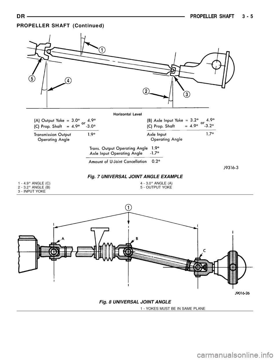
Fig. 7 UNIVERSAL JOINT ANGLE EXAMPLE
1 - 4.9É ANGLE (C)
2 - 3.2É ANGLE (B)
3 - INPUT YOKE4 - 3.0É ANGLE (A)
5 - OUTPUT YOKE
Fig. 8 UNIVERSAL JOINT ANGLE
1 - YOKES MUST BE IN SAME PLANE
DRPROPELLER SHAFT 3 - 5
PROPELLER SHAFT (Continued)
Page 87 of 2627
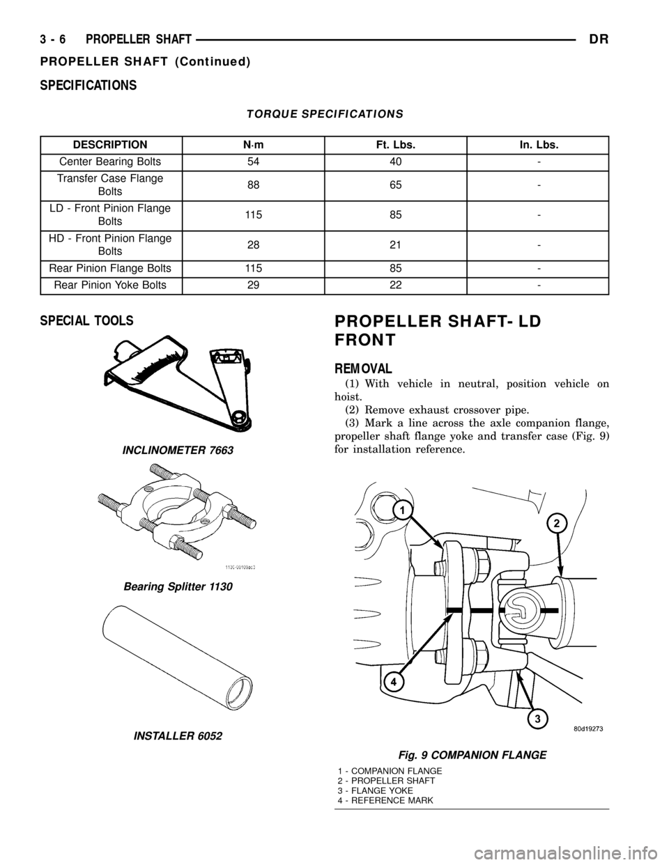
SPECIFICATIONS
TORQUE SPECIFICATIONS
DESCRIPTION N´m Ft. Lbs. In. Lbs.
Center Bearing Bolts 54 40 -
Transfer Case Flange
Bolts88 65 -
LD - Front Pinion Flange
Bolts11 5 8 5 -
HD - Front Pinion Flange
Bolts28 21 -
Rear Pinion Flange Bolts 115 85 -
Rear Pinion Yoke Bolts 29 22 -
SPECIAL TOOLSPROPELLER SHAFT- LD
FRONT
REMOVAL
(1) With vehicle in neutral, position vehicle on
hoist.
(2) Remove exhaust crossover pipe.
(3) Mark a line across the axle companion flange,
propeller shaft flange yoke and transfer case (Fig. 9)
for installation reference.
INCLINOMETER 7663
Bearing Splitter 1130
INSTALLER 6052
Fig. 9 COMPANION FLANGE
1 - COMPANION FLANGE
2 - PROPELLER SHAFT
3 - FLANGE YOKE
4 - REFERENCE MARK
3 - 6 PROPELLER SHAFTDR
PROPELLER SHAFT (Continued)
Page 88 of 2627
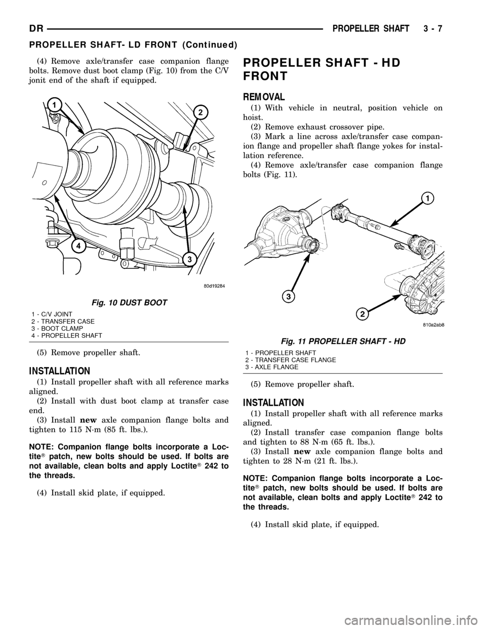
(4) Remove axle/transfer case companion flange
bolts. Remove dust boot clamp (Fig. 10) from the C/V
jonit end of the shaft if equipped.
(5) Remove propeller shaft.
INSTALLATION
(1) Install propeller shaft with all reference marks
aligned.
(2) Install with dust boot clamp at transfer case
end.
(3) Installnewaxle companion flange bolts and
tighten to 115 N´m (85 ft. lbs.).
NOTE: Companion flange bolts incorporate a Loc-
titeTpatch, new bolts should be used. If bolts are
not available, clean bolts and apply LoctiteT242 to
the threads.
(4) Install skid plate, if equipped.
PROPELLER SHAFT - HD
FRONT
REMOVAL
(1) With vehicle in neutral, position vehicle on
hoist.
(2) Remove exhaust crossover pipe.
(3) Mark a line across axle/transfer case compan-
ion flange and propeller shaft flange yokes for instal-
lation reference.
(4) Remove axle/transfer case companion flange
bolts (Fig. 11).
(5) Remove propeller shaft.
INSTALLATION
(1) Install propeller shaft with all reference marks
aligned.
(2) Install transfer case companion flange bolts
and tighten to 88 N´m (65 ft. lbs.).
(3) Installnewaxle companion flange bolts and
tighten to 28 N´m (21 ft. lbs.).
NOTE: Companion flange bolts incorporate a Loc-
titeTpatch, new bolts should be used. If bolts are
not available, clean bolts and apply LoctiteT242 to
the threads.
(4) Install skid plate, if equipped.
Fig. 10 DUST BOOT
1 - C/V JOINT
2 - TRANSFER CASE
3 - BOOT CLAMP
4 - PROPELLER SHAFT
Fig. 11 PROPELLER SHAFT - HD
1 - PROPELLER SHAFT
2 - TRANSFER CASE FLANGE
3 - AXLE FLANGE
DRPROPELLER SHAFT 3 - 7
PROPELLER SHAFT- LD FRONT (Continued)
Page 89 of 2627
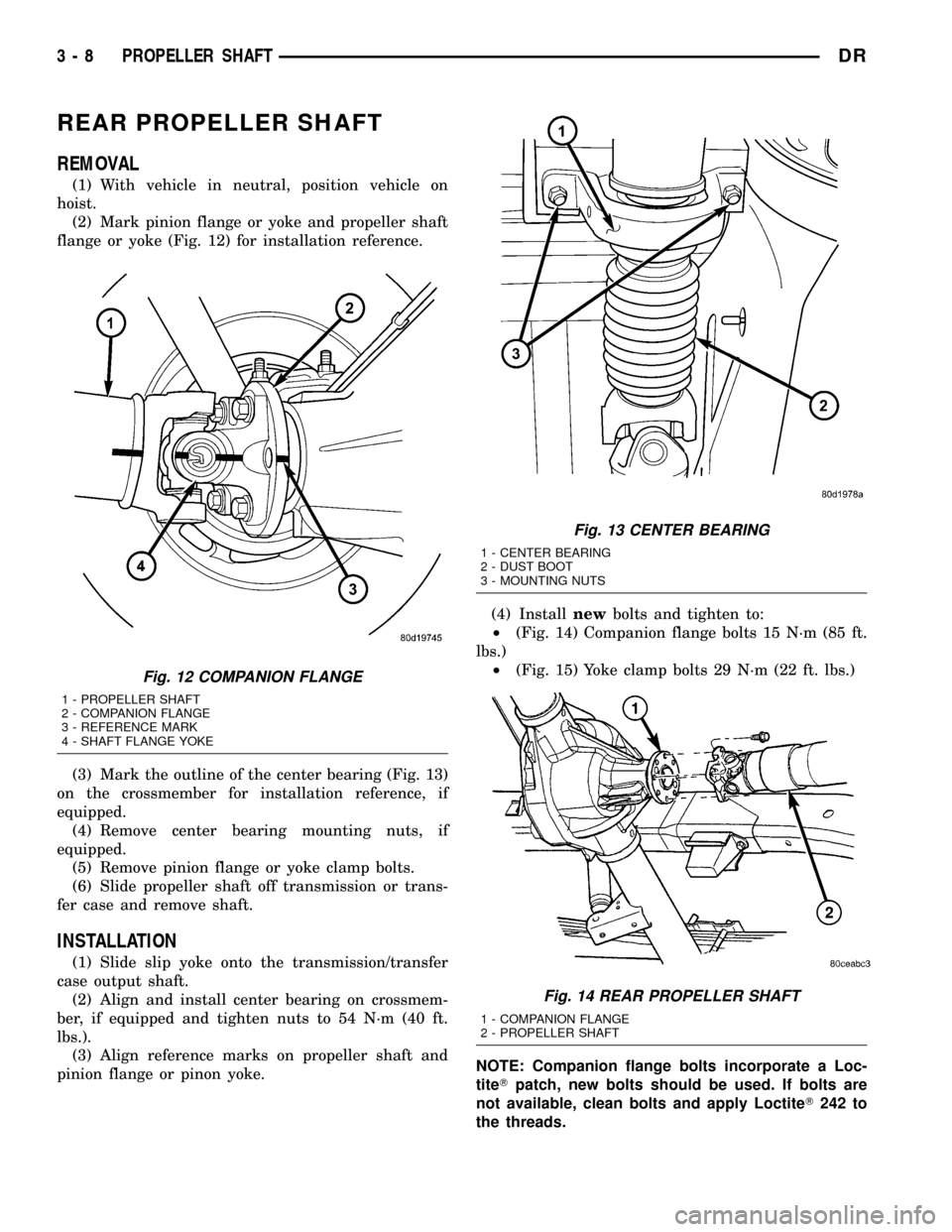
REAR PROPELLER SHAFT
REMOVAL
(1) With vehicle in neutral, position vehicle on
hoist.
(2) Mark pinion flange or yoke and propeller shaft
flange or yoke (Fig. 12) for installation reference.
(3) Mark the outline of the center bearing (Fig. 13)
on the crossmember for installation reference, if
equipped.
(4) Remove center bearing mounting nuts, if
equipped.
(5) Remove pinion flange or yoke clamp bolts.
(6) Slide propeller shaft off transmission or trans-
fer case and remove shaft.
INSTALLATION
(1) Slide slip yoke onto the transmission/transfer
case output shaft.
(2) Align and install center bearing on crossmem-
ber, if equipped and tighten nuts to 54 N´m (40 ft.
lbs.).
(3) Align reference marks on propeller shaft and
pinion flange or pinon yoke.(4) Installnewbolts and tighten to:
²(Fig. 14) Companion flange bolts 15 N´m (85 ft.
lbs.)
²(Fig. 15) Yoke clamp bolts 29 N´m (22 ft. lbs.)
NOTE: Companion flange bolts incorporate a Loc-
titeTpatch, new bolts should be used. If bolts are
not available, clean bolts and apply LoctiteT242 to
the threads.
Fig. 12 COMPANION FLANGE
1 - PROPELLER SHAFT
2 - COMPANION FLANGE
3 - REFERENCE MARK
4 - SHAFT FLANGE YOKE
Fig. 13 CENTER BEARING
1 - CENTER BEARING
2 - DUST BOOT
3 - MOUNTING NUTS
Fig. 14 REAR PROPELLER SHAFT
1 - COMPANION FLANGE
2 - PROPELLER SHAFT
3 - 8 PROPELLER SHAFTDR
Page 90 of 2627
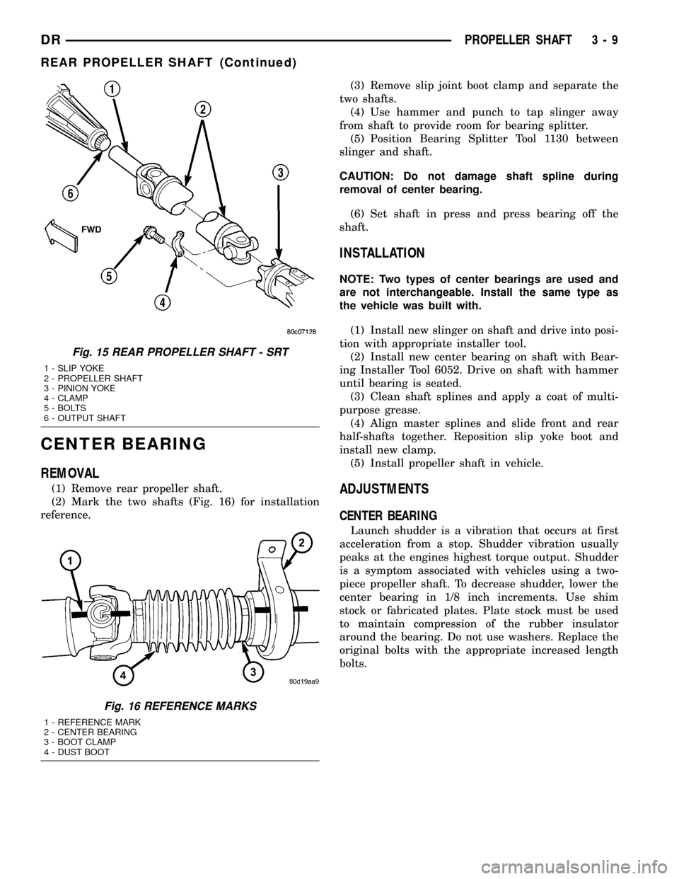
CENTER BEARING
REMOVAL
(1) Remove rear propeller shaft.
(2) Mark the two shafts (Fig. 16) for installation
reference.(3) Remove slip joint boot clamp and separate the
two shafts.
(4) Use hammer and punch to tap slinger away
from shaft to provide room for bearing splitter.
(5) Position Bearing Splitter Tool 1130 between
slinger and shaft.
CAUTION: Do not damage shaft spline during
removal of center bearing.
(6) Set shaft in press and press bearing off the
shaft.
INSTALLATION
NOTE: Two types of center bearings are used and
are not interchangeable. Install the same type as
the vehicle was built with.
(1) Install new slinger on shaft and drive into posi-
tion with appropriate installer tool.
(2) Install new center bearing on shaft with Bear-
ing Installer Tool 6052. Drive on shaft with hammer
until bearing is seated.
(3) Clean shaft splines and apply a coat of multi-
purpose grease.
(4) Align master splines and slide front and rear
half-shafts together. Reposition slip yoke boot and
install new clamp.
(5) Install propeller shaft in vehicle.
ADJUSTMENTS
CENTER BEARING
Launch shudder is a vibration that occurs at first
acceleration from a stop. Shudder vibration usually
peaks at the engines highest torque output. Shudder
is a symptom associated with vehicles using a two-
piece propeller shaft. To decrease shudder, lower the
center bearing in 1/8 inch increments. Use shim
stock or fabricated plates. Plate stock must be used
to maintain compression of the rubber insulator
around the bearing. Do not use washers. Replace the
original bolts with the appropriate increased length
bolts.
Fig. 15 REAR PROPELLER SHAFT - SRT
1 - SLIP YOKE
2 - PROPELLER SHAFT
3 - PINION YOKE
4 - CLAMP
5 - BOLTS
6 - OUTPUT SHAFT
Fig. 16 REFERENCE MARKS
1 - REFERENCE MARK
2 - CENTER BEARING
3 - BOOT CLAMP
4 - DUST BOOT
DRPROPELLER SHAFT 3 - 9
REAR PROPELLER SHAFT (Continued)