Body DODGE RAM 1500 1998 2.G Workshop Manual
[x] Cancel search | Manufacturer: DODGE, Model Year: 1998, Model line: RAM 1500, Model: DODGE RAM 1500 1998 2.GPages: 2627
Page 1 of 2627

GROUP TAB LOCATOR
Introduction
0Lubrication & Maintenance
2Suspension
3Differential & Driveline
5Brakes
6Clutch
7Cooling
8AAudio/Video
8BChime/Buzzer
8EElectronic Control Modules
8FEngine Systems
8GHeated Systems
8HHorn
8IIgnition Control
8JInstrument Cluster
8LLamps
8MMessage Systems
8NPower Systems
8ORestraints
8PSpeed Control
8QVehicle Theft Security
8RWipers/Washers
8TNavigation/Telecommunication
8WWiring
9Engine
11Exhaust System
13Frame & Bumpers
14Fuel System
19Steering
21Transmission and Transfer Case
22Tires/Wheels
23Body
24Heating & Air Conditioning
25Emissions Control
Component and System Index
Service Manual Comment Forms (Rear of Manual)
Page 2 of 2627

INTRODUCTION
TABLE OF CONTENTS
page page
VEHICLE IDENTIFICATION NUMBER
DESCRIPTION..........................1
VEHICLE EMISSION CONTROL INFORMATION
(VECI)
DESCRIPTION..........................2
BODY CODE PLATE
DESCRIPTION..........................3
INTERNATIONAL VEHICLE CONTROL &
DISPLAY SYMBOLS
DESCRIPTION - INTERNATIONAL SYMBOLS . . . 5
FASTENER IDENTIFICATION
DESCRIPTION..........................5FASTENER USAGE
DESCRIPTION - FASTENER USAGE.........8
THREADED HOLE REPAIR
DESCRIPTION - THREADED HOLE REPAIR....8
METRIC SYSTEM
DESCRIPTION..........................8
TORQUE REFERENCES
DESCRIPTION.........................10
VEHICLE CERTIFICATION LABEL
DESCRIPTION.........................11
VEHICLE IDENTIFICATION
NUMBER
DESCRIPTION
VIN CODING/LOCATIONS
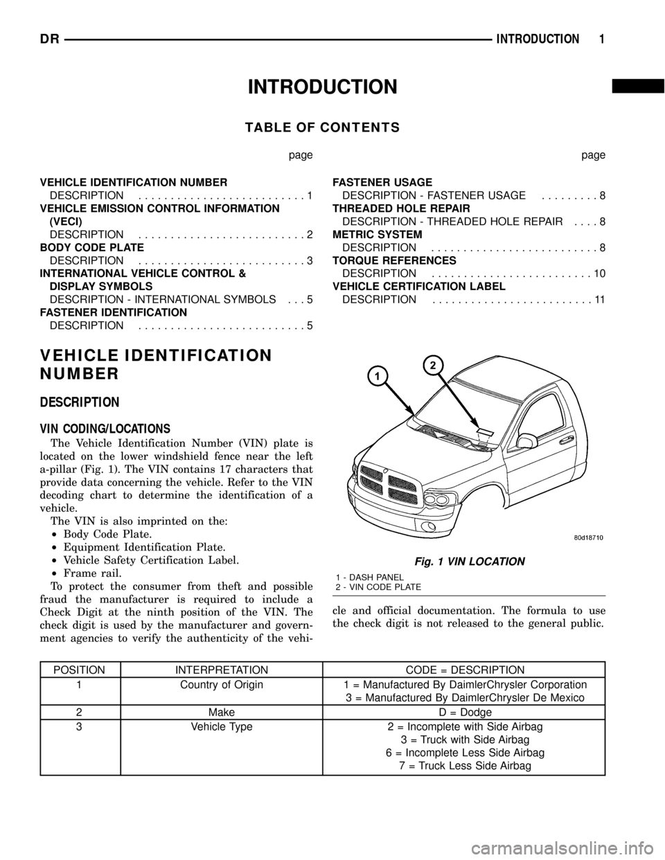
The Vehicle Identification Number (VIN) plate is
located on the lower windshield fence near the left
a-pillar (Fig. 1). The VIN contains 17 characters that
provide data concerning the vehicle. Refer to the VIN
decoding chart to determine the identification of a
vehicle.
The VIN is also imprinted on the:
²Body Code Plate.
²Equipment Identification Plate.
²Vehicle Safety Certification Label.
²Frame rail.
To protect the consumer from theft and possible
fraud the manufacturer is required to include a
Check Digit at the ninth position of the VIN. The
check digit is used by the manufacturer and govern-
ment agencies to verify the authenticity of the vehi-cle and official documentation. The formula to use
the check digit is not released to the general public.
POSITION INTERPRETATION CODE = DESCRIPTION
1 Country of Origin 1 = Manufactured By DaimlerChrysler Corporation
3 = Manufactured By DaimlerChrysler De Mexico
2 Make D = Dodge
3 Vehicle Type 2 = Incomplete with Side Airbag
3 = Truck with Side Airbag
6 = Incomplete Less Side Airbag
7 = Truck Less Side Airbag
Fig. 1 VIN LOCATION
1 - DASH PANEL
2 - VIN CODE PLATE
DRINTRODUCTION 1
Page 3 of 2627

POSITION INTERPRETATION CODE = DESCRIPTION
4 Gross Vehicle Weight Rating G = 5,001-6000 lbs.
H = 6,001-7,000 lbs.
J = 7,001-8,000 lbs.
K = 8,001-9,000 lbs.
L = 9,001-10,000 lbs.
M = 10,001-14,000 lbs.
W = Buses/Incomplete Vehicles with Hydraulic Brakes
5 Vehicle Line A = Ram Pickup 4X2
U = Ram Pickup 4X4
N = Ram Pickup 4X2 DX Family
6 Series 1 = 1500
2 = 2500
3 = 3500 Less Dual Rear Wheels
4 = 3500 With Dual Rear Wheels
5 = 4000 DX Family
7 Body Style 6 = Conventional Cab/Cab Chassis
8 = Quad Cab Full Rear Doors
8 Engine K = 3.7L 6 cyl. MPI Gasoline
N = 4.7L 8 cyl. MPI Gasoline
D = 5.7L 8 cyl. SMPI Gasoline
6 = 5.9L 6 cyl. Turbo Diesel 24v
C = 5.9L 6 cyl. Turbo Diesel High Output
9 Check Digit 0 through 9 or X
10 Model Year 4 = 2004
11 Plant Location S = Dodge City
G = Saltillo
J = St. Louis (North)
12 thru 17 Vehicle Build Sequence
VEHICLE EMISSION CONTROL
INFORMATION (VECI)
DESCRIPTION
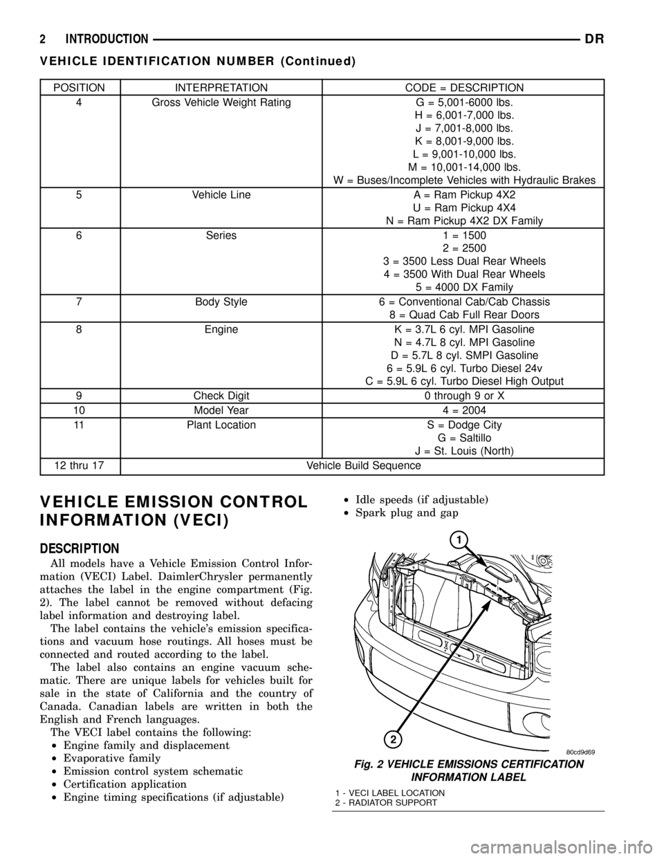
All models have a Vehicle Emission Control Infor-
mation (VECI) Label. DaimlerChrysler permanently
attaches the label in the engine compartment (Fig.
2). The label cannot be removed without defacing
label information and destroying label.
The label contains the vehicle's emission specifica-
tions and vacuum hose routings. All hoses must be
connected and routed according to the label.
The label also contains an engine vacuum sche-
matic. There are unique labels for vehicles built for
sale in the state of California and the country of
Canada. Canadian labels are written in both the
English and French languages.
The VECI label contains the following:
²Engine family and displacement
²Evaporative family
²Emission control system schematic
²Certification application
²Engine timing specifications (if adjustable)²Idle speeds (if adjustable)
²Spark plug and gap
Fig. 2 VEHICLE EMISSIONS CERTIFICATION
INFORMATION LABEL
1 - VECI LABEL LOCATION
2 - RADIATOR SUPPORT
2 INTRODUCTIONDR
VEHICLE IDENTIFICATION NUMBER (Continued)
Page 4 of 2627

BODY CODE PLATE
DESCRIPTION
The Body Code Plate (Fig. 4) is located on the right
front hydroform fender rail just behind the headlight
assembly (Fig. 3). There are seven lines of informa-
tion on the body code plate. Lines 5, 6, and 7 are not
used to define service information. Information reads
from left to right, starting with line 4 in the center of
the plate to line 1 at the bottom of the plate.
The last code imprinted on a vehicle code plate will
be followed by the imprinted word END. When two
vehicle code plates are required, the last available
spaces on the first plate will be imprinted with the
letters CTD (for continued).
When a second vehicle code plate is necessary, the
first four spaces on each row will not be used because
of the plate overlap.
BODY CODE PLATEÐLINE 4
DIGITS 1 THROUGH 12
Vehicle Order Number
DIGITS 13, 14, AND 15
Transmission Codes
²DG4 = 4±speed Automatic (45RFE)
²DG8 = 4±speed Automatic (48RE)²DDC = 5±speed Manual (NV3500)
²DDP = 5±speed Manual (NV4500)
²DEC = 6±speed Manual (NV5600)
²DEE = 6±speed Manual Tremec (T-56)
DIGITS 16, 17, AND 18
Car Line Shell
²DR1=15004X2
²DR6=15004X4
²DR2=25004X2
²DR7=25004X4
²DR3=35004X2
²DR8=35004X4
DIGIT 19
Price Class
²L = Low
²H = Highline
DIGITS 20 AND 21
Body Type
²41 = Ram Truck Quad Cab, Short Box
²42 = Ram Truck Quad Cab, Long Box
²61 = Ram Truck Standard Cab, Short Box
²62 = Ram Truck Standard Cab, Long Box
Fig. 3 BODY CODE PLATE LOCATION
1 - FENDER
2 - RADIATOR CROSSMEMBER
3 - HYDROFORM FENDER RAIL
4 - RIVOT (2)
5 - BODY CODE PLATE
Fig. 4 BODY CODE PLATE
1 - PRIMARY PAINT
2 - SECONDARY PAINT
3 - TRANSMISSION CODE
4 - VEHICLE MODEL NUMBER
5 - ENGINE CODE
6 - INTERIOR TRIM CODE
7 - VEHICLE IDENTIFICATION NUMBER
8 - TAILGATE CODE
9 - CARGO BOX CODE
10 - TAILGATE TRIM CODE
11 - BODY-IN-WHITE SEQUENCE
12 - MARKET CODE
13 - SPECIES CODE
14 - PAINT PROCEDURE
15 - VEHICLE ORDER NUMBER
DRINTRODUCTION 3
Page 5 of 2627

BODY CODE PLATEÐLINE 3
DIGITS 1,2, AND 3
Paint Procedure
²APA = Monotone
²AP9 = Special
²APD = Two-tone (Lower break)
DIGIT 4
Open Space
DIGITS 5 THROUGH 8
Primary Paint
(Refer to 23 - BODY/PAINT - SPECIFICATIONS)
for color codes.
DIGIT 9
Open Space
DIGITS 10 THROUGH 13
Secondary Paint
DIGIT 14
Open Space
DIGITS 15 THROUGH 18
Interior Trim Code
DIGIT 19
Open Space
DIGITS 20, 21, AND 22
Engine Code
²EKG = 3.7 L 6 cyl. MPI Gasoline
²EVA = 4.7 L 8 cyl. MPI Gasoline
²EZA = 5.7 L 8 cyl. SMPI Gasoline
²ETC = 5.9 L 6 cyl. Cummins Turbo Diesel
²ETH = 5.9 L 6 cyl. Cummins Turbo Diesel High
Output
BODY CODE PLATEÐLINE 2
DIGIT 1 Open Space
DIGITS 2 AND 3 Species Code. (Used for Manufacturing)
DIGIT 4
Open Space
DIGIT 5
Market Code
²B = International
²C = Canada
²M = Mexico
²U = United States
DIGIT 6
Open Space
DIGITS 7 THROUGH 23
Vehicle Identification Number (VIN)
(Refer to VEHICLE DATA/VEHICLE INFORMA-
TION/VEHICLE IDENTIFICATION NUMBER -
DESCRIPTION) for proper breakdown of VIN code.
BODY CODE PLATEÐLINE 1
DIGITS 1 THROUGH 6 Body-in-white assembly sequence.
DIGIT 7
Open Space
DIGIT 8 Tailgate trim code.
DIGIT 9
Open Space
DIGITS 10 THROUGH 12 Cargo box code
DIGIT 13
Open Space
DIGITS 14 THROUGH 16 Tailgate code
4 INTRODUCTIONDR
BODY CODE PLATE (Continued)
Page 33 of 2627

CAUTION: Do not crank starter motor on disabled
vehicle for more than 15 seconds, starter will over-
heat and could fail.
(7) Allow battery in disabled vehicle to charge to
at least 12.4 volts (75% charge) before attempting to
start engine. If engine does not start within 15 sec-
onds, stop cranking engine and allow starter to cool
(15 min.), before cranking again.
DISCONNECT CABLE CLAMPS AS FOLLOWS:
²Disconnect BLACK cable clamp from engine
ground on disabled vehicle.
²When using a Booster vehicle, disconnect
BLACK cable clamp from battery negative terminal.
Disconnect RED cable clamp from battery positive
terminal.
²Disconnect RED cable clamp from battery posi-
tive terminal on disabled vehicle.
HOISTING
STANDARD PROCEDURE - HOISTING
Refer to the Owner's Manual for emergency vehicle
lifting procedures.
WARNING: THE HOISTING AND JACK LIFTING
POINTS PROVIDED ARE FOR A COMPLETE VEHI-
CLE. WHEN A CHASSIS OR DRIVETRAIN COMPO-
NENT IS REMOVED FROM A VEHICLE, THE
CENTER OF GRAVITY IS ALTERED MAKING SOME
HOISTING CONDITIONS UNSTABLE. PROPERLY
SUPPORT (Fig. 6) OR SECURE VEHICLE TO HOIST-
ING DEVICE WHEN THESE CONDITIONS EXIST.
FLOOR JACK
When properly positioned, a floor jack can be used
to lift a vehicle (Fig. 7). Support the vehicle in the
raised position with jack stands at the front and rear
ends of the frame rails (Fig. 6).
CAUTION: Do not lift vehicle with a floor jack posi-
tioned under:
²An axle tube.
²A body side sill.
²A steering linkage component.
²A drive shaft.
²The engine or transmission oil pan.
²The fuel tank.
²A front suspension arm.NOTE: Use the correct frame rail lifting locations
only (Fig. 8) and (Fig. 9).
HOIST
A vehicle can be lifted with:
²A single-post, frame-contact hoist.
²A twin-post, chassis hoist.
²A ramp-type, drive-on hoist.
NOTE: When a frame-contact type hoist is used,
verify that the lifting pads are positioned properly
(Fig. 7). The forward lifting pads should be posi-
tioned against the forward flange of the transmis-
sion crossmember brackets at the bottom of the
frame rail (Fig. 8). The real lifting pads should be
wedged between the forward flange of the leaf
spring bracket and the frame rail (Fig. 9). Safety
stands should be placed under the frame rails at
the front and rear ends (Fig. 6).
Fig. 6 Safety Stands
1 - SAFETY STANDS
0 - 20 LUBRICATION & MAINTENANCEDR
JUMP STARTING (Continued)
Page 34 of 2627

TOWING
STANDARD PROCEDURE - TOWING
A vehicle equipped with SAE approved sling-type
towing equipment can be used to tow all vehicles.
When towing a 4WD vehicle using a wheel-lift towing
device, use tow dollies under the opposite end of the
vehicle. A vehicle with flat-bed device can also be
used to transport a disabled vehicle (Fig. 10).
Fig. 7 Vehicle Lifting Locations
Fig. 8 FRONT LIFT PAD LOCATION
1 - BODY MOUNT BRACKET
2 - FRONT LIFT PAD
3 - TRANSMISSION CROSSMEMBER BRACKET
4 - FRAME RAIL
Fig. 9 REAR LIFT PAD LOCATION
1 - FRAME RAIL
2 - REAR LIFT PAD
3 - LEAF SPRING MOUNTING BRACKET
4 - BOX MOUNTING BRACKET
Fig. 10 Tow Vehicles With Approved Equipment
1 - SLING TYPE
2 - WHEEL LIFT
3 - FLAT BED
DRLUBRICATION & MAINTENANCE 0 - 21
TOWING (Continued)
Page 79 of 2627

(3) Tighten the upper and lower bolt/nuts Tighten
to 135 N.m (100 ft. lbs.)
(4) Remove the support and lower the vehicle.
SPRING
DESCRIPTION
The rear suspension system uses a multi-leaf
springs and a solid drive axle. The forward end of the
springs are mounted to the body rail hangers
through rubber bushings. The rearward end of the
springs are attached to the body by the use of shack-
les. The spring and shackles use rubber bushings.
OPERATION
The springs control ride quality and maintain vehi-
cle ride height. The shackles allow the springs to
change their length as the vehicle moves over various
road conditions.
REMOVAL
(1) Raise and support the vehicle.
(2) Support the axle with a suitable holding fix-
ture.
(3) Remove the nuts, spring clamp bolts and the
plate that attach the spring to the axle (Fig. 4).
(4) Remove the nuts and bolts from the spring
front and rear shackle (Fig. 4).
(5) Remove the spring from the vehicle.
INSTALLATION
(1) Position spring on axle shaft tube so spring
center bolt is inserted into the locating hole in the
axle tube.(2) Align the front of the spring with the bolt hole
in the front bracket. Install the eye pivot bolt and
nut.
(3) Align the rear of the spring into the shackle
and install the bolt and nut.
(4) Tighten the spring front and rear eye pivot bolt
snug do not torque.
(5) Install the spring clamp bolts, plate and the
retaining nuts.
(6) Remove the holding fixture for the rear axle.
(7) Remove the supports and lower the vehicle so
that the weight is being supported by the tires.
(8) Tighten the spring clamp retaining nuts to 149
N´m (110 ft. lbs.).
(9) Tighten the spring front and rear pivot bolt
nuts to 163 N´m (120 ft. lbs.)(LD) or 230 N´m (170 ft.
lbs.)(HD).
SPRING TIP INSERTS
REMOVAL
(1) Raise and support the vehicle.
(2) Remove both rear tireand wheel assemblies
(3) Position a large C-Clamp adjacent to the spring
clinch clip and clamp the leaves of the spring
together
Fig. 3 SHOCK ABSORBER
1 - NUT
2 - AXLE
3 - SHOCK ABSORBER
Fig. 4 REAR SPRING
1 - LEAF SPRING
2 - PLATE
3 - NUTS
4 - FRONT NUT & BOLT
5 - SPRING CLAMP BOLTS
6 - SHACKLES
2 - 44 REARDR
SHOCK (Continued)
Page 130 of 2627

PINION GEAR/RING GEAR
REMOVAL
NOTE: The ring gear and pinion are serviced in a
matched set. Never replace one without replacing
the other.
(1) Remove differential from housing.
(2) Place differential case in a vise with soft jaw
(Fig. 44).
(3) Remove bolts holding ring gear to differential
case.
(4) Drive ring gear from differential case with a
soft hammer (Fig. 44).
(5) Mark companion yoke and companion flange
for installation reference.
(6) Remove companion flange bolts and tie the pro-
peller shaft to the vehicle underbody.
(7) Rotate companion flange three or four times
and verify flange rotates smoothly.
(8) Record pinion rotating torque an inch pound
torque wrench for installation reference (Fig. 45).
(9) Install bolts into two of the threaded holes in
the companion flange 180É apart.
(10) Position Holder 6719 against the companion
flange and install a bolt and washer into one of the
remaining threaded holes. Tighten the bolts so that
the Holder 6719 is held to the flange.(11) Remove the pinion nut.
(12) Remove the companion flange with Remover
C-452 (Fig. 46).
(13) Remove pinion from differential housing.
(14) Remove pinion seal with a pry tool or a slide
hammer mounted screw.
(15) Remove oil slinger, if equipped and front pin-
ion bearing.
(16) Remove front pinion bearing cup with
Remover 8831 and Handle C-4171 (Fig. 47).
Fig. 43 DIFFERENTIAL CASE BEARINGS
1 - HANDLE
2 - DIFFERENTIAL
3 - BEARING
4 - INSTALLER
Fig. 44 RING GEAR
1 - DIFFERENTIAL CASE
2 - RING GEAR
3 - HAMMER
Fig. 45 PINION ROTATING TORQUE
1 - PINION COMPANION FLANGE
2 - TORQUE WRENCH
DRFRONT AXLE - C205F 3 - 49
DIFFERENTIAL CASE BEARINGS (Continued)
Page 187 of 2627

INSTALLATION
(1) Install differential side bearings (3) with
Installer C-4213 (4) and Handle C-4171 (1) (Fig. 53).
(2) Install differential case into housing.
PINION GEAR/RING GEAR/
TONE RING
REMOVAL
NOTE: The ring gear and pinion are serviced in a
matched set. Never replace one gear without replac-
ing the other matching gear.
(1) Mark companion flange and propeller shaft for
installation reference.
(2) Disconnect propeller shaft from the companion
flange and tie propeller shaft to underbody.
(3) Remove axle shafts.
(4) Remove differential from the differential hous-
ing.
(5) Place differential case in a vise with soft metal
jaw protectors..
(6) Remove ring gear bolts from the differential
case.
(7) Drive ring gear off the differential case with a
rawhide hammer (Fig. 54).(8) Install bolts into two of the threaded holes in
the companion flange 180É apart.
(9) Position Holder 6719 against the companion
flange and install a bolt and washer into one of the
remaining threaded holes. Tighten the bolts so the
Holder 6719 is held to the flange.
(10) Use Holder 6719 to hold companion flange
and remove the companion flange nut and washer.
(11) Remove companion flange with Remover
C-452 (Fig. 55).
Fig. 53 DIFFERENTIAL CASE BEARING
1 - HANDLE
2 - DIFFERENTIAL
3 - BEARING
4 - INSTALLER
Fig. 54 RING GEAR
1 - CASE
2 - RING GEAR
3 - RAWHIDE HAMMER
Fig. 55 COMPANION FLANGE
1 - COMPANION FLANGE
2 - REMOVER
3 - 106 REAR AXLE-91/4DR
DIFFERENTIAL CASE BEARINGS (Continued)