Engine torque spec DODGE RAM 1500 1998 2.G Workshop Manual
[x] Cancel search | Manufacturer: DODGE, Model Year: 1998, Model line: RAM 1500, Model: DODGE RAM 1500 1998 2.GPages: 2627
Page 40 of 2627
angle while adjusting caster, move one pivot bolt of
the upper control arm in or out. Then move the other
pivot bolt of the upper control arm in the opposite
direction. Install special tool 8876 between the top of
the upper control arm bracket and the upper control
arm (on 1500 series 4X2 & 4X4). Install special tool
8876 between the bottom of the upper control arm
bracket pressing the tool against the frame and the
upper control arm (on 2500/3500 series 4X2) in order
to move the upper control arm outwards for proper
adjustment with the vehicle at normal ride height
(Fig. 3).
To increase positive caster angle, move the rear
position of the upper control arm inward (toward the
engine). Move the front of the upper control arm out-
ward (away from the engine) slightly until the origi-
nal camber angle is obtained using special tool 8876
to move the upper control arm for proper adjustment.
(Fig. 3)
CAMBER
Move both pivot bolts of the upper control arm
together in or out. This will change the camber angle
significantly and little effect on the caster angle
using special tool 8876 to move the upper control
arm for proper adjustment. (Fig. 3)
After adjustment is made tighten the upper control
arm nuts to proper torque specification.
TOE ADJUSTMENT
The wheel toe position adjustment is the final
adjustment.
(1) Start the engine and turn wheels both ways
before straightening the wheels. Secure the steering
wheel with the front wheels in the straight-ahead
position.
(2) Loosen the tie rod jam nuts.
NOTE: Each front wheel should be adjusted for
one-half of the total toe position specification. This
will ensure the steering wheel will be centered
when the wheels are positioned straight-ahead.
(3) Adjust the wheel toe position by turning the
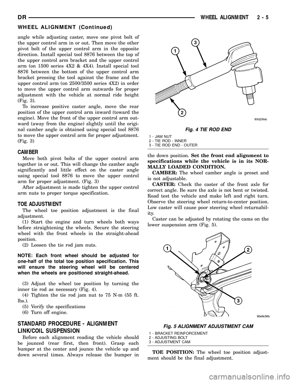
inner tie rod as necessary (Fig. 4).
(4) Tighten the tie rod jam nut to 75 N´m (55 ft.
lbs.).
(5) Verify the specifications
(6) Turn off engine.
STANDARD PROCEDURE - ALIGNMENT
LINK/COIL SUSPENSION
Before each alignment reading the vehicle should
be jounced (rear first, then front). Grasp each
bumper at the center and jounce the vehicle up and
down several times. Always release the bumper inthe down position.Set the front end alignment to
specifications while the vehicle is in its NOR-
MALLY LOADED CONDITION.
CAMBER:The wheel camber angle is preset and
is not adjustable.
CASTER:Check the caster of the front axle for
correct angle. Be sure the axle is not bent or twisted.
Road test the vehicle and make left and right turn.
Observe the steering wheel return-to-center position.
Low caster will cause poor steering wheel returnabil-
ity.
Caster can be adjusted by rotating the cams on the
lower suspension arm (Fig. 5).
TOE POSITION:The wheel toe position adjust-
ment should be the final adjustment.
Fig. 4 TIE ROD END
1 - JAM NUT
2 - TIE ROD - INNER
3 - TIE ROD END - OUTER
Fig. 5 ALIGNMENT ADJUSTMENT CAM
1 - BRACKET REINFORCEMENT
2 - ADJUSTING BOLT
3 - ADJUSTMENT CAM
DRWHEEL ALIGNMENT 2 - 5
WHEEL ALIGNMENT (Continued)
Page 83 of 2627
DRIVELINE VIBRATION
Drive Condition Possible Cause Correction
Propeller Shaft Noise 1) Undercoating or other foreign
material on shaft.1) Clean exterior of shaft and wash
with solvent.
2) Loose U-joint clamp screws. 2) Install new clamps and screws
and tighten to proper torque.
3) Loose or bent U-joint yoke or
excessive runout.3) Install new yoke.
4) Incorrect driveline angularity. 4) Measure and correct driveline
angles.
5) Rear spring center bolt not in
seat.5) Loosen spring u-bolts and seat
center bolt.
6) Worn U-joint bearings. 6) Install new U-joint.
7) Propeller shaft damaged or out
of balance.7) Installl new propeller shaft.
8) Broken rear spring. 8) Install new rear spring.
9) Excessive runout or unbalanced
condition.9) Re-index propeller shaft, test,
and evaluate.
10) Excessive drive pinion gear
shaft runout.10) Re-index propeller shaft and
evaluate.
11) Excessive axle yoke deflection. 11) Inspect and replace yoke if
necessary.
12) Excessive transfer case runout. 12) Inspect and repair as necessary.
Universal Joint Noise 1) Loose U-joint clamp screws. 1) Install new clamps and screws
and tighten to proper torque.
2) Lack of lubrication. 2) Replace as U-joints as
necessary.
PROPELLER SHAFT BALANCE
If propeller shaft is suspected of being out of bal-
ance, use the following procedure.
NOTE: Indexing propeller shaft 180É relative to the
yoke may eliminate some vibrations.
(1) Raise and support vehicle.
(2) Clean all foreign material from the propeller
shaft and universal joints.
(3) Inspect propeller shaft for missing balance
weights, broken welds and bent areas.If propeller
shaft is bent, it must be replaced.
(4) Inspect universal joints for wear and properly
installed.
(5) Check propeller shaft bolt torques.
(6) Remove wheels and install lug nuts to retain
brake rotors.
(7) Mark and number the shaft six inches from the
pinion yoke end at four positions 90É apart.
(8) Run and accelerate vehicle until vibration
occurs. Note the intensity and speed the vibration
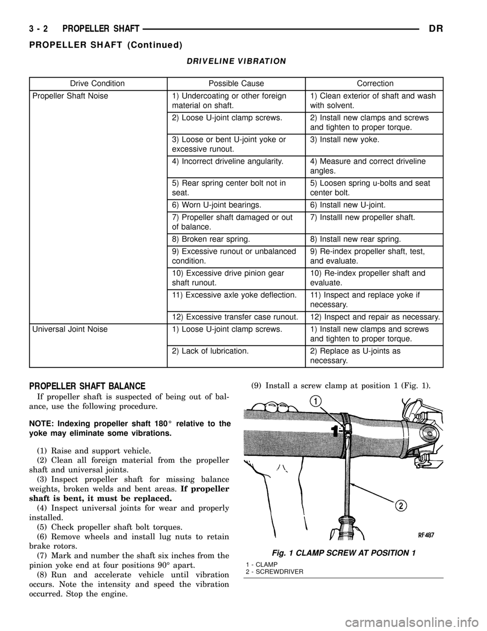
occurred. Stop the engine.(9) Install a screw clamp at position 1 (Fig. 1).
Fig. 1 CLAMP SCREW AT POSITION 1
1 - CLAMP
2 - SCREWDRIVER
3 - 2 PROPELLER SHAFTDR
PROPELLER SHAFT (Continued)
Page 178 of 2627
(10) If rotating torque is low, use Holder 6719 to
hold the companion flange and tighten pinion nut in
6.8 N´m (5 ft. lbs.) increments until proper rotating
torque is achieved.
NOTE: The bearing rotating torque should be con-
stant during a complete revolution of the pinion. If
the rotating torque varies, this indicates a binding
condition.
NOTE: The seal replacement is unacceptable if the
final pinion nut torque is less than 285 N´m (210 ft.
lbs.).
(11) Install propeller shaft with the installation
reference marks aligned.
(12) Tighten the companion flange bolts to 108
N´m (80 ft. lbs.).
(13) Install brake rotors.
(14) Check the differential lubricant level.
DIFFERENTIAL COVER
REMOVAL
(1) With vehicle in neutral, position vehicle on
hoist.
(2) Remove drain plug.
(3) Remove cover bolts.
(4) Remove cover and drain lubricant.
INSTALLATION
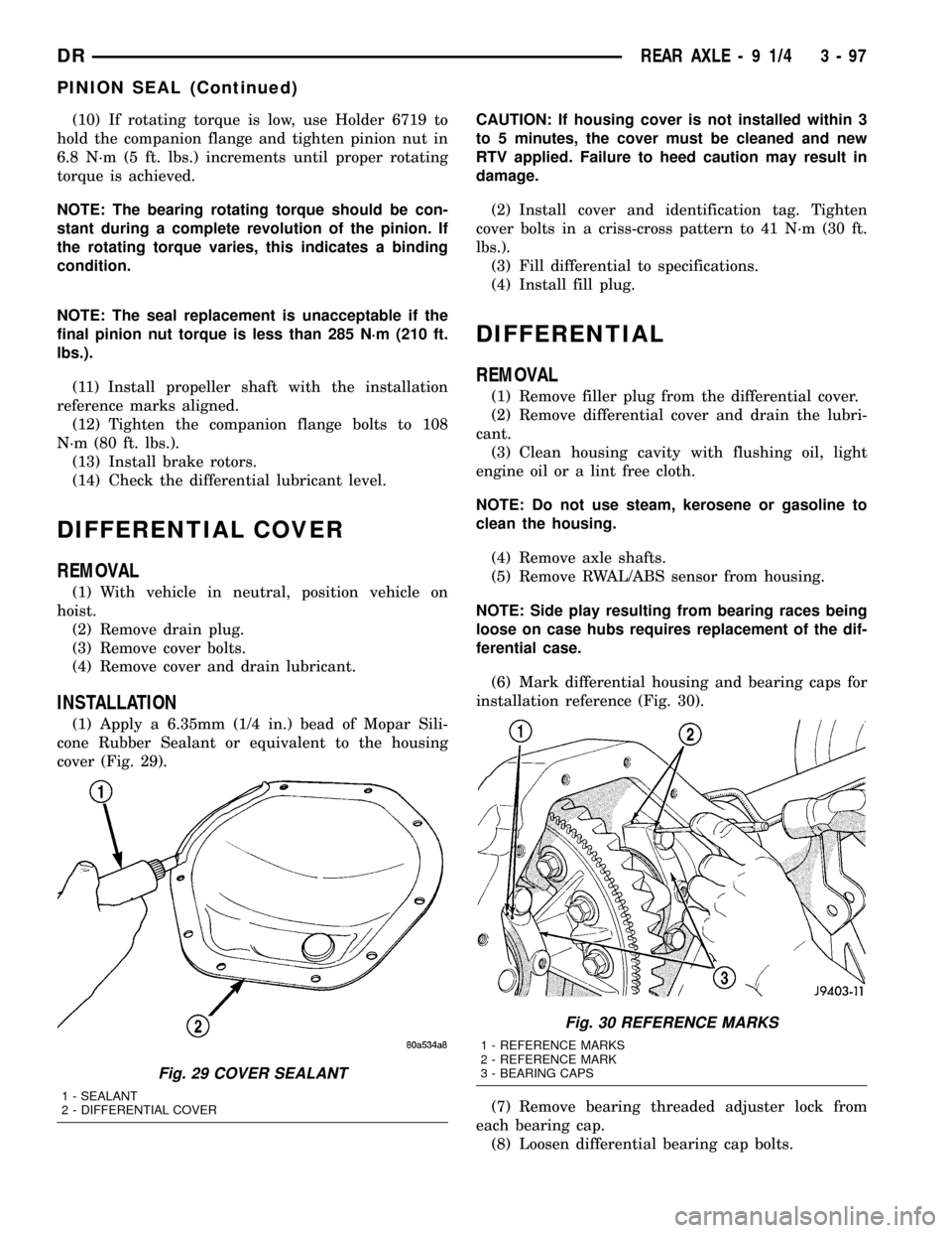
(1) Apply a 6.35mm (1/4 in.) bead of Mopar Sili-
cone Rubber Sealant or equivalent to the housing
cover (Fig. 29).CAUTION: If housing cover is not installed within 3
to 5 minutes, the cover must be cleaned and new
RTV applied. Failure to heed caution may result in
damage.
(2) Install cover and identification tag. Tighten
cover bolts in a criss-cross pattern to 41 N´m (30 ft.
lbs.).
(3) Fill differential to specifications.
(4) Install fill plug.
DIFFERENTIAL
REMOVAL
(1) Remove filler plug from the differential cover.
(2) Remove differential cover and drain the lubri-
cant.
(3) Clean housing cavity with flushing oil, light
engine oil or a lint free cloth.
NOTE: Do not use steam, kerosene or gasoline to
clean the housing.
(4) Remove axle shafts.
(5) Remove RWAL/ABS sensor from housing.
NOTE: Side play resulting from bearing races being
loose on case hubs requires replacement of the dif-
ferential case.
(6) Mark differential housing and bearing caps for
installation reference (Fig. 30).
(7) Remove bearing threaded adjuster lock from
each bearing cap.
(8) Loosen differential bearing cap bolts.
Fig. 29 COVER SEALANT
1 - SEALANT
2 - DIFFERENTIAL COVER
Fig. 30 REFERENCE MARKS
1 - REFERENCE MARKS
2 - REFERENCE MARK
3 - BEARING CAPS
DRREAR AXLE - 9 1/4 3 - 97
PINION SEAL (Continued)
Page 182 of 2627
DIFFERENTIAL TEST
The differential can be tested without removing the
differential case by measuring rotating torque. Make
sure brakes are not dragging during this measure-
ment.
(1) Place blocks in front and rear of both front
wheels.
(2) Raise one rear wheel until it is completely off
the ground.
(3) Engine off, transmission in neutral, and park-
ing brake off.
(4) Remove wheel and bolt Special Tool 6790 or
equivalent tool to studs.
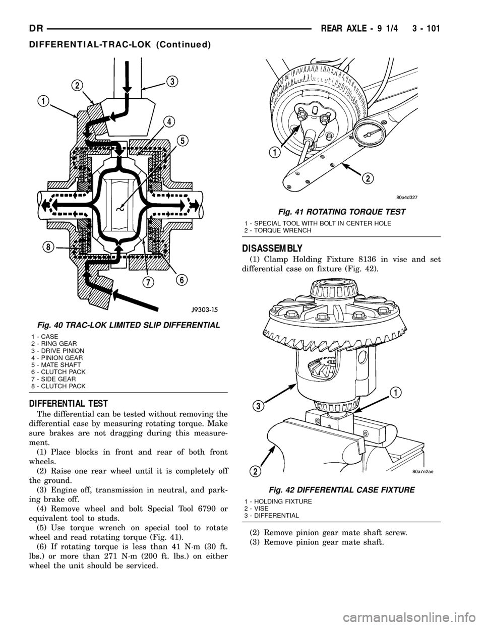
(5) Use torque wrench on special tool to rotate
wheel and read rotating torque (Fig. 41).
(6) If rotating torque is less than 41 N´m (30 ft.
lbs.) or more than 271 N´m (200 ft. lbs.) on either
wheel the unit should be serviced.
DISASSEMBLY
(1) Clamp Holding Fixture 8136 in vise and set
differential case on fixture (Fig. 42).
(2) Remove pinion gear mate shaft screw.
(3) Remove pinion gear mate shaft.
Fig. 40 TRAC-LOK LIMITED SLIP DIFFERENTIAL
1 - CASE
2 - RING GEAR
3 - DRIVE PINION
4 - PINION GEAR
5 - MATE SHAFT
6 - CLUTCH PACK
7 - SIDE GEAR
8 - CLUTCH PACK
Fig. 41 ROTATING TORQUE TEST
1 - SPECIAL TOOL WITH BOLT IN CENTER HOLE
2 - TORQUE WRENCH
Fig. 42 DIFFERENTIAL CASE FIXTURE
1 - HOLDING FIXTURE
2 - VISE
3 - DIFFERENTIAL
DRREAR AXLE - 9 1/4 3 - 101
DIFFERENTIAL-TRAC-LOK (Continued)
Page 306 of 2627
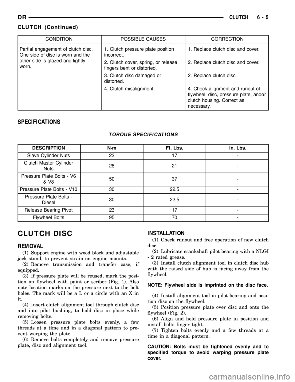
CONDITION POSSIBLE CAUSES CORRECTION
Partial engagement of clutch disc.
One side of disc is worn and the
other side is glazed and lightly
worn.1. Clutch pressure plate position
incorrect.1. Replace clutch disc and cover.
2. Clutch cover, spring, or release
fingers bent or distorted.2. Replace clutch disc and cover.
3. Clutch disc damaged or
distorted.2. Replace clutch disc.
4. Clutch misalignment. 4. Check alignment and runout of
flywheel, disc, pressure plate, andùr
clutch housing. Correct as
necessary.
SPECIFICATIONS
TORQUE SPECIFICATIONS
DESCRIPTION N´m Ft. Lbs. In. Lbs.
Slave Cylinder Nuts 23 17 -
Clutch Master Cylinder
Nuts28 21 -
Pressure Plate Bolts - V6
&V850 37 -
Pressure Plate Bolts - V10 30 22.5 -
Pressure Plate Bolts -
Diesel30 22.5 -
Release Bearing Pivot 23 17 -
Flywheel Bolts 95 70 -
CLUTCH DISC
REMOVAL
(1) Support engine with wood block and adjustable
jack stand, to prevent strain on engine mounts.
(2) Remove transmission and transfer case, if
equipped.
(3) If pressure plate will be reused, mark the posi-
tion on flywheel with paint or scriber (Fig. 1). Also
note location marks on the pressure next to the bolt
holes. The mark will be a L or a circle with an X in
it.
(4) Insert clutch alignment tool through clutch disc
and into pilot bushing, to hold disc in place while
removing bolts.
(5) Loosen pressure plate bolts evenly, a few
threads at a time and in a diagonal pattern to pre-
vent warping the plate.
(6) Remove bolts completely and remove pressure
plate, disc and alignment tool.
INSTALLATION
(1) Check runout and free operation of new clutch
disc.
(2) Lubricate crankshaft pilot bearing with a NLGI
- 2 rated grease.
(3) Install clutch alignment tool in clutch disc hub
with the raised side of hub is facing away from the
flywheel.
NOTE: Flywheel side is imprinted on the disc face.
(4) Install alignment tool in pilot bearing and posi-
tion disc on the flywheel.
(5) Position pressure plate over disc and onto the
flywheel (Fig. 2).
(6) Align and hold pressure plate in position and
install bolts finger tight.
(7) Tighten bolts evenly and a few threads at a
time in a diagonal pattern.
CAUTION: Bolts must be tightened evenly and to
specified torque to avoid warping pressure plate
cover.
DRCLUTCH 6 - 5
CLUTCH (Continued)
Page 312 of 2627
Common causes of runout are:
²heat warpage
²improper machining
²incorrect bolt tightening
²improper seating on crankshaft flange shoulder
²foreign material on crankshaft flange
Flywheel machining is not recommended. The fly-
wheel clutch surface is machined to a unique contour
and machining will negate this feature. Minor fly-
wheel scoring can be cleaned up by hand with 180
grit emery or with surface grinding equipment.
Remove only enough material to reduce scoring
(approximately 0.001 - 0.003 in.). Heavy stock
removal isnot recommended.Replace the flywheel
if scoring is severe and deeper than 0.076 mm (0.003
in.). Excessive stock removal can result in flywheel
cracking or warpage after installation; it can also
weaken the flywheel and interfere with proper clutch
release.
Clean the crankshaft flange before mounting the
flywheel. Dirt and grease on the flange surface may
cock the flywheel causing excessive runout. Use new
bolts when remounting a flywheel and secure the
bolts with Mopar Lock And Seal or equivalent.
Tighten flywheel bolts to specified torque only. Over-
tightening can distort the flywheel hub causing
runout.
REMOVAL
(1) Remove transmission.
(2) Remove pressure plate and clutch.
(3) Remove flywheel bolts and remove flywheel.
DISASSEMBLY
NOTE: If the teeth are worn or damaged, the fly-
wheel should be replaced as an assembly. This is
the recommended repair. In cases where a new fly-
wheel is not readily available, (V10/Diesel Engine
only) a replacement ring gear can be installed. The
following procedure must be observed to avoid
damaging the flywheel and replacement gear.
WARNING: WEAR PROTECTIVE GOGGLES OR
SAFETY GLASSES WHILE CUTTING RING GEAR.
(1) Mark position of the old gear for alignment ref-
erence on the flywheel. Use a scriber for this pur-
pose.
(2) Remove the old gear by cutting most of the way
through it (at one point) with an abrasive cut-off
wheel. Then complete removal with a cold chisel or
punch.
ASSEMBLY
NOTE: The ring gear is a shrink fit on the flywheel.
This means the gear must be expanded by heating
in order to install it. The method of heating and
expanding the gear is extremely important. Every
surface of the gear must be heated at the same
time to produce uniform expansion. An oven or
similar enclosed heating device must be used. Tem-
perature required for uniform expansion is approxi-
mately 375É F.
CAUTION: Do not use an oxy/acetylene torch to
remove the old gear, or to heat and expand a new
gear. The high temperature of the torch flame can
cause localized heating that will damage the fly-
wheel. In addition, using the torch to heat a replace-
ment gear will cause uneven heating and
expansion. The torch flame can also anneal the
gear teeth resulting in rapid wear and damage after
installation.
WARNING: WEAR PROTECTIVE GOGGLES OR
SAFETY GLASSES AND HEAT RESISTENT GLOVES
WHEN HANDLING A HEATED RING GEAR.
(1) The heated gear must be installed evenly to
avoid misalignment or distortion.
(2)
Position and install the heated ring gear on the
flywheel with a shop press and a suitable press plates.
(3) Place flywheel on work bench and let it cool in
normal shop air. Allow the ring gear to cool down
completely before installation it on the engine.
CAUTION: Do not use water or compressed air to
cool the flywheel. The rapid cooling produced by
water or compressed air will distort or crack the
new gear.
INSTALLATION
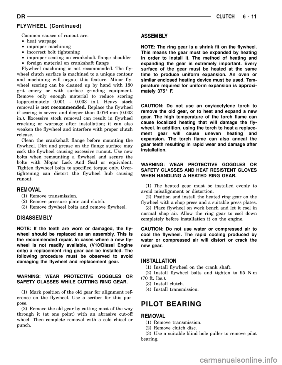
(1) Install flywheel on the crank shaft.
(2) Install flywheel bolts and tighten to 95 N´m
(70 ft. lbs.).
(3) Install clutch.
(4) Install transmission.
PILOT BEARING
REMOVAL
(1) Remove transmission.
(2) Remove clutch disc.
(3) Use a suitable blind hole puller to remove pilot
bearing.
DRCLUTCH 6 - 11
FLYWHEEL (Continued)
Page 316 of 2627
COOLING
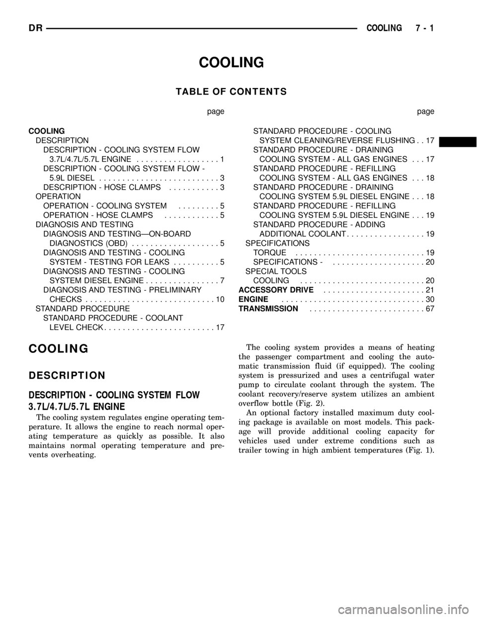
TABLE OF CONTENTS
page page
COOLING
DESCRIPTION
DESCRIPTION - COOLING SYSTEM FLOW
3.7L/4.7L/5.7L ENGINE..................1
DESCRIPTION - COOLING SYSTEM FLOW -
5.9L DIESEL..........................3
DESCRIPTION - HOSE CLAMPS...........3
OPERATION
OPERATION - COOLING SYSTEM.........5
OPERATION - HOSE CLAMPS............5
DIAGNOSIS AND TESTING
DIAGNOSIS AND TESTINGÐON-BOARD
DIAGNOSTICS (OBD)...................5
DIAGNOSIS AND TESTING - COOLING
SYSTEM - TESTING FOR LEAKS..........5
DIAGNOSIS AND TESTING - COOLING
SYSTEM DIESEL ENGINE................7
DIAGNOSIS AND TESTING - PRELIMINARY
CHECKS............................10
STANDARD PROCEDURE
STANDARD PROCEDURE - COOLANT
LEVEL CHECK........................17STANDARD PROCEDURE - COOLING
SYSTEM CLEANING/REVERSE FLUSHING . . 17
STANDARD PROCEDURE - DRAINING
COOLING SYSTEM - ALL GAS ENGINES . . . 17
STANDARD PROCEDURE - REFILLING
COOLING SYSTEM - ALL GAS ENGINES . . . 18
STANDARD PROCEDURE - DRAINING
COOLING SYSTEM 5.9L DIESEL ENGINE . . . 18
STANDARD PROCEDURE - REFILLING
COOLING SYSTEM 5.9L DIESEL ENGINE . . . 19
STANDARD PROCEDURE - ADDING
ADDITIONAL COOLANT.................19
SPECIFICATIONS
TORQUE............................19
SPECIFICATIONS -....................20
SPECIAL TOOLS
COOLING...........................20
ACCESSORY DRIVE......................21
ENGINE...............................30
TRANSMISSION.........................67
COOLING
DESCRIPTION
DESCRIPTION - COOLING SYSTEM FLOW
3.7L/4.7L/5.7L ENGINE
The cooling system regulates engine operating tem-
perature. It allows the engine to reach normal oper-
ating temperature as quickly as possible. It also
maintains normal operating temperature and pre-
vents overheating.The cooling system provides a means of heating
the passenger compartment and cooling the auto-
matic transmission fluid (if equipped). The cooling
system is pressurized and uses a centrifugal water
pump to circulate coolant through the system. The
coolant recovery/reserve system utilizes an ambient
overflow bottle (Fig. 2).
An optional factory installed maximum duty cool-
ing package is available on most models. This pack-
age will provide additional cooling capacity for
vehicles used under extreme conditions such as
trailer towing in high ambient temperatures (Fig. 1).
DRCOOLING 7 - 1
Page 334 of 2627
STANDARD PROCEDURE - REFILLING
COOLING SYSTEM 5.9L DIESEL ENGINE
Clean cooling system prior to refilling (Refer to 7 -
COOLING - STANDARD PROCEDURE).
(1) Close radiator drain plug.
CAUTION: Due to the use of the one-way check
valve, the engine must not be operating when refill-
ing the cooling system.
NOTE: The diesel engine is equipped with two one-
way check valves (jiggle pins). The check valves
are used as a servicing feature and will vent air
when the system is being filled. Water pressure (or
flow) will hold the valves closed.
(2) Fill the cooling system with a 50/50 mixture of
water and antifreeze.
(3) Fill coolant reserve/overflow tank to the FULL
mark.
(4) Start and operate engine until thermostat
opens. Upper radiator hose should be warm to touch.
(5) If necessary, add 50/50 water and antifreeze
mixture to the coolant reserve/overflow tank to main-
tain coolant level. This level should be between the
ADD and FULL marks. The level in the reserve/over-
flow tank may drop below the ADD mark after three
or four warm-up and cool-down cycles.
STANDARD PROCEDURE - ADDING
ADDITIONAL COOLANT
The use of aluminum cylinder blocks, cylinder
heads and water pumps requires special corrosion
protection. Only MopartAntifreeze/Coolant, 5
Year/100,000 Mile Formula (glycol base coolant with
corrosion inhibitors called HOAT, for Hybrid Organic
Additive Technology) is recommended. This coolant
offers the best engine cooling without corrosion when
mixed with 50% distilled water to obtain a freeze
point of -37ÉC (-35ÉF). If it loses color or becomes con-
taminated, drain, flush, and replace with fresh prop-
erly mixed coolant solution.
CAUTION: Do not use coolant additives that are
claimed to improve engine cooling.
Do not remove the radiator cap to add coolant to
the system. When adding coolant to maintain the cor-
rect level, do so only at the reserve/overflow bottle.
Remove the radiator cap only for testing or when
refilling the system after service. Removing the cap
unnecessarily can cause loss of coolant and allow air
to enter the system, which produces corrosion.
WARNING: DO NOT REMOVE OR LOOSEN THE
RADIATOR CAP WITH THE COOLING SYSTEM HOTAND UNDER PRESSURE. SERIOUS BURNS FROM
THE COOLANT OR HIGH PRESSURE STEAM CAN
OCCUR.
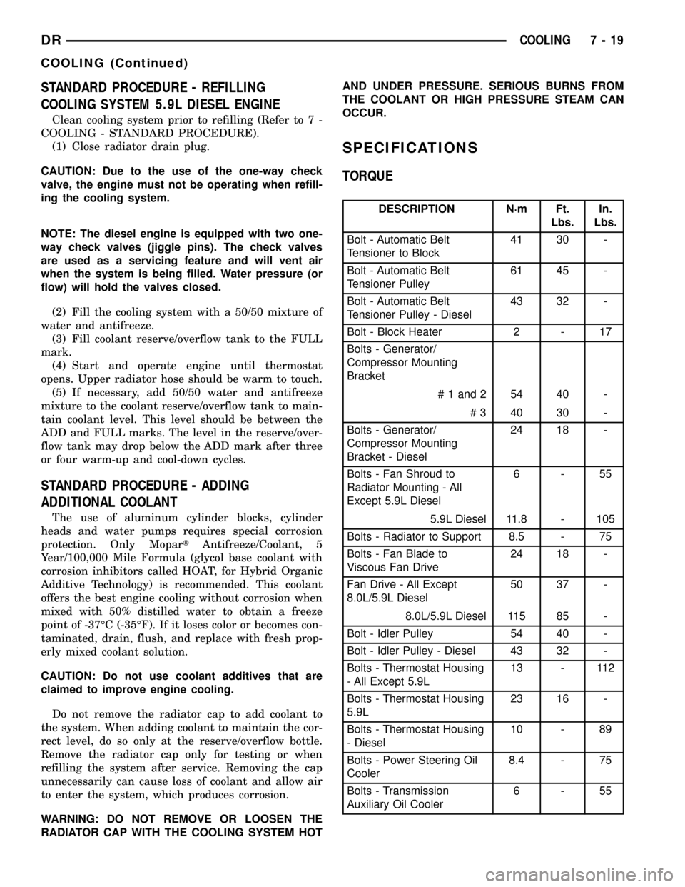
SPECIFICATIONS
TORQUE
DESCRIPTION N´m Ft.
Lbs.In.
Lbs.
Bolt - Automatic Belt
Tensioner to Block41 30 -
Bolt - Automatic Belt
Tensioner Pulley61 45 -
Bolt - Automatic Belt
Tensioner Pulley - Diesel43 32 -
Bolt - Block Heater 2 - 17
Bolts - Generator/
Compressor Mounting
Bracket
# 1 and 2 54 40 -
# 3 40 30 -
Bolts - Generator/
Compressor Mounting
Bracket - Diesel24 18 -
Bolts - Fan Shroud to
Radiator Mounting - All
Except 5.9L Diesel6-55
5.9L Diesel 11.8 - 105
Bolts - Radiator to Support 8.5 - 75
Bolts - Fan Blade to
Viscous Fan Drive24 18 -
Fan Drive - All Except
8.0L/5.9L Diesel50 37 -
8.0L/5.9L Diesel 115 85 -
Bolt - Idler Pulley 54 40 -
Bolt - Idler Pulley - Diesel 43 32 -
Bolts - Thermostat Housing
- All Except 5.9L13 - 112
Bolts - Thermostat Housing
5.9L23 16 -
Bolts - Thermostat Housing
- Diesel10 - 89
Bolts - Power Steering Oil
Cooler8.4 - 75
Bolts - Transmission
Auxiliary Oil Cooler6-55
DRCOOLING 7 - 19
COOLING (Continued)
Page 337 of 2627
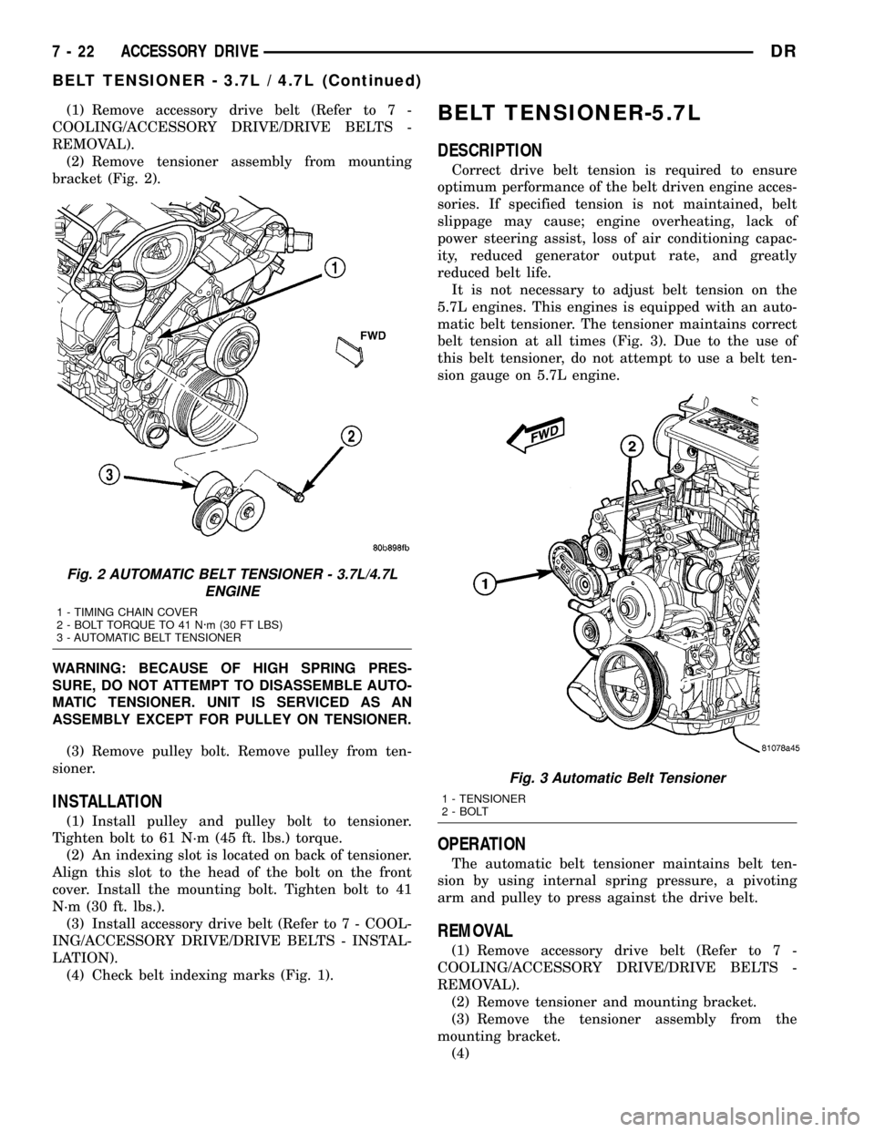
(1) Remove accessory drive belt (Refer to 7 -
COOLING/ACCESSORY DRIVE/DRIVE BELTS -
REMOVAL).
(2) Remove tensioner assembly from mounting
bracket (Fig. 2).
WARNING: BECAUSE OF HIGH SPRING PRES-
SURE, DO NOT ATTEMPT TO DISASSEMBLE AUTO-
MATIC TENSIONER. UNIT IS SERVICED AS AN
ASSEMBLY EXCEPT FOR PULLEY ON TENSIONER.
(3) Remove pulley bolt. Remove pulley from ten-
sioner.
INSTALLATION
(1) Install pulley and pulley bolt to tensioner.
Tighten bolt to 61 N´m (45 ft. lbs.) torque.
(2) An indexing slot is located on back of tensioner.
Align this slot to the head of the bolt on the front
cover. Install the mounting bolt. Tighten bolt to 41
N´m (30 ft. lbs.).
(3) Install accessory drive belt (Refer to 7 - COOL-
ING/ACCESSORY DRIVE/DRIVE BELTS - INSTAL-
LATION).
(4) Check belt indexing marks (Fig. 1).
BELT TENSIONER-5.7L
DESCRIPTION
Correct drive belt tension is required to ensure
optimum performance of the belt driven engine acces-
sories. If specified tension is not maintained, belt
slippage may cause; engine overheating, lack of
power steering assist, loss of air conditioning capac-
ity, reduced generator output rate, and greatly
reduced belt life.
It is not necessary to adjust belt tension on the
5.7L engines. This engines is equipped with an auto-
matic belt tensioner. The tensioner maintains correct
belt tension at all times (Fig. 3). Due to the use of
this belt tensioner, do not attempt to use a belt ten-
sion gauge on 5.7L engine.
OPERATION
The automatic belt tensioner maintains belt ten-
sion by using internal spring pressure, a pivoting
arm and pulley to press against the drive belt.
REMOVAL
(1) Remove accessory drive belt (Refer to 7 -
COOLING/ACCESSORY DRIVE/DRIVE BELTS -
REMOVAL).
(2) Remove tensioner and mounting bracket.
(3) Remove the tensioner assembly from the
mounting bracket.
(4)
Fig. 2 AUTOMATIC BELT TENSIONER - 3.7L/4.7L
ENGINE
1 - TIMING CHAIN COVER
2 - BOLT TORQUE TO 41 N´m (30 FT LBS)
3 - AUTOMATIC BELT TENSIONER
Fig. 3 Automatic Belt Tensioner
1 - TENSIONER
2 - BOLT
7 - 22 ACCESSORY DRIVEDR
BELT TENSIONER - 3.7L / 4.7L (Continued)
Page 349 of 2627
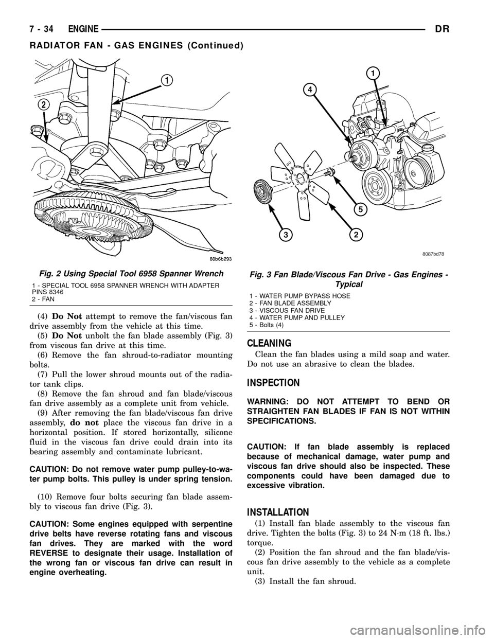
(4)Do Notattempt to remove the fan/viscous fan
drive assembly from the vehicle at this time.
(5)Do Notunbolt the fan blade assembly (Fig. 3)
from viscous fan drive at this time.
(6) Remove the fan shroud-to-radiator mounting
bolts.
(7) Pull the lower shroud mounts out of the radia-
tor tank clips.
(8) Remove the fan shroud and fan blade/viscous
fan drive assembly as a complete unit from vehicle.
(9) After removing the fan blade/viscous fan drive
assembly,do notplace the viscous fan drive in a
horizontal position. If stored horizontally, silicone
fluid in the viscous fan drive could drain into its
bearing assembly and contaminate lubricant.
CAUTION: Do not remove water pump pulley-to-wa-
ter pump bolts. This pulley is under spring tension.
(10) Remove four bolts securing fan blade assem-
bly to viscous fan drive (Fig. 3).
CAUTION: Some engines equipped with serpentine
drive belts have reverse rotating fans and viscous
fan drives. They are marked with the word
REVERSE to designate their usage. Installation of
the wrong fan or viscous fan drive can result in
engine overheating.
CLEANING
Clean the fan blades using a mild soap and water.
Do not use an abrasive to clean the blades.
INSPECTION
WARNING: DO NOT ATTEMPT TO BEND OR
STRAIGHTEN FAN BLADES IF FAN IS NOT WITHIN
SPECIFICATIONS.
CAUTION: If fan blade assembly is replaced
because of mechanical damage, water pump and
viscous fan drive should also be inspected. These
components could have been damaged due to
excessive vibration.
INSTALLATION
(1) Install fan blade assembly to the viscous fan
drive. Tighten the bolts (Fig. 3) to 24 N´m (18 ft. lbs.)
torque.
(2) Position the fan shroud and the fan blade/vis-
cous fan drive assembly to the vehicle as a complete
unit.
(3) Install the fan shroud.
Fig. 2 Using Special Tool 6958 Spanner Wrench
1 - SPECIAL TOOL 6958 SPANNER WRENCH WITH ADAPTER
PINS 8346
2-FAN
Fig. 3 Fan Blade/Viscous Fan Drive - Gas Engines -
Typical
1 - WATER PUMP BYPASS HOSE
2 - FAN BLADE ASSEMBLY
3 - VISCOUS FAN DRIVE
4 - WATER PUMP AND PULLEY
5 - Bolts (4)
7 - 34 ENGINEDR
RADIATOR FAN - GAS ENGINES (Continued)