headlamp DODGE RAM 2001 Service Repair Manual
[x] Cancel search | Manufacturer: DODGE, Model Year: 2001, Model line: RAM, Model: DODGE RAM 2001Pages: 2889, PDF Size: 68.07 MB
Page 2678 of 2889
hook formations on the lower edge of the glove box
door are engaged with and pivot on three hinge pins
integral to the lower edge of the instrument panel
support structure. The glove box door also serves as
the passenger side knee blocker. A honeycomb struc-
ture between the inner and outer glove box door pan-
els helps to absorb the impact load and distribute it
to the instrument panel structure.
²Steering Column Opening Cover- The steer-
ing column opening cover serves as the driver side
knee blocker. This molded plastic cover has an inte-
gral ribbed plastic liner concealed behind it, for
increased strength and integrity. The steering column
opening cover transfers impact loads to the instru-
ment panel structural support.
²Top Cover- The instrument panel top cover or
base trim is the molded, grained, and color impreg-
nated plastic outer skin of the instrument panel
structural support.
Hard wired circuitry connects the electrical compo-
nents on the instrument panel to each other through
the electrical system of the vehicle. These hard wired
circuits are integral to several wire harnesses, which
are routed throughout the vehicle and retained by
many different methods. These circuits may be con-
nected to each other, to the vehicle electrical system
and to the instrument panel components through the
use of a combination of soldered splices, splice block
connectors and many different types of wire harness
terminal connectors and insulators. Refer to the
appropriate wiring information. The wiring informa-
tion includes complete circuit diagrams, proper wire
and connector repair procedures, further details on
wire harness routing and retention, as well as pin-
out and location views for the various wire harness
connectors, splices, and grounds.
OPERATION
The instrument panel serves as the command cen-
ter of the vehicle, which necessarily makes it a very
complex unit. The instrument panel is designed to
house the controls and monitors for standard and
optional powertrains, climate control systems, audio
systems, safety systems, and many other comfort or
convenience items. When the components of the
instrument panel structural support are properly
assembled and secured in the vehicle they provide
superior instrument panel stiffness and integrity to
help reduce buzzes, squeaks, and rattles. This type of
construction also provides improved energy absorp-
tion which, in conjunction with the dual airbags and
seat belts, helps to improve occupant protection.
The instrument panel is also designed so that all of
the various controls can be safely reached and the
monitors can be easily viewed by the vehicle operator
when driving, while still allowing relative ease ofaccess to each of these items for service. Modular
instrument panel construction allows all of the
gauges and controls to be serviced from the front of
the panel. In addition, most of the instrument panel
electrical components can be accessed without com-
plete instrument panel removal. However, if neces-
sary, the instrument panel can be removed from the
vehicle as an assembly.
The steering column opening cover with its inte-
gral knee blocker located on the driver side of the
instrument panel works in conjunction with the air-
bag system in a frontal vehicle impact to keep the
driver properly positioned for an airbag deployment.
In addition, removal of this component provides
access to the steering column mounts, the steering
column wiring, the Junction Block (JB) (removal of a
snap-fit fuse access panel on the left end of the
instrument panel allows access to the fuses and cir-
cuit breakers), the Central Timer Module (CTM), the
Infinity speaker filter choke and relay unit, much of
the instrument panel wiring, and the gear selector
indicator cable (automatic transmission).
In a frontal collision, the glove box door on the pas-
senger side of the instrument panel provides the
same function for the front seat passenger as the
knee blocker does for the driver. The glove box door
also incorporates a recessed latch handle. Removal of
the glove box provides access to the passenger airbag,
the glove box lamp and switch, the radio antenna
coaxial cable, the heating and air conditioning vac-
uum harness connector, and additional instrument
panel wiring.
Removal of the instrument panel cluster bezel
allows access to the headlamp switch, instrument
cluster, radio, passenger airbag on-off switch, heated
seat switches (if equipped), and the heating and air
conditioning control. Removal of the instrument clus-
ter allows access to the cluster illumination and indi-
cator bulbs, and more of the instrument panel
wiring. Complete instrument panel removal is
required for service of most components internal to
the heating and air conditioning system housing,
including the heater core and the evaporator.
See the owner's manual in the vehicle glove box for
more information on the features, use and operation
of all of the components and systems mounted on or
in the instrument panel.
BR/BEINSTRUMENT PANEL SYSTEM 23 - 105
INSTRUMENT PANEL SYSTEM (Continued)
Page 2679 of 2889
REMOVAL
WARNING: ON VEHICLES EQUIPPED WITH AIR-
BAGS, DISABLE THE AIRBAG SYSTEM BEFORE
ATTEMPTING ANY STEERING WHEEL, STEERING
COLUMN, OR INSTRUMENT PANEL COMPONENT
DIAGNOSIS OR SERVICE. DISCONNECT AND ISO-
LATE THE BATTERY NEGATIVE (GROUND) CABLE,
THEN WAIT TWO MINUTES FOR THE AIRBAG SYS-
TEM CAPACITOR TO DISCHARGE BEFORE PER-
FORMING FURTHER DIAGNOSIS OR SERVICE. THIS
IS THE ONLY SURE WAY TO DISABLE THE AIRBAG
SYSTEM. FAILURE TO TAKE THE PROPER PRE-
CAUTIONS COULD RESULT IN ACCIDENTAL AIR-
BAG DEPLOYMENT AND POSSIBLE PERSONAL
INJURY.
NOTE: Before starting this procedure, be certain to
turn the steering wheel until the front wheels are in
the straight-ahead position.
(1) Disconnect and isolate the battery negative
cable.
(2) Remove the Airbag Control Module (ACM) and
bracket from the floor panel transmission tunnel.
(Refer to 8 - ELECTRICAL/RESTRAINTS/AIRBAG
CONTROL MODULE - REMOVAL).
(3) Remove the trim from the left and right cowl
side inner panels. (Refer to 23 - BODY/INTERIOR/
COWL TRIM COVER - REMOVAL).
(4) Remove the steering column opening cover
from the instrument panel. (Refer to 23 - BODY/IN-
STRUMENT PANEL/STEERING COLUMN OPEN-
ING COVER - REMOVAL).
(5) Remove the two screws that secure the inside
hood latch release handle to the instrument panel
lower reinforcement and lower the release handle to
the floor.
(6) Disconnect the clockspring pigtail wire connec-
tor from the instrument panel wire harness connec-
tor located on the instrument panel lower
reinforcement.
(7) If the vehicle is so equipped, disconnect the
overdrive lockout switch pigtail wire connector from
the instrument panel wire harness connector near
the instrument panel lower reinforcement.
(8) Remove the steering column from the vehicle,
but do not remove the driver airbag, the steering
wheel, or the switches from the column. Be certain
that the steering wheel is locked and secured from
rotation to prevent the loss of clockspring centering.
(Refer to 19 - STEERING/COLUMN - REMOVAL).
(9) From under the driver side of the instrument
panel, perform the following:
(a) Disengage the park brake release handle
linkage rod from the park brake mechanism on theleft cowl side inner panel. (Refer to 5 - BRAKES/
PARKING BRAKE/RELEASE - REMOVAL).
(b) Disconnect the instrument panel wire har-
ness connector from the park brake switch on the
park brake mechanism.
(c) Disconnect the three connectors (one from the
body wire harness, and two from the headlamp and
dash wire harness) from the three connector recep-
tacles located closest to the dash panel on the back
of the Junction Block (JB).
(d) Remove the screw from the center of the
headlamp and dash wire harness to instrument
panel wire harness bulkhead connector and discon-
nect the connector.
(e) Disconnect the instrument panel wire har-
ness to door wire harness connector located directly
below the instrument panel wire harness to head-
lamp and dash wire harness bulkhead connector.
(f) If the vehicle is equipped with the Infinity
sound system option, disconnect the Infinity wire
harness connector from the instrument panel wire
harness connector that is secured to the outboard
side of the instrument panel wire harness to head-
lamp and dash wire harness bulkhead connector.
(g) Disconnect the instrument panel wire har-
ness connector from the stop lamp switch.
(h) Disconnect the heater-A/C housing vacuum
harness connector from the heater-A/C control vac-
uum harness connector located near the left end of
the heater-A/C housing.
(10) From under the passenger side of the instru-
ment panel, disconnect the two halves of the radio
antenna coaxial cable connector.
(11) Loosen the right and left instrument panel
cowl side roll-down bracket screws about 13 mm
(0.50 inch) (Fig. 1).
(12) Remove the five screws that secure the top of
the instrument panel to the top of the dash panel,
removing the center screw last.
(13) Roll down the instrument panel and install a
temporary hook in the center hole on top of the
instrument panel. Secure the other end of the hook
to the center hole in the top of the dash panel. The
hook should support the instrument panel in its
rolled down position about 46 cm (18 inches) from
the dash panel.
(14) With the instrument panel supported in the
roll-down position, disconnect the instrument panel
wire harness connectors from the heater-A/C housing
wire harness connectors.
(15) With the aid of an assistant, remove the tem-
porary hook and lift the instrument panel assembly
off of the roll-down bracket screws and remove it
from the vehicle.
23 - 106 INSTRUMENT PANEL SYSTEMBR/BE
INSTRUMENT PANEL SYSTEM (Continued)
Page 2681 of 2889
cowl side inner panel. (Refer to 5 - BRAKES/PARK-
ING BRAKE/RELEASE - INSTALLATION).
(b) Reconnect the instrument panel wire harness
connector to the park brake switch on the park
brake mechanism.
(c) Reconnect the three connectors (one from the
body wire harness, and two from the headlamp and
dash wire harness) to the three connector recepta-
cles located closest to the dash panel on the back of
the Junction Block (JB).
(d) Reconnect the headlamp and dash wire har-
ness to instrument panel wire harness bulkhead
connector and tighten the screw in the center of
the connector. Tighten the screw to 3.5 N´m (31 in.
lbs.).
(e) Reconnect the instrument panel wire harness
to door wire harness connector located directly
below the instrument panel wire harness to head-
lamp and dash wire harness bulkhead connector.
(f) If the vehicle is equipped with the Infinity
sound system option, reconnect the Infinity wire
harness connector to the instrument panel wire
harness connector that is secured to the outboard
side of the instrument panel wire harness to head-
lamp and dash wire harness bulkhead connector.
(g) Reconnect the instrument panel wire harness
connector to the stop lamp switch.
(h) Reconnect the heater-A/C housing vacuum
harness connector to the heater-A/C control vac-
uum harness connector located near the left end of
the heater-A/C housing.
(8) Reinstall the steering column into the vehicle.
Be certain that the steering wheel was locked and
secured from rotation to prevent the loss of clock-
spring centering. (Refer to 19 - STEERING/COL-
UMN - INSTALLATION).
(9) If the vehicle is so equipped, reconnect the
overdrive lockout switch pigtail wire connector to the
instrument panel wire harness connector near the
instrument panel lower reinforcement.
(10) Reconnect the clockspring pigtail wire connec-
tor to the instrument panel wire harness connector
at the instrument panel lower reinforcement.
(11) Position the inside hood latch release handle
to the instrument panel lower reinforcement.
(12) Install and tighten the two screws that secure
the inside hood latch release handle to the instru-
ment panel lower reinforcement. Tighten the screws
to 2.8 N´m (25 in. lbs.).
(13) Reinstall the steering column opening cover
onto the instrument panel. (Refer to 23 - BODY/IN-
STRUMENT PANEL/STEERING COLUMN OPEN-
ING COVER - INSTALLATION).
(14) Reinstall the trim onto the left and right cowl
side inner panels. (Refer to 23 - BODY/INTERIOR/
COWL TRIM COVER - INSTALLATION).(15) Reinstall the Airbag Control Module (ACM)
and bracket onto the floor panel transmission tunnel.
(Refer to 8 - ELECTRICAL/RESTRAINTS/AIRBAG
CONTROL MODULE - INSTALLATION).
(16) Reconnect the battery negative cable.
ASH RECEIVER
REMOVAL
WARNING: ON VEHICLES EQUIPPED WITH AIR-
BAGS, DISABLE THE AIRBAG SYSTEM BEFORE
ATTEMPTING ANY STEERING WHEEL, STEERING
COLUMN, OR INSTRUMENT PANEL COMPONENT
DIAGNOSIS OR SERVICE. DISCONNECT AND ISO-
LATE THE BATTERY NEGATIVE (GROUND) CABLE,
THEN WAIT TWO MINUTES FOR THE AIRBAG SYS-
TEM CAPACITOR TO DISCHARGE BEFORE PER-
FORMING FURTHER DIAGNOSIS OR SERVICE. THIS
IS THE ONLY SURE WAY TO DISABLE THE AIRBAG
SYSTEM. FAILURE TO TAKE THE PROPER PRE-
CAUTIONS COULD RESULT IN ACCIDENTAL AIR-
BAG DEPLOYMENT AND POSSIBLE PERSONAL
INJURY.
(1) Disconnect and isolate the battery negative
cable.
(2) Open the instrument panel ash receiver.
(3) From the open position, close the ash receiver
slightly and pull it straight back far enough to disen-
gage it from the pivot pins in the lower instrument
panel.
(4) Remove the three screws that secure the ash
receiver flame shield to the lower instrument panel
(Fig. 2).
(5) Pull the ash receiver flame shield out from the
instrument panel far enough to disengage the two
retaining tabs on the top of the shield from the
mounting holes in the instrument panel.
(6) Lower the flame shield from the instrument
panel far enough to access the ash receiver lamp and
hood.
(7) Squeeze the ash receiver lamp and hood
bracket to disengage the unit from the mounting hole
in the flame shield.
(8) Remove the ash receiver flame shield from the
instrument panel.
23 - 108 INSTRUMENT PANEL SYSTEMBR/BE
INSTRUMENT PANEL SYSTEM (Continued)
Page 2837 of 2889
BODY INTERIOR
INSPECTION - COMPASS
NOTE: Set variance after calibration.
(1) Calibrate and set compass variance (Fig. 26), if
so equipped (use appropriate procedures in service
information).
(2) Remove protective film from overhead console,
if equipped.
INSPECTION - FIT AND FINISH
(1) Remove any interior covers.
(2) Inspect the instrument panel, glove box door
(Fig. 27) and interior moldings for even gaps and
alignments.
(3) Check that the door panel material is clean,
free from wrinkles and installed correctly.
(4) Check that the seat material is clean, secure
and free of wrinkles.
(5) Check that the carpet is clean, secure and free
of wrinkles.
(6) Check that the headliner is clean, free of lint
and dirt smudges.
INSPECTION - LIGHTS AND SWITCHES
(1) Remove protective film from all switch bezels.
(2) Operate and visually inspect all interior lights
and switches, including:
²Dome/map lamps
²Vanity mirror lamps
²Glove box light²Ashtray light
²Cigar lighter light
²All gauge lights
²Radio display
²Door-mounted lights, if equipped
²Illuminated entry system, if equipped
(3) Visually inspect and operate all exterior lights
and their switches, including:
NOTE: Headlamp aim is preset during vehicle
assembly.
²Headlights, including high beam, optical horn
(ªflash to passº) and daylight running lamps (DRL's)
(Fig. 28)
²Tail/stop lamps (including center high-mounted
stop lamp)
²Parking lights Turn signals Brake lights (includ-
ing center high mounted stop lamp)
²Emergency flashers (Fig. 29)
²Fog/driving lights, if equipped
²Off-road or other lights, if equipped
²Cargo bed lights, if equipped
(4) Check ignition switch for proper operation in
all positions (accessory, lock, on, start and off).
INSPECTION - SEAT BELTS, SHOULDER
BELTS, RETRACTORS AND HEAD RESTRAINTS
(1) Inspect all seat belts and harnesses to ensure
that they connect and hold properly.
(2) Inspect the condition of the belts and anchors.
(3) Inspect for proper seat belt retraction.
Fig. 26 COMPASS OPERATION
Fig. 27 GLOVE BOX DOOR
30 - 12 NEW VEHICLE PREPARATIONBR/BE
Page 2838 of 2889
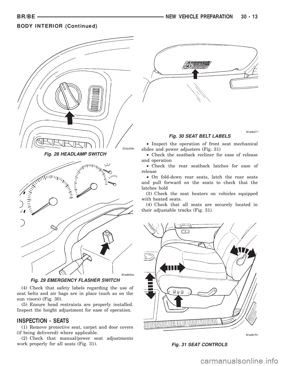
(4) Check that safety labels regarding the use of
seat belts and air bags are in place (such as on the
sun visors) (Fig. 30).
(5) Ensure head restraints are properly installed.
Inspect the height adjustment for ease of operation.
INSPECTION - SEATS
(1) Remove protective seat, carpet and door covers
(if being delivered) where applicable.
(2) Check that manual/power seat adjustments
work properly for all seats (Fig. 31).²Inspect the operation of front seat mechanical
slides and power adjusters (Fig. 31)
²Check the seatback recliner for ease of release
and operation
²Check the rear seatback latches for ease of
release
²On fold-down rear seats, latch the rear seats
and pull forward on the seats to check that the
latches hold
(3) Check the seat heaters on vehicles equipped
with heated seats.
(4) Check that all seats are securely located in
their adjustable tracks (Fig. 31).
Fig. 31 SEAT CONTROLS
Fig. 28 HEADLAMP SWITCH
Fig. 29 EMERGENCY FLASHER SWITCH
Fig. 30 SEAT BELT LABELS
BR/BENEW VEHICLE PREPARATION 30 - 13
BODY INTERIOR (Continued)
Page 2845 of 2889
STANDARD PROCEDURE - PRE DELIVERY
STORAGE
(1) If possible, store vehicles indoors, in clean, dry
places. If vehicles must be stored outdoors:
²Try to avoid storage locations that are near any
obvious sources of industrial or environmental con-
tamination (e.g., trees, factories, steam or vapor
vents, railroad tracks, etc.)
²Maintain tight security to help prevent pilferage
and vandalism, and inspect each vehicle regularly to
check for such damage
²If the vehicle must be parked on an incline, park
it with the front end higher than the rear; this will
prevent ªhydrostatic lockº caused by fuel draining
into the engine
²Rinse the vehicle at least once a week. Snow
should be washed away more often, since it can trap
harmful contaminants. Dry all horizontal surfaces
(2) The IOD fuse should be removed in order to
prevent battery drain and possible damage.
(3) Check the vehicle's coolant and anti-freeze pro-
tection.
(4) Check the vehicle's battery at least once a
month for a proper charge (at least 12.4 volts).
Charge the battery if necessary. This will help pre-
vent freezing and deterioration.
(5) Check the vehicle's tires and inflate them to
their maximum recommended levels. Move the vehi-
cles periodically to avoid ªflatspottingº the tires.
(6) Do not engage the parking brake; keep it in the
OFF position.
(7) Keep all windows closed, all doors locked, and
all trim covers intact and in place.
(8) Do not use chalks, crayons or any marker con-
taining abrasives on painted, plated or glass sur-
faces.
(9) Always use seat covers when moving a vehicle.
PROGRAMMABLE
ELECTRONIC FEATURES
DESCRIPTION
The programming of electronic features applies to
specific DaimlerChrysler Corporation vehicles. Not
all vehicles are equipped with these electronic fea-
tures, and not all vehicles equipped with electronic
features have all the available features. Programma-
ble electronic features are subject to change and may
be added or deleted from specific vehicle models.
(1) The programmable electronic features that may
be provided on the vehicle are:
²Rolling Power Door Locks
²Horn Chirp (When Doors Locked With Remote
Keyless Entry)²Headlamp Flash (When Doors Locked or
Unlocked With Remote Keyless Entry)
²Low Fuel Chime
²Remote Keyless Entry Door Unlock Sequence
²Headlights On Automatically With Wipers
²Turn Signal Chime
²12V Power Outlet
²Remote Unlock
²Remote Linked To Memory
²Headlamp Delay
²Service Interval
²Easy Exit Seat
(2) Programming any of the above features is to be
performed prior to vehicle delivery to the customer,
depending on customer preference.
NOTE: For all vehicles except Caravan/Town and
Country, the programming must be performed using
the DRB IIITscan tool. On Caravan/Town and Coun-
try vehicles the features can be programmed using
the DRB IIITscan tool or by button pushing
sequences. The customer can perform program-
ming, if desired, by following the instructions out-
lined in the owner manual.
OPERATION
NOTE: The programmable features provided on
vehicles need to be explained to the customer at
the time of sale. The customer's preferences con-
cerning the features should be noted and pro-
grammed accordingly during predelivery.
NOTE: When using the DRB IIITscan tool to enable/
disable any programmable electronic features, go to
the main menu item #9 on the DRB IIITscan tool.
This is ªCustomer Preferencesº. You must choose
ªCustomer Preferencesº on the main menu to pro-
gram the desired features.
ROLLING POWER DOOR LOCKS
With this feature enabled, the vehicle's door lock-
ing mechanisms automatically lock when the vehicle
reaches approximately 24 Km/h (15 mph).
HORN CHIRP
NOTE: This feature can be enabled with or without
the headlamp flash feature.
The horn chirp function is a feature that can be
enabled or disabled on vehicles equipped with
30 - 20 NEW VEHICLE PREPARATIONBR/BE
PRE DELIVERY STORAGE (Continued)
Page 2846 of 2889
Remote Keyless Entry (RKE). The horn chirps when
the vehicle is locked with the RKE transmitter.
HEADLAMP FLASH
NOTE: This feature can be enabled with or without
the horn chirp feature.
The headlamp flash function is a feature that can
be enabled or disabled on vehicles equipped with
Remote Keyless Entry (RKE). The headlamps flash
once when the vehicle is locked with the RKE trans-
mitter, and flash twice when the vehicle is unlocked
with the RKE transmitter.
LOW FUEL CHIME
All vehicles equipped with the audible low fuel
chime are shipped with this feature enabled.
REMOTE KEYLESS ENTRY (RKE) DOOR UNLOCK
SEQUENCE
Two door unlock sequences are provided on vehi-
cles equipped with this feature. When using the RKE
transmitter to unlock the doors, pressing the unlock
button once when the feature is enabled unlocks only
the driver's door. Pushing the RKE transmitter
unlock button a second time unlocks the remaining
doors. When the RKE door unlock feature is disabled,
all doors unlock with one press of the RKE transmit-
ter unlock button.
HEADLIGHTS ON AUTOMATICALLY WITH WIPERS
This feature appears on vehicles that have, as an
option, automatic headlights. When the windshield
wipers are turned on, the headlights automatically
turn on.
12V POWER OUTLET
This feature currently appears on Caravan/Voyag-
er/Town and Country vehicles. The vehicles are
shipped with the 12V power outlets turned off with
the ignition key. The relay can be changed to make
the outlets powered at all times. This feature may be
of interest to customers with cell phones.
TURN SIGNAL CHIME
This feature is an audible turn signal warning
chime. The chime sounds if the turn signal is on, the
vehicle has traveled one mile and vehicle speed has
exceeded 40 Km/h (25 mph).
REMOTE UNLOCK
The remote unlock function is a feature that can be
enabled or disabled on vehicles equipped with
Remote Keyless Entry (RKE). With the first press of
the RKE transmitter to unlock the doors, the driver's
door only unlocks. With the second press of the RKEtransmitter, the remaining doors and the liftgate
unlock. With the remote unlock feature enabled, the
first press of the RKE transmitter unlocks all doors.
REMOTE LINKED TO MEMORY
The remote linked to memory function is currently
only available only on Jeep Grand Cherokee Limited
vehicles. When enabled, this feature recalls a mem-
ory of seats, mirror and radio presets and positions
when unlocking the vehicle with the RKE transmit-
ter.
HEADLAMP DELAY
Currently available only on Jeep Grand Cherokee
vehicles, the headlamp delay timeout can be set to
30, 60 or 90 seconds. This timeout only occurs when
the ignition is turned off prior to turning the head-
lamps off, or when leaving the headlamps in AUTO
mode.
SERVICE INTERVAL
Currently available only on Jeep Grand Cherokee
vehicles, the interval for the service reminder mes-
sage can be set from 3,219 kilometers to 12,070 kilo-
meters (2,000 miles to 7,500 miles).
EASY EXIT SEAT
Currently available only on Jeep Grand Cherokee
Limited vehicles, the driver's seat will reposition
55mm (2.1 inches) rearward, or the end of travel if
less than 55mm (2.1 inches) and full downward when
the key is removed from the ignition. This feature
allows ease of exiting the vehicle. The seat will repo-
sition itself to the memory location when the vehicle
is unlocked using the RKE transmitter or by pressing
the memory buttons on the door panel.
APPEARANCE TIPS
CLEANING
(1) Before delivering the new vehicle to the cus-
tomer, the following checks on appearance details are
recommended:
²Wash the vehicle to remove all traces of road
grime and other dirt on the car from new vehicle
preparation operations
²Clean the tire sidewalls
²Clean exterior and interior glass surfaces
²Remove all protective covers
²Remove undercoat overspray, excess window
sealer, and excess weatherstrip adhesive
²Inspect interior trim, seats, carpeting, and mold-
ings. Clean as necessary
²Remove shipping and inspection stickers
BR/BENEW VEHICLE PREPARATION 30 - 21
PROGRAMMABLE ELECTRONIC FEATURES (Continued)
Page 2848 of 2889
ABS INDICATOR - DESCRIPTION.........8J-14
ABS INDICATOR - OPERATION..........8J-14
A/C APPLICATION TABLE,
SPECIFICATIONS......................24-8
A/C COMPRESSOR - DESCRIPTION......24-46
A/C COMPRESSOR - DIAGNOSIS AND
TESTING...........................24-46
A/C COMPRESSOR - INSTALLATION......24-47
A/C COMPRESSOR - OPERATION........24-46
A/C COMPRESSOR - REMOVAL.........24-47
A/C COMPRESSOR CLUTCH -
DESCRIPTION.......................24-13
A/C COMPRESSOR CLUTCH -
INSPECTION........................24-16
A/C COMPRESSOR CLUTCH -
INSTALLATION.......................24-16
A/C COMPRESSOR CLUTCH -
OPERATION.........................24-13
A/C COMPRESSOR CLUTCH - REMOVAL . . 24-14
A/C COMPRESSOR CLUTCH BREAK-IN -
STANDARD PROCEDURE...............24-13
A/C COMPRESSOR CLUTCH COIL -
DIAGNOSIS AND TESTING.............24-13
A/C COMPRESSOR CLUTCH RELAY -
DESCRIPTION.......................24-17
A/C COMPRESSOR CLUTCH RELAY -
DIAGNOSIS AND TESTING.............24-17
A/C COMPRESSOR CLUTCH RELAY -
INSTALLATION.......................24-18
A/C COMPRESSOR CLUTCH RELAY -
OPERATION.........................24-17
A/C COMPRESSOR CLUTCH RELAY -
REMOVAL..........................24-18
A/C CONDENSER - DESCRIPTION........24-48
A/C CONDENSER - INSTALLATION.......24-49
A/C CONDENSER - OPERATION..........24-48
A/C CONDENSER - REMOVAL...........24-49
A/C EVAPORATOR - DESCRIPTION.......24-52
A/C EVAPORATOR - INSTALLATION......24-53
A/C EVAPORATOR - OPERATION.........24-53
A/C EVAPORATOR - REMOVAL..........24-53
A/C HEATER CONTROL - DESCRIPTION . . . 24-18
A/C HEATER CONTROL - DIAGNOSIS
AND TESTING.......................24-19
A/C HEATER CONTROL - INSTALLATION . . . 24-20
A/C HEATER CONTROL - OPERATION.....24-18
A/C HEATER CONTROL - REMOVAL......24-19
A/C HIGH PRESSURE SWITCH -
DESCRIPTION.......................24-20
A/C HIGH PRESSURE SWITCH -
DIAGNOSIS AND TESTING.............24-20
A/C HIGH PRESSURE SWITCH -
INSTALLATION.......................24-21
A/C HIGH PRESSURE SWITCH -
OPERATION.........................24-20
A/C HIGH PRESSURE SWITCH -
REMOVAL..........................24-21
A/C LINE COUPLERS - DESCRIPTION.....24-40
A/C LINE COUPLERS - OPERATION......24-41
A/C LINE COUPLERS - STANDARD
PROCEDURE........................24-43
A/C LOW PRESSURE SWITCH -
DESCRIPTION.......................24-21
A/C LOW PRESSURE SWITCH -
DIAGNOSIS AND TESTING.............24-21
A/C LOW PRESSURE SWITCH -
INSTALLATION.......................24-22
A/C LOW PRESSURE SWITCH -
OPERATION.........................24-21
A/C LOW PRESSURE SWITCH -
REMOVAL..........................24-21
A/C ORIFICE TUBE - DESCRIPTION.......24-53
A/C ORIFICE TUBE - OPERATION........24-53
A/C ORIFICE TUBE - REMOVAL..........24-54
A/C PERFORMANCE - DIAGNOSIS AND
TESTING............................24-2
ACCELERATOR PEDAL - INSTALLATION . . . 14-37
ACCELERATOR PEDAL - REMOVAL.......14-37
ACCELERATOR PEDAL POSITION
SENSOR - DESCRIPTION
...............14-91
ACCELERATOR PEDAL POSITION
SENSOR - INSTALLATION
..............14-93
ACCELERATOR PEDAL POSITION
SENSOR - OPERATION
................14-91
ACCELERATOR PEDAL POSITION
SENSOR - REMOVAL
..................14-91
ACCESSORY DRIVE BELT - DIAGNOSIS
AND TESTING
................7-24,7-27,7-31ACCUMULATOR - DESCRIPTION.........24-54
ACCUMULATOR - DESCRIPTION . 21-191,21-362,
21-537,21-707
ACCUMULATOR - INSPECTION . . 21-192,21-363,
21-538,21-708
ACCUMULATOR - INSTALLATION........24-55
ACCUMULATOR - OPERATION..........24-54
ACCUMULATOR - OPERATION . . . 21-191,21-362,
21-537,21-708
ACCUMULATOR - REMOVAL............24-54
ACTUATION TEST MODE - DESCRIPTION,
CIRCUIT.............................25-1
ACTUATOR - INSTALLATION, BLEND
DOOR.............................24-26
ACTUATOR - INSTALLATION, HEAT/
DEFROST DOOR.....................24-27
ACTUATOR - INSTALLATION, INSIDE
HANDLE.......................23-71,23-80
ACTUATOR - INSTALLATION, PANEL/
DEFROST DOOR.....................24-27
ACTUATOR - INSTALLATION,
RECIRCULATION DOOR................24-28
ACTUATOR - REMOVAL, BLEND DOOR....24-25
ACTUATOR - REMOVAL, HEAT/DEFROST
DOOR.............................24-26
ACTUATOR - REMOVAL, INSIDE HANDLE . 23-71,
23-80
ACTUATOR - REMOVAL, PANEL/DEFROST
DOOR.............................24-27
ACTUATOR - REMOVAL, RECIRCULATION
DOOR.............................24-27
ADAPTER - INSTALLATION, DEFROSTER
AND DEMISTER DUCT.................24-35
ADAPTER - REMOVAL, DEFROSTER AND
DEMISTER DUCT.....................24-35
ADAPTER BRACKET - INSTALLATION,
CAB CHASSIS........................13-9
ADAPTER BRACKET - REMOVAL, CAB
CHASSIS............................13-9
ADAPTER HOUSING SEAL -
INSTALLATION.................21-132,21-87
ADAPTER HOUSING SEAL - REMOVAL . . 21-132,
21-87
ADDING ADDITIONAL COOLANT -
STANDARD PROCEDURE................7-16
ADDITIONAL COOLANT - STANDARD
PROCEDURE, ADDING..................7-16
ADHESIVE LOCATIONS, SPECIFICATIONS
- STRUCTURAL......................23-44
ADJUSTER - DIAGNOSIS & TESTING,
POWER LUMBAR....................8N-18
ADJUSTER - INSTALLATION, SEAT BELT
TURNING LOOP.....................8O-29
ADJUSTER - INSTALLATION, SEAT
TRACK............................23-143
ADJUSTER - REMOVAL, SEAT BELT
TURNING LOOP.....................8O-29
ADJUSTER - REMOVAL, SEAT TRACK....23-143
ADJUSTER ASSEMBLY - INSTALLATION,
ROCKER ARM........................9-85
ADJUSTER ASSEMBLY - REMOVAL,
ROCKER ARM........................9-85
ADJUSTER ASSY - CLEANING, ROCKER
ARM ..............................9-262
ADJUSTER ASSY - DESCRIPTION,
ROCKER ARM.......................9-261
ADJUSTER ASSY - INSPECTION,
ROCKER ARM.......................9-262
ADJUSTER ASSY - INSTALLATION,
ROCKER ARM.............9-142,9-200,9-263
ADJUSTER ASSY - REMOVAL, ROCKER
ARM ....................9-142,9-200,9-261
ADJUSTER KNOB - INSTALLATION,
TURNING LOOP HEIGHT...............8O-30
ADJUSTER KNOB - REMOVAL, TURNING
LOOP HEIGHT.......................8O-30
ADJUSTMENT - STANDARD
PROCEDURE, COMPASS VARIATION......8M-4
ADJUSTMENT AND VERIFICATION -
STANDARD PROCEDURE, VALVE LASH....9-256
ADJUSTMENT, BANDS . . . 21-193,21-364,21-539,
21-709
ADJUSTMENT, CABLE TENSIONER
........5-40
ADJUSTMENT, CARGO DOOR
...........23-78
ADJUSTMENT, CENTER BEARING -
CENTER BEARING
.....................3-10
ADJUSTMENT, FRONT DOOR FORE/AFT
. . . 23-68
ADJUSTMENT, FRONT DOOR IN/OUT
.....23-69ADJUSTMENT, FRONT DOOR LATCH......23-72
ADJUSTMENT, FRONT DOOR UP/DOWN . . . 23-69
ADJUSTMENT, FRONT FASCIA...........13-2
ADJUSTMENT, HOOD................23-100
ADJUSTMENT, LATCH................23-100
ADJUSTMENT, LATCH STRIKER........23-102
ADJUSTMENT, REAR BRAKE DRUM.......5-34
ADJUSTMENT, SHIFT LEVER....21-853,21-888,
21-925
ADJUSTMENT, SHIFT MECHANISM.....21-252,
21-423,21-596,21-769
ADJUSTMENTS, FOG LAMP UNIT........8L-12
ADJUSTMENTS, FRONT AXLE - 216FBI....3-17
ADJUSTMENTS, FRONT AXLE - 248FBI....3-50
ADJUSTMENTS, GEAR.................19-16
ADJUSTMENTS, HEADLAMP UNIT.......8L-21
ADJUSTMENTS, REAR AXLE - 248RBI....3-114
ADJUSTMENTS, REAR AXLE - 267RBI....3-145
ADJUSTMENTS, REAR AXLE - 286RBI....3-174
ADJUSTMENTS, REAR AXLE - 9 1/4 .......3-84
ADJUSTMENTS, TRANSMISSION
THROTTLE VALVE CABLE . 21-254,21-425,21-598,
21-771
ADJUSTMENTS, VALVE BODY . . . 21-304,21-476,
21-646,21-818
AFTER AN AIRBAG DEPLOYMENT -
STANDARD PROCEDURE, SERVICE.......8O-4
AIR BLEED - STANDARD PROCEDURE....14-57
AIR CHECKING TRANSMISSION CLUTCH
AND BAND OPERATION - DIAGNOSIS
AND TESTING................21-147,21-318
AIR CLEANER ELEMENT - INSTALLATION . . 9-245
AIR CLEANER ELEMENT - REMOVAL.....9-244
AIR CONDITIONER - DESCRIPTION,
HEATER .............................24-1
AIR CONDITIONER - OPERATION,
HEATER .............................24-1
AIR CONDITIONING - INSTALLATION,
WATER PUMP BYPASS HOSE WITH.......7-77
AIR CONDITIONING - INSTALLATION,
WATER PUMP BYPASS HOSE
WITHOUT............................7-78
AIR CONDITIONING - REMOVAL, WATER
PUMP BYPASS HOSE WITH.............7-74
AIR CONDITIONING - REMOVAL, WATER
PUMP BYPASS HOSE WITHOUT..........7-77
AIR CONTROL MOTOR - DESCRIPTION,
IDLE...............................14-41
AIR CONTROL MOTOR - OPERATION,
IDLE...............................14-41
AIR COOLER AND PLUMBING -
CLEANING, CHARGE..................11-18
AIR COOLER AND PLUMBING -
DESCRIPTION, CHARGE...............11-17
AIR COOLER AND PLUMBING -
INSPECTION, CHARGE.................11-18
AIR COOLER AND PLUMBING -
INSTALLATION, CHARGE...............11-18
AIR COOLER AND PLUMBING -
OPERATION, CHARGE.................11-17
AIR COOLER AND PLUMBING -
REMOVAL, CHARGE..................11-17
AIR DAM - INSTALLATION, FRONT........13-2
AIR DAM - REMOVAL, FRONT...........13-1
AIR EXHAUSTER - INSTALLATION.......23-77
AIR EXHAUSTER - REMOVAL...........23-77
AIR HEATER - DESCRIPTION, INTAKE....14-100
AIR HEATER - INSTALLATION, INTAKE . . . 14-101
AIR HEATER - OPERATION, INTAKE.....14-100
AIR HEATER - REMOVAL, INTAKE.......14-100
AIR HEATER RELAY - DESCRIPTION,
INTAKE............................14-101
AIR HEATER RELAY - INSTALLATION,
INTAKE............................14-102
AIR HEATER RELAY - OPERATION,
INTAKE............................14-102
AIR HEATER RELAY - REMOVAL, INTAKE . 14-102
AIR IN FUEL SYSTEM - DIAGNOSIS AND
TESTING...........................14-56
AIR INJECTION PUMP - DESCRIPTION....25-28
AIR INJECTION PUMP - DIAGNOSIS AND
TESTING...........................25-28
AIR INJECTION PUMP - INSTALLATION . . . 25-29
AIR INJECTION PUMP - OPERATION
.....25-28
AIR INJECTION PUMP - REMOVAL
.......25-29
AIR INJECTION SYSTEM - DESCRIPTION
. . 25-25
AIR INJECTION SYSTEM - OPERATION
....25-27
AIR INJECTION SYSTEM - TORQUE
......25-28
BR/BEINDEX 1
Description Group-Page Description Group-Page Description Group-Page
Page 2849 of 2889
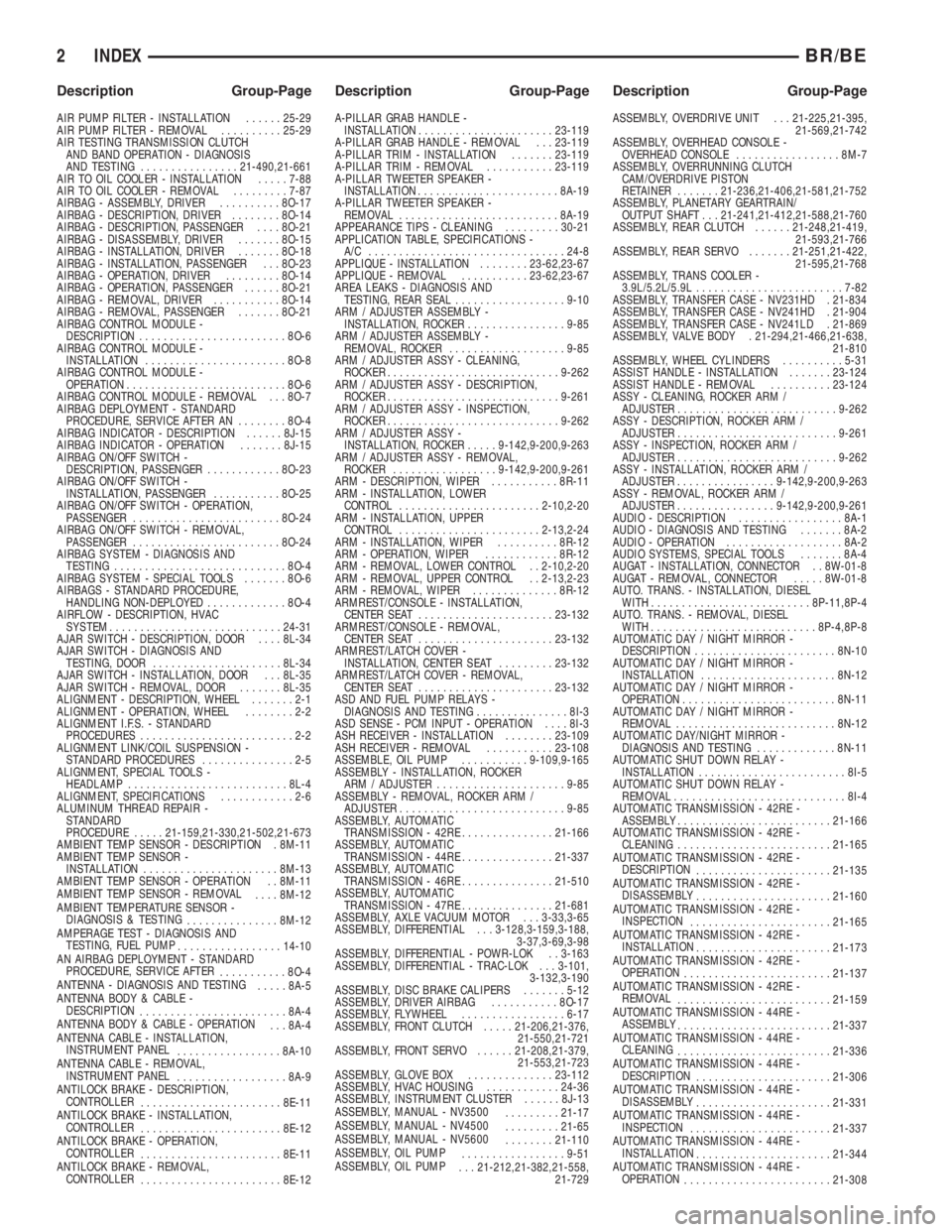
AIR PUMP FILTER - INSTALLATION......25-29
AIR PUMP FILTER - REMOVAL..........25-29
AIR TESTING TRANSMISSION CLUTCH
AND BAND OPERATION - DIAGNOSIS
AND TESTING................21-490,21-661
AIR TO OIL COOLER - INSTALLATION.....7-88
AIR TO OIL COOLER - REMOVAL.........7-87
AIRBAG - ASSEMBLY, DRIVER..........8O-17
AIRBAG - DESCRIPTION, DRIVER........8O-14
AIRBAG - DESCRIPTION, PASSENGER....8O-21
AIRBAG - DISASSEMBLY, DRIVER.......8O-15
AIRBAG - INSTALLATION, DRIVER.......8O-18
AIRBAG - INSTALLATION, PASSENGER . . . 8O-23
AIRBAG - OPERATION, DRIVER.........8O-14
AIRBAG - OPERATION, PASSENGER......8O-21
AIRBAG - REMOVAL, DRIVER...........8O-14
AIRBAG - REMOVAL, PASSENGER.......8O-21
AIRBAG CONTROL MODULE -
DESCRIPTION........................8O-6
AIRBAG CONTROL MODULE -
INSTALLATION.......................8O-8
AIRBAG CONTROL MODULE -
OPERATION..........................8O-6
AIRBAG CONTROL MODULE - REMOVAL . . . 8O-7
AIRBAG DEPLOYMENT - STANDARD
PROCEDURE, SERVICE AFTER AN........8O-4
AIRBAG INDICATOR - DESCRIPTION......8J-15
AIRBAG INDICATOR - OPERATION.......8J-15
AIRBAG ON/OFF SWITCH -
DESCRIPTION, PASSENGER............8O-23
AIRBAG ON/OFF SWITCH -
INSTALLATION, PASSENGER...........8O-25
AIRBAG ON/OFF SWITCH - OPERATION,
PASSENGER........................8O-24
AIRBAG ON/OFF SWITCH - REMOVAL,
PASSENGER........................8O-24
AIRBAG SYSTEM - DIAGNOSIS AND
TESTING............................8O-4
AIRBAG SYSTEM - SPECIAL TOOLS.......8O-6
AIRBAGS - STANDARD PROCEDURE,
HANDLING NON-DEPLOYED.............8O-4
AIRFLOW - DESCRIPTION, HVAC
SYSTEM............................24-31
AJAR SWITCH - DESCRIPTION, DOOR....8L-34
AJAR SWITCH - DIAGNOSIS AND
TESTING, DOOR.....................8L-34
AJAR SWITCH - INSTALLATION, DOOR . . . 8L-35
AJAR SWITCH - REMOVAL, DOOR.......8L-35
ALIGNMENT - DESCRIPTION, WHEEL.......2-1
ALIGNMENT - OPERATION, WHEEL........2-2
ALIGNMENT I.F.S. - STANDARD
PROCEDURES.........................2-2
ALIGNMENT LINK/COIL SUSPENSION -
STANDARD PROCEDURES...............2-5
ALIGNMENT, SPECIAL TOOLS -
HEADLAMP..........................8L-4
ALIGNMENT, SPECIFICATIONS............2-6
ALUMINUM THREAD REPAIR -
STANDARD
PROCEDURE.....21-159,21-330,21-502,21-673
AMBIENT TEMP SENSOR - DESCRIPTION . 8M-11
AMBIENT TEMP SENSOR -
INSTALLATION......................8M-13
AMBIENT TEMP SENSOR - OPERATION . . 8M-11
AMBIENT TEMP SENSOR - REMOVAL
....8M-12
AMBIENT TEMPERATURE SENSOR -
DIAGNOSIS & TESTING
...............8M-12
AMPERAGE TEST - DIAGNOSIS AND
TESTING, FUEL PUMP
.................14-10
AN AIRBAG DEPLOYMENT - STANDARD
PROCEDURE, SERVICE AFTER
...........8O-4
ANTENNA - DIAGNOSIS AND TESTING
.....8A-5
ANTENNA BODY & CABLE -
DESCRIPTION
........................8A-4
ANTENNA BODY & CABLE - OPERATION
. . . 8A-4
ANTENNA CABLE - INSTALLATION,
INSTRUMENT PANEL
.................8A-10
ANTENNA CABLE - REMOVAL,
INSTRUMENT PANEL
..................8A-9
ANTILOCK BRAKE - DESCRIPTION,
CONTROLLER
.......................8E-11
ANTILOCK BRAKE - INSTALLATION,
CONTROLLER
.......................8E-12
ANTILOCK BRAKE - OPERATION,
CONTROLLER
.......................8E-11
ANTILOCK BRAKE - REMOVAL,
CONTROLLER
.......................8E-12A-PILLAR GRAB HANDLE -
INSTALLATION......................23-119
A-PILLAR GRAB HANDLE - REMOVAL . . . 23-119
A-PILLAR TRIM - INSTALLATION.......23-119
A-PILLAR TRIM - REMOVAL...........23-119
A-PILLAR TWEETER SPEAKER -
INSTALLATION.......................8A-19
A-PILLAR TWEETER SPEAKER -
REMOVAL..........................8A-19
APPEARANCE TIPS - CLEANING.........30-21
APPLICATION TABLE, SPECIFICATIONS -
A/C ................................24-8
APPLIQUE - INSTALLATION........23-62,23-67
APPLIQUE - REMOVAL...........23-62,23-67
AREA LEAKS - DIAGNOSIS AND
TESTING, REAR SEAL..................9-10
ARM / ADJUSTER ASSEMBLY -
INSTALLATION, ROCKER................9-85
ARM / ADJUSTER ASSEMBLY -
REMOVAL, ROCKER...................9-85
ARM / ADJUSTER ASSY - CLEANING,
ROCKER............................9-262
ARM / ADJUSTER ASSY - DESCRIPTION,
ROCKER............................9-261
ARM / ADJUSTER ASSY - INSPECTION,
ROCKER............................9-262
ARM / ADJUSTER ASSY -
INSTALLATION, ROCKER.....9-142,9-200,9-263
ARM / ADJUSTER ASSY - REMOVAL,
ROCKER.................9-142,9-200,9-261
ARM - DESCRIPTION, WIPER...........8R-11
ARM - INSTALLATION, LOWER
CONTROL.......................2-10,2-20
ARM - INSTALLATION, UPPER
CONTROL.......................2-13,2-24
ARM - INSTALLATION, WIPER..........8R-12
ARM - OPERATION, WIPER............8R-12
ARM - REMOVAL, LOWER CONTROL . . 2-10,2-20
ARM - REMOVAL, UPPER CONTROL . . 2-13,2-23
ARM - REMOVAL, WIPER..............8R-12
ARMREST/CONSOLE - INSTALLATION,
CENTER SEAT......................23-132
ARMREST/CONSOLE - REMOVAL,
CENTER SEAT......................23-132
ARMREST/LATCH COVER -
INSTALLATION, CENTER SEAT.........23-132
ARMREST/LATCH COVER - REMOVAL,
CENTER SEAT......................23-132
ASD AND FUEL PUMP RELAYS -
DIAGNOSIS AND TESTING...............8I-3
ASD SENSE - PCM INPUT - OPERATION....8I-3
ASH RECEIVER - INSTALLATION........23-109
ASH RECEIVER - REMOVAL...........23-108
ASSEMBLE, OIL PUMP...........9-109,9-165
ASSEMBLY - INSTALLATION, ROCKER
ARM / ADJUSTER.....................9-85
ASSEMBLY - REMOVAL, ROCKER ARM /
ADJUSTER...........................9-85
ASSEMBLY, AUTOMATIC
TRANSMISSION - 42RE...............21-166
ASSEMBLY, AUTOMATIC
TRANSMISSION - 44RE...............21-337
ASSEMBLY, AUTOMATIC
TRANSMISSION - 46RE...............21-510
ASSEMBLY, AUTOMATIC
TRANSMISSION - 47RE...............21-681
ASSEMBLY, AXLE VACUUM MOTOR . . . 3-33,3-65
ASSEMBLY, DIFFERENTIAL . . . 3-128,3-159,3-188,
3-37,3-69,3-98
ASSEMBLY, DIFFERENTIAL - POWR-LOK . . 3-163
ASSEMBLY, DIFFERENTIAL - TRAC-LOK . . . 3-101,
3-132,3-190
ASSEMBLY, DISC BRAKE CALIPERS.......5-12
ASSEMBLY, DRIVER AIRBAG...........8O-17
ASSEMBLY, FLYWHEEL.................6-17
ASSEMBLY, FRONT CLUTCH.....21-206,21-376,
21-550,21-721
ASSEMBLY, FRONT SERVO......21-208,21-379,
21-553,21-723
ASSEMBLY, GLOVE BOX..............23-112
ASSEMBLY, HVAC HOUSING............24-36
ASSEMBLY, INSTRUMENT CLUSTER......8J-13
ASSEMBLY, MANUAL - NV3500
.........21-17
ASSEMBLY, MANUAL - NV4500
.........21-65
ASSEMBLY, MANUAL - NV5600
........21-110
ASSEMBLY, OIL PUMP
.................9-51
ASSEMBLY, OIL PUMP
. . . 21-212,21-382,21-558,
21-729ASSEMBLY, OVERDRIVE UNIT . . . 21-225,21-395,
21-569,21-742
ASSEMBLY, OVERHEAD CONSOLE -
OVERHEAD CONSOLE.................8M-7
ASSEMBLY, OVERRUNNING CLUTCH
CAM/OVERDRIVE PISTON
RETAINER.......21-236,21-406,21-581,21-752
ASSEMBLY, PLANETARY GEARTRAIN/
OUTPUT SHAFT . . . 21-241,21-412,21-588,21-760
ASSEMBLY, REAR CLUTCH......21-248,21-419,
21-593,21-766
ASSEMBLY, REAR SERVO.......21-251,21-422,
21-595,21-768
ASSEMBLY, TRANS COOLER -
3.9L/5.2L/5.9L........................7-82
ASSEMBLY, TRANSFER CASE - NV231HD . 21-834
ASSEMBLY, TRANSFER CASE - NV241HD . 21-904
ASSEMBLY, TRANSFER CASE - NV241LD . 21-869
ASSEMBLY, VALVE BODY . 21-294,21-466,21-638,
21-810
ASSEMBLY, WHEEL CYLINDERS..........5-31
ASSIST HANDLE - INSTALLATION.......23-124
ASSIST HANDLE - REMOVAL..........23-124
ASSY - CLEANING, ROCKER ARM /
ADJUSTER..........................9-262
ASSY - DESCRIPTION, ROCKER ARM /
ADJUSTER..........................9-261
ASSY - INSPECTION, ROCKER ARM /
ADJUSTER..........................9-262
ASSY - INSTALLATION, ROCKER ARM /
ADJUSTER................9-142,9-200,9-263
ASSY - REMOVAL, ROCKER ARM /
ADJUSTER................9-142,9-200,9-261
AUDIO - DESCRIPTION.................8A-1
AUDIO - DIAGNOSIS AND TESTING.......8A-2
AUDIO - OPERATION...................8A-2
AUDIO SYSTEMS, SPECIAL TOOLS.......8A-4
AUGAT - INSTALLATION, CONNECTOR . . 8W-01-8
AUGAT - REMOVAL, CONNECTOR.....8W-01-8
AUTO. TRANS. - INSTALLATION, DIESEL
WITH..........................8P-11,8P-4
AUTO. TRANS. - REMOVAL, DIESEL
WITH...........................8P-4,8P-8
AUTOMATIC DAY / NIGHT MIRROR -
DESCRIPTION.......................8N-10
AUTOMATIC DAY / NIGHT MIRROR -
INSTALLATION......................8N-12
AUTOMATIC DAY / NIGHT MIRROR -
OPERATION.........................8N-11
AUTOMATIC DAY / NIGHT MIRROR -
REMOVAL..........................8N-12
AUTOMATIC DAY/NIGHT MIRROR -
DIAGNOSIS AND TESTING.............8N-11
AUTOMATIC SHUT DOWN RELAY -
INSTALLATION........................8I-5
AUTOMATIC SHUT DOWN RELAY -
REMOVAL............................8I-4
AUTOMATIC TRANSMISSION - 42RE -
ASSEMBLY.........................21-166
AUTOMATIC TRANSMISSION - 42RE -
CLEANING.........................21-165
AUTOMATIC TRANSMISSION - 42RE -
DESCRIPTION
......................21-135
AUTOMATIC TRANSMISSION - 42RE -
DISASSEMBLY
......................21-160
AUTOMATIC TRANSMISSION - 42RE -
INSPECTION
.......................21-165
AUTOMATIC TRANSMISSION - 42RE -
INSTALLATION
......................21-173
AUTOMATIC TRANSMISSION - 42RE -
OPERATION
........................21-137
AUTOMATIC TRANSMISSION - 42RE -
REMOVAL
.........................21-159
AUTOMATIC TRANSMISSION - 44RE -
ASSEMBLY
.........................21-337
AUTOMATIC TRANSMISSION - 44RE -
CLEANING
.........................21-336
AUTOMATIC TRANSMISSION - 44RE -
DESCRIPTION
......................21-306
AUTOMATIC TRANSMISSION - 44RE -
DISASSEMBLY
......................21-331
AUTOMATIC TRANSMISSION - 44RE -
INSPECTION
.......................21-337
AUTOMATIC TRANSMISSION - 44RE -
INSTALLATION
......................21-344
AUTOMATIC TRANSMISSION - 44RE -
OPERATION
........................21-308
2 INDEXBR/BE
Description Group-Page Description Group-Page Description Group-Page
Page 2864 of 2889
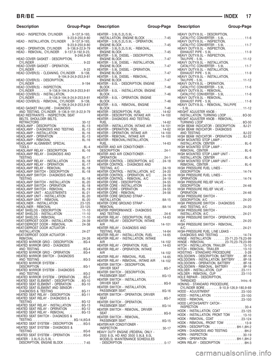
HEAD - INSPECTION, CYLINDER . . . 9-137,9-193,
9-23,9-250,9-80
HEAD - INSTALLATION, CYLINDER . 9-137,9-193,
9-23,9-250,9-80
HEAD - OPERATION, CYLINDER . 9-136,9-22,9-79
HEAD - REMOVAL, CYLINDER . 9-137,9-192,9-23,
9-246,9-80
HEAD COVER GASKET - DESCRIPTION,
CYLINDER...........................9-22
HEAD COVER GASKET - OPERATION,
CYLINDER...........................9-22
HEAD COVER(S) - CLEANING, CYLINDER . 9-138,
9-194,9-24,9-253,9-81
HEAD COVER(S) - DESCRIPTION,
CYLINDER..........................9-194
HEAD COVER(S) - INSPECTION,
CYLINDER........9-138,9-194,9-24,9-253,9-81
HEAD COVER(S) - INSTALLATION,
CYLINDER........9-138,9-194,9-24,9-253,9-81
HEAD COVER(S) - REMOVAL, CYLINDER . 9-138,
9-194,9-24,9-253,9-81
HEAD GASKET FAILURE - DIAGNOSIS
AND TESTING, CYLINDER . 9-136,9-191,9-22,9-79
HEAD RESTRAINTS - INSPECTION, SEAT
BELTS, SHOULDER BELTS,
RETRACTORS.......................30-12
HEADLAMP - DESCRIPTION............8L-13
HEADLAMP - DIAGNOSIS AND TESTING . . 8L-13
HEADLAMP - INSTALLATION............8L-16
HEADLAMP - OPERATION..............8L-13
HEADLAMP - REMOVAL...............8L-16
HEADLAMP ALIGNMENT, SPECIAL
TOOLS..............................8L-4
HEADLAMP RELAY - DESCRIPTION......8L-16
HEADLAMP RELAY - DIAGNOSIS AND
TESTING...........................8L-17
HEADLAMP RELAY - INSTALLATION......8L-18
HEADLAMP RELAY - OPERATION........8L-17
HEADLAMP RELAY - REMOVAL.........8L-18
HEADLAMP SWITCH - DESCRIPTION.....8L-18
HEADLAMP SWITCH - DIAGNOSIS AND
TESTING...........................8L-18
HEADLAMP SWITCH - INSTALLATION....8L-20
HEADLAMP SWITCH - OPERATION.......8L-18
HEADLAMP SWITCH - REMOVAL........8L-19
HEADLAMP UNIT - ADJUSTMENTS......8L-21
HEADLAMP UNIT - INSTALLATION.......8L-20
HEADLAMP UNIT - REMOVAL...........8L-20
HEADLINER - INSTALLATION..........23-125
HEADLINER - REMOVAL..............23-125
HEAT SHIELDS - DESCRIPTION.........11-10
HEAT SHIELDS - INSTALLATION.........11-10
HEAT SHIELDS - REMOVAL.............11-10
HEAT/DEFROST DOOR - INSTALLATION . . . 24-39
HEAT/DEFROST DOOR - REMOVAL.......24-38
HEAT/DEFROST DOOR ACTUATOR -
INSTALLATION.......................24-27
HEAT/DEFROST DOOR ACTUATOR -
REMOVAL..........................24-26
HEATED MIRROR GRID - DESCRIPTION . . . 8G-4
HEATED MIRROR GRID - DIAGNOSIS
AND TESTING........................8G-4
HEATED MIRROR GRID - OPERATION.....8G-4
HEATED MIRROR SWITCH - DIAGNOSIS
AND TESTING........................8G-3
HEATED MIRROR SYSTEM -
DESCRIPTION........................8G-1
HEATED MIRROR SYSTEM - DIAGNOSIS
AND TESTING........................8G-2
HEATED MIRROR SYSTEM - OPERATION . . . 8G-2
HEATED SEAT ELEMENT - DESCRIPTION . . 8G-10
HEATED SEAT ELEMENT - OPERATION....8G-10
HEATED SEAT ELEMENT AND SENSOR -
DIAGNOSIS & TESTING...............8G-11
HEATED SEAT RELAY - DESCRIPTION....8G-11
HEATED SEAT RELAY - DIAGNOSIS &
TESTING...........................8G-12
HEATED SEAT RELAY - INSTALLATION....8G-13
HEATED SEAT RELAY - OPERATION......8G-12
HEATED SEAT RELAY - REMOVAL.......8G-13
HEATED SEAT SWITCH - DIAGNOSIS &
TESTING
.......................8G-14,8G-8
HEATED SEAT SYSTEM - DESCRIPTION
....8G-5
HEATED SEAT SYSTEM - DIAGNOSIS &
TESTING
............................8G-6
HEATED SEAT SYSTEM - OPERATION
.....8G-6
HEATER - 3.9L/5.2L/5.9L -
DESCRIPTION, ENGINE BLOCK
...........7-45HEATER - 3.9L/5.2L/5.9L -
INSTALLATION, ENGINE BLOCK..........7-45
HEATER - 3.9L/5.2L/5.9L - OPERATION,
ENGINE BLOCK.......................7-45
HEATER - 3.9L/5.2L/5.9L - REMOVAL,
ENGINE BLOCK.......................7-45
HEATER - 5.9L DIESEL - DESCRIPTION,
ENGINE BLOCK.......................7-47
HEATER - 5.9L DIESEL - INSTALLATION,
ENGINE BLOCK.......................7-47
HEATER - 5.9L DIESEL - OPERATION,
ENGINE BLOCK.......................7-47
HEATER - 5.9L DIESEL - REMOVAL,
ENGINE BLOCK.......................7-47
HEATER - 8.0L - DESCRIPTION, ENGINE
BLOCK..............................7-46
HEATER - 8.0L - INSTALLATION, ENGINE
BLOCK..............................7-46
HEATER - 8.0L - OPERATION, ENGINE
BLOCK..............................7-46
HEATER - 8.0L - REMOVAL, ENGINE
BLOCK..............................7-46
HEATER - DESCRIPTION, FUEL..........14-62
HEATER - DESCRIPTION, INTAKE AIR....14-100
HEATER - DIAGNOSIS AND TESTING,
FUEL..............................14-62
HEATER - INSTALLATION, INTAKE AIR . . . 14-101
HEATER - OPERATION, FUEL............14-62
HEATER - OPERATION, INTAKE AIR.....14-100
HEATER - REMOVAL, INTAKE AIR.......14-100
HEATER - REMOVAL/INSTALLATION,
FUEL................................14-63
HEATER AND AIR CONDITIONER -
DESCRIPTION........................24-1
HEATER AND AIR CONDITIONER -
OPERATION..........................24-1
HEATER CONTROL - DESCRIPTION, A/C . . . 24-18
HEATER CONTROL - DIAGNOSIS AND
TESTING, A/C.......................24-19
HEATER CONTROL - INSTALLATION, A/C . . 24-20
HEATER CONTROL - OPERATION, A/C....24-18
HEATER CONTROL - REMOVAL, A/C......24-19
HEATER CORE - DESCRIPTION..........24-55
HEATER CORE - INSTALLATION.........24-56
HEATER CORE - OPERATION............24-55
HEATER CORE - REMOVAL.............24-56
HEATER CORE GROUND STRAP -
INSTALLATION.......................8A-15
HEATER CORE GROUND STRAP -
REMOVAL..........................8A-14
HEATER PERFORMANCE - DIAGNOSIS
AND TESTING........................24-6
HEATER RELAY - DESCRIPTION, FUEL....14-63
HEATER RELAY - DESCRIPTION, INTAKE
AIR ..............................14-101
HEATER RELAY - DIAGNOSIS AND
TESTING, FUEL......................14-64
HEATER RELAY - INSTALLATION, FUEL . . . 14-65
HEATER RELAY - INSTALLATION, INTAKE
AIR ..............................14-102
HEATER RELAY - OPERATION, FUEL......14-63
HEATER RELAY - OPERATION, INTAKE
AIR
..............................14-102
HEATER RELAY - REMOVAL, FUEL
.......14-65
HEATER RELAY - REMOVAL, INTAKE AIR
. 14-102
HEATER SWITCH - DESCRIPTION,
DRIVER SEAT
........................8G-7
HEATER SWITCH - DESCRIPTION,
PASSENGER SEAT
....................8G-13
HEATER SWITCH - INSTALLATION,
DRIVER SEAT
........................8G-9
HEATER SWITCH - INSTALLATION,
PASSENGER SEAT
....................8G-16
HEATER SWITCH - OPERATION, DRIVER
SEAT
...............................8G-7
HEATER SWITCH - OPERATION,
PASSENGER SEAT
....................8G-14
HEATER SWITCH - REMOVAL, DRIVER
SEAT
...............................8G-9
HEATER SWITCH - REMOVAL,
PASSENGER SEAT
....................8G-15
HEATER/AIR CONDITIONER -
INSPECTION
........................30-17
HEAVY DUTY ENGINE (FEDERAL ONLY -
2500 8.0L HD AND 3500 5.9L& 8.0L
MODELS) MAINTENANCE SCHEDULES
- DESCRIPTION
.......................0-17HEAVY DUTY/8.0L - DESCRIPTION,
CATALYTIC CONVERTER - 5.9L...........11-6
HEAVY DUTY/8.0L - INSPECTION,
CATALYTIC CONVERTER - 5.9L...........11-7
HEAVY DUTY/8.0L - INSPECTION,
EXHAUST PIPE - 5.9L..................11-9
HEAVY DUTY/8.0L - INSPECTION,
TAILPIPE - 5.9L......................11-12
HEAVY DUTY/8.0L - INSTALLATION,
CATALYTIC CONVERTER - 5.9L...........11-7
HEAVY DUTY/8.0L - INSTALLATION,
EXHAUST PIPE - 5.9L..................11-9
HEAVY DUTY/8.0L - INSTALLATION,
TAILPIPE - 5.9L......................11-12
HEAVY DUTY/8.0L - OPERATION,
CATALYTIC CONVERTER - 5.9L...........11-6
HEAVY DUTY/8.0L - REMOVAL,
CATALYTIC CONVERTER - 5.9L...........11-6
HEAVY DUTY/8.0L - REMOVAL,
EXHAUST PIPE - 5.9L..................11-8
HEAVY DUTY/8.0L - REMOVAL, TAILPIPE
- 5.9L..............................11-12
HEIGHT ADJUSTER KNOB -
INSTALLATION, TURNING LOOP.........8O-30
HEIGHT ADJUSTER KNOB - REMOVAL,
TURNING LOOP.....................8O-30
HIGH BEAM INDICATOR - DESCRIPTION . . 8J-21
HIGH BEAM INDICATOR - DIAGNOSIS
AND TESTING.......................8J-22
HIGH BEAM INDICATOR - OPERATION....8J-22
HIGH MOUNTED STOP LAMP -
INSTALLATION, CENTER................8L-6
HIGH MOUNTED STOP LAMP -
REMOVAL, CENTER....................8L-6
HIGH MOUNTED STOP LAMP UNIT -
INSTALLATION, CENTER................8L-6
HIGH MOUNTED STOP LAMP UNIT -
REMOVAL, CENTER....................8L-6
HIGH PRESSURE FUEL LINES -
DESCRIPTION.......................14-74
HIGH PRESSURE FUEL LINES -
OPERATION.........................14-74
HIGH PRESSURE RELIEF VALVE -
DESCRIPTION.......................24-46
HIGH PRESSURE RELIEF VALVE -
OPERATION.........................24-46
HIGH PRESSURE SWITCH -
DESCRIPTION, A/C...................24-20
HIGH PRESSURE SWITCH - DIAGNOSIS
AND TESTING, A/C...................24-20
HIGH PRESSURE SWITCH -
INSTALLATION, A/C...................24-21
HIGH PRESSURE SWITCH - OPERATION,
A/C................................24-20
HIGH PRESSURE SWITCH - REMOVAL,
A/C................................24-21
HIGH-PRESSURE FUEL LINE LEAKS -
DIAGNOSIS AND TESTING.............14-74
HINGE - INSTALLATION......23-71,23-79,23-99
HINGE - REMOVAL.........23-70,23-79,23-99
HITCH - INSTALLATION, TRAILER........13-10
HITCH - REMOVAL, TRAILER...........13-10
HOISTING - STANDARD PROCEDURE......0-28
HOLDDOWN - DESCRIPTION, BATTERY . . . 8F-18
HOLDDOWN - INSTALLATION, BATTERY . . . 8F-18
HOLDDOWN - OPERATION, BATTERY.....8F-18
HOLDDOWN - REMOVAL, BATTERY......8F-18
HOLDER - INSTALLATION, CUP........23-111
HOLDER - REMOVAL, CUP............23-110
HOLE REPAIR - DESCRIPTION,
THREADED........................Intro.-6
HONING - STANDARD PROCEDURE,
CYLINDER BORE........9-10,9-126,9-180,9-69
HOOD - ADJUSTMENT
...............23-100
HOOD - INSTALLATION
...............23-100
HOOD - REMOVAL
...................23-100
HOOD LATCH/SAFETY CATCH -
INSPECTION
.........................30-4
HOOK - INSTALLATION, COAT
..........23-125
HOOK - INSTALLATION, FRONT TOW
.....13-10
HOOK - REMOVAL, COAT
.............23-124
HOOK - REMOVAL, FRONT TOW
..........13-9
HORN - DESCRIPTION
.............8H-1,8H-2
HORN - DIAGNOSIS AND TESTING
.......8H-2
HORN - INSPECTION
..................30-19
HORN - OPERATION
...............8H-1,8H-2
HORN RELAY - DESCRIPTION
...........8H-3
BR/BEINDEX 17
Description Group-Page Description Group-Page Description Group-Page