turbo DODGE RAM 2001 Service User Guide
[x] Cancel search | Manufacturer: DODGE, Model Year: 2001, Model line: RAM, Model: DODGE RAM 2001Pages: 2889, PDF Size: 68.07 MB
Page 1386 of 2889
(9) Remove viscous fan/drive assembly (Refer to 7 -
COOLING/ENGINE/RADIATOR FAN - REMOVAL).
Remove the cooling fan and shroud together.
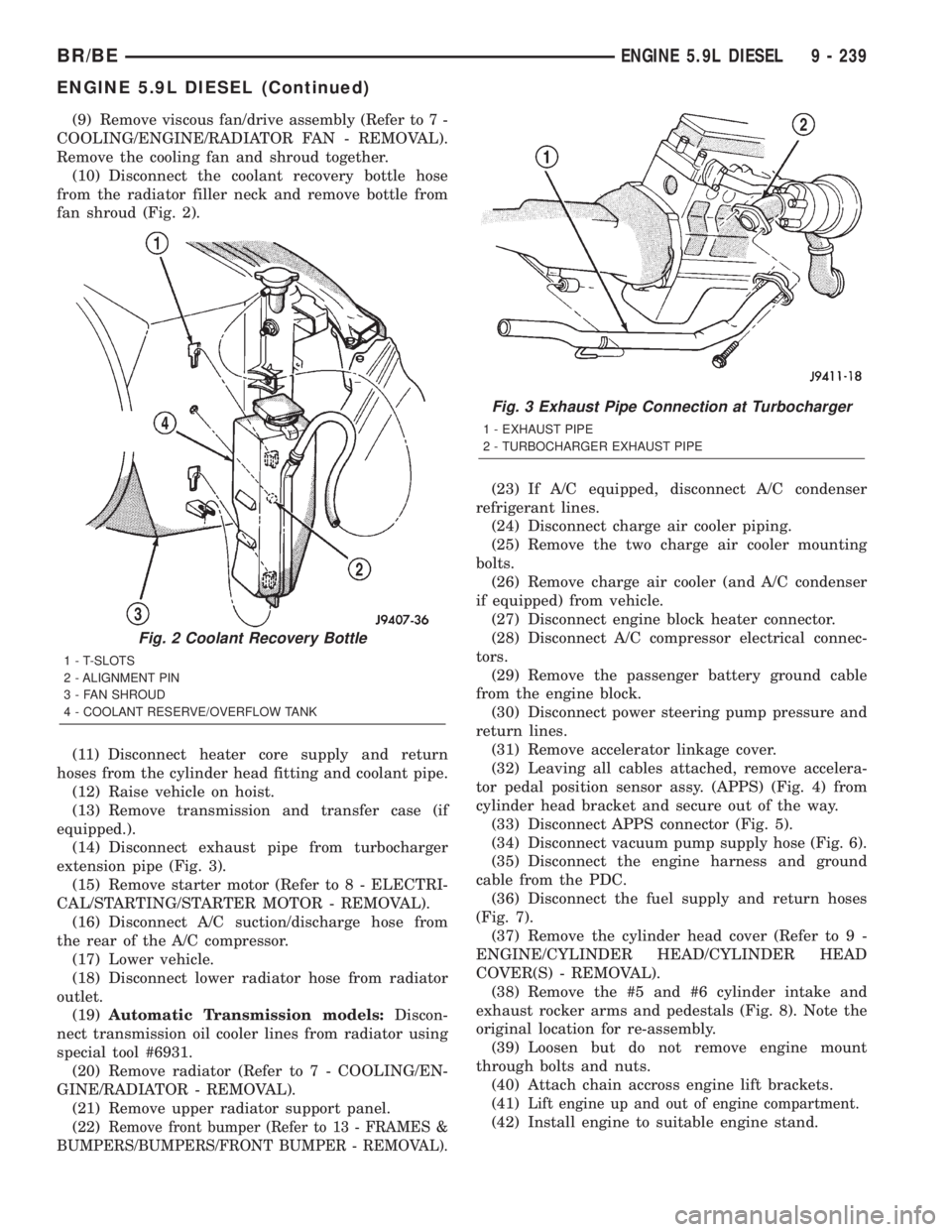
(10) Disconnect the coolant recovery bottle hose
from the radiator filler neck and remove bottle from
fan shroud (Fig. 2).
(11) Disconnect heater core supply and return
hoses from the cylinder head fitting and coolant pipe.
(12) Raise vehicle on hoist.
(13) Remove transmission and transfer case (if
equipped.).
(14) Disconnect exhaust pipe from turbocharger
extension pipe (Fig. 3).
(15) Remove starter motor (Refer to 8 - ELECTRI-
CAL/STARTING/STARTER MOTOR - REMOVAL).
(16) Disconnect A/C suction/discharge hose from
the rear of the A/C compressor.
(17) Lower vehicle.
(18) Disconnect lower radiator hose from radiator
outlet.
(19)Automatic Transmission models:Discon-
nect transmission oil cooler lines from radiator using
special tool #6931.
(20) Remove radiator (Refer to 7 - COOLING/EN-
GINE/RADIATOR - REMOVAL).
(21) Remove upper radiator support panel.
(22)
Remove front bumper (Refer to 13 - FRAMES &
BUMPERS/BUMPERS/FRONT BUMPER - REMOVAL).
(23) If A/C equipped, disconnect A/C condenser
refrigerant lines.
(24) Disconnect charge air cooler piping.
(25) Remove the two charge air cooler mounting
bolts.
(26) Remove charge air cooler (and A/C condenser
if equipped) from vehicle.
(27) Disconnect engine block heater connector.
(28) Disconnect A/C compressor electrical connec-
tors.
(29) Remove the passenger battery ground cable
from the engine block.
(30) Disconnect power steering pump pressure and
return lines.
(31) Remove accelerator linkage cover.
(32) Leaving all cables attached, remove accelera-
tor pedal position sensor assy. (APPS) (Fig. 4) from
cylinder head bracket and secure out of the way.
(33) Disconnect APPS connector (Fig. 5).
(34) Disconnect vacuum pump supply hose (Fig. 6).
(35) Disconnect the engine harness and ground
cable from the PDC.
(36) Disconnect the fuel supply and return hoses
(Fig. 7).
(37) Remove the cylinder head cover (Refer to 9 -
ENGINE/CYLINDER HEAD/CYLINDER HEAD
COVER(S) - REMOVAL).
(38) Remove the #5 and #6 cylinder intake and
exhaust rocker arms and pedestals (Fig. 8). Note the
original location for re-assembly.
(39) Loosen but do not remove engine mount
through bolts and nuts.
(40) Attach chain accross engine lift brackets.
(41)
Lift engine up and out of engine compartment.
(42) Install engine to suitable engine stand.
Fig. 2 Coolant Recovery Bottle
1 - T-SLOTS
2 - ALIGNMENT PIN
3 - FAN SHROUD
4 - COOLANT RESERVE/OVERFLOW TANK
Fig. 3 Exhaust Pipe Connection at Turbocharger
1 - EXHAUST PIPE
2 - TURBOCHARGER EXHAUST PIPE
BR/BEENGINE 5.9L DIESEL 9 - 239
ENGINE 5.9L DIESEL (Continued)
Page 1389 of 2889

(23) Connect the transmission quick-connect oil
cooler lines to the radiator. Push together until an
audible ªclickº is heard. Verify connection by pulling
apart.
(24) Raise vehicle.
(25) Connect a/c compressor suction/discharge hose
(if a/c equipped).
(26) Install the radiator lower hose and clamps.
(27) Install the starter motor (Refer to 8 - ELEC-
TRICAL/STARTING/STARTER MOTOR - INSTAL-
LATION).
(28) Install the transmission and transfer case (if
equipped).
(29) Connect the exhaust pipe to the turbocharger
elbow (Fig. 3). Torque the bolts to 34 N´m (25 ft. lbs.)
torque.
(30) Connect the transmission auxiliary oil cooler
lines (if equipped).
(31) Lower the vehicle
(32) Connect the heater core supply and return
hoses.
(33) Install the cooling fan and shroud at the same
time (Refer to 7 - COOLING/ENGINE/RADIATOR
FAN - INSTALLATION).
(34) Install the coolant recovery bottle to the fan
shroud (Fig. 2) and connect the hose to the radiator
filler neck.
(35) Install the windshield washer bottle to the fan
shroud and connect the pump supply hose and elec-
trical connections.
(36) Install the radiator upper hose and clamps.
(37) Change oil filter and install new engine oil.
(38) Fill cooling system with coolant (Refer to 7 -
COOLING - STANDARD PROCEDURE).
(39) Connect battery negative cables.
(40) Perform the fuel line air bleed procedure
(Refer to 14 - FUEL SYSTEM/FUEL DELIVERY -
STANDARD PROCEDURE).
(41) Start engine and inspect for engine oil, cool-
ant, and fuel leaks.
INSTALLATIONÐCRANKCASE BREATHER
VAPOR CANISTER
(1) Position vapor canister with strap over stud on
engine front cover. Install retaining nut. Tighten nut
10 N´m ( 89 in. lbs.).
(2) If removed, position hose onto crankcase
breather, then position clamp.
(3) Position lower portion of hose into vapor canis-
ter, then install and tighten cap.
SPECIFICATIONS
5.9L DIESEL
DESCRIPTION SPECIFICATION
Engine Type In-Line 6 Cyl. Turbo
Diesel
Bore and Stroke 102.0 X 120.0 mm
(4.02 X 4.72 in.)
Displacement 5.9L (359 cu. in.)
Compression Ratio
245 H.P. Version 17.0:1
235 H.P. Version 16.3:1
Horsepower (A/T and 5
Speed M/T)235 @ 2700 rpm
Horsepower (6 Speed M/T
Only)245 @ 2700 rpm
Torque Rating (A/T and 5
Speed M/T)460 ft. lbs. @ 1600 rpm
Torque Rating (6 Speed
M/T Only)505 ft. lbs. @ 1600 rpm
Firing Order 1-5-3-6-2-4
Lubrication System Pressure Feed-Full Flow
With Bypass Valve
Cylinder Block Cast Iron
Crankshaft Induction Hardened
Forged Steel
Cylinder Head Cast Iron With Valve
Seat Inserts
Combustion Chambers High Swirl Bowl
Camshaft Chilled Ductile Iron
Pistons Cast Aluminum
Connecting Rods Cross Rolled Micro Alloy
PISTONS AND CONNECTING RODS
Piston
Skirt Diameter 101.864 ± 101.88 mm
(4.0104 ± 4.011 in.)
Ring Groove Clearance
Intermediate (Max.) 0.095 mm (0.0037 in.)
Oil Control (Max.) 0.085 mm (0.0033 in.)
Piston Pins
Pin Diameter (Min.) 39.990 mm (1.5744 in.)
Bore Diameter (Max.) 40.025 mm (1.5758 in.)
Piston Ring End Gap
Top Ring 0.35 ± 0.45 mm
9 - 242 ENGINE 5.9L DIESELBR/BE
ENGINE 5.9L DIESEL (Continued)
Page 1392 of 2889
in air pressure due to an air cleaner element restric-
tion moves the diaphragm and the yellow disc will
indicate the size of the air drop.
CAUTION: Certain engine degreasers or cleaners
may discolor or damage the plastic housing of the
Filter Minder. Cover and tape the Filter Minder if any
engine degreasers or cleaners are to be used.
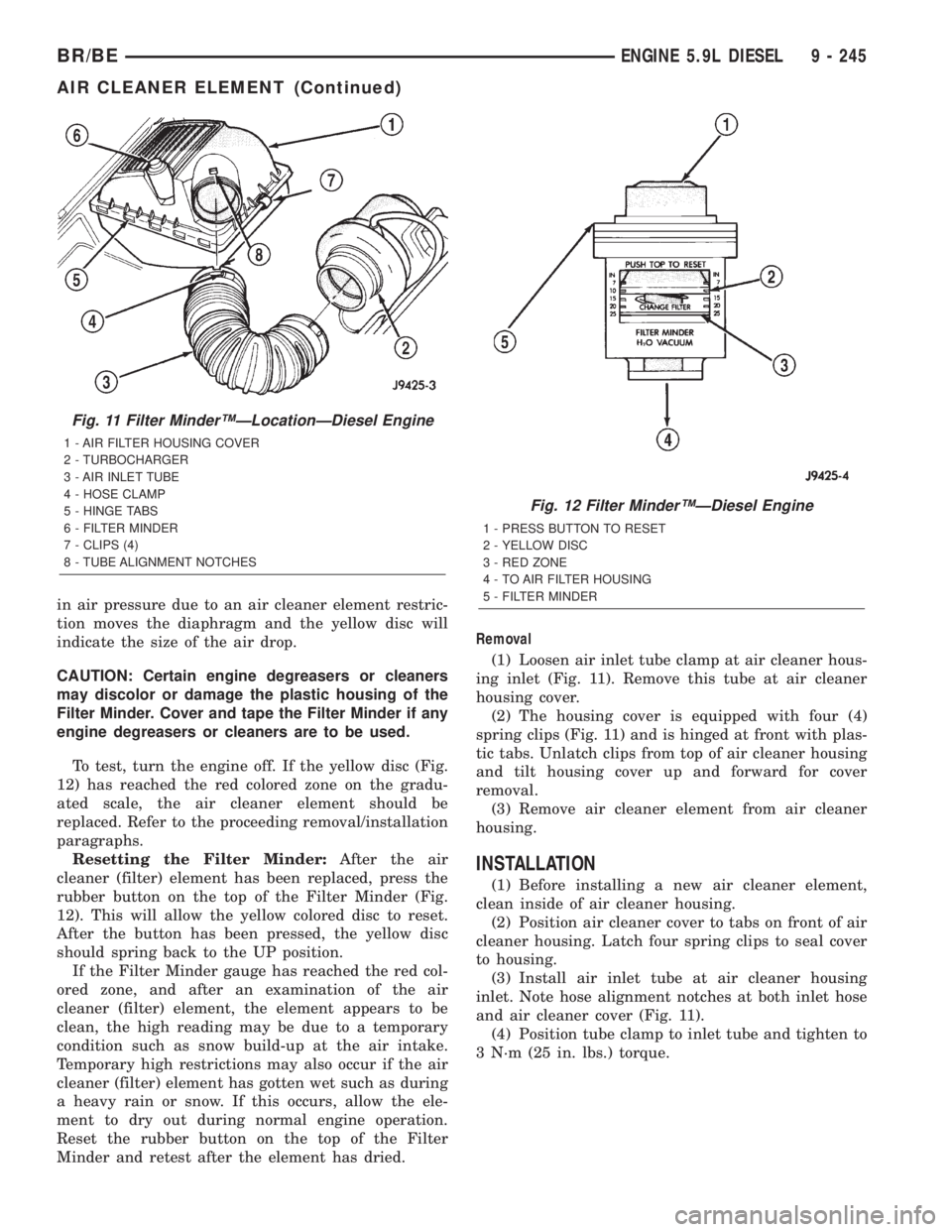
To test, turn the engine off. If the yellow disc (Fig.
12) has reached the red colored zone on the gradu-
ated scale, the air cleaner element should be
replaced. Refer to the proceeding removal/installation
paragraphs.
Resetting the Filter Minder:After the air
cleaner (filter) element has been replaced, press the
rubber button on the top of the Filter Minder (Fig.
12). This will allow the yellow colored disc to reset.
After the button has been pressed, the yellow disc
should spring back to the UP position.
If the Filter Minder gauge has reached the red col-
ored zone, and after an examination of the air
cleaner (filter) element, the element appears to be
clean, the high reading may be due to a temporary
condition such as snow build-up at the air intake.
Temporary high restrictions may also occur if the air
cleaner (filter) element has gotten wet such as during
a heavy rain or snow. If this occurs, allow the ele-
ment to dry out during normal engine operation.
Reset the rubber button on the top of the Filter
Minder and retest after the element has dried.Removal
(1) Loosen air inlet tube clamp at air cleaner hous-
ing inlet (Fig. 11). Remove this tube at air cleaner
housing cover.
(2) The housing cover is equipped with four (4)
spring clips (Fig. 11) and is hinged at front with plas-
tic tabs. Unlatch clips from top of air cleaner housing
and tilt housing cover up and forward for cover
removal.
(3) Remove air cleaner element from air cleaner
housing.
INSTALLATION
(1) Before installing a new air cleaner element,
clean inside of air cleaner housing.
(2) Position air cleaner cover to tabs on front of air
cleaner housing. Latch four spring clips to seal cover
to housing.
(3) Install air inlet tube at air cleaner housing
inlet. Note hose alignment notches at both inlet hose
and air cleaner cover (Fig. 11).
(4) Position tube clamp to inlet tube and tighten to
3 N´m (25 in. lbs.) torque.
Fig. 11 Filter MinderŸÐLocationÐDiesel Engine
1 - AIR FILTER HOUSING COVER
2 - TURBOCHARGER
3 - AIR INLET TUBE
4 - HOSE CLAMP
5 - HINGE TABS
6 - FILTER MINDER
7 - CLIPS (4)
8 - TUBE ALIGNMENT NOTCHES
Fig. 12 Filter MinderŸÐDiesel Engine
1 - PRESS BUTTON TO RESET
2 - YELLOW DISC
3 - RED ZONE
4 - TO AIR FILTER HOUSING
5 - FILTER MINDER
BR/BEENGINE 5.9L DIESEL 9 - 245
AIR CLEANER ELEMENT (Continued)
Page 1393 of 2889
CYLINDER HEAD
DESCRIPTION
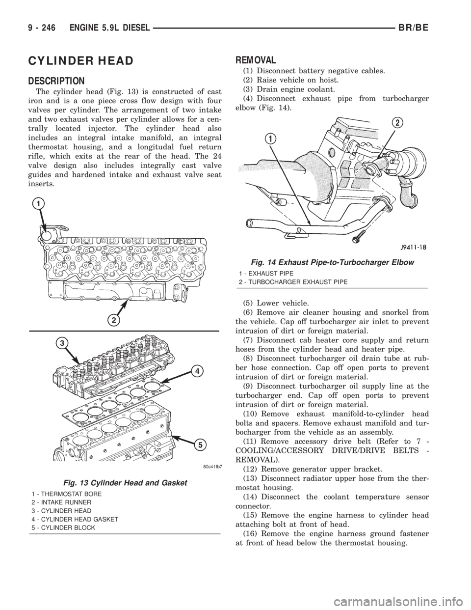
The cylinder head (Fig. 13) is constructed of cast
iron and is a one piece cross flow design with four
valves per cylinder. The arrangement of two intake
and two exhaust valves per cylinder allows for a cen-
trally located injector. The cylinder head also
includes an integral intake manifold, an integral
thermostat housing, and a longitudal fuel return
rifle, which exits at the rear of the head. The 24
valve design also includes integrally cast valve
guides and hardened intake and exhaust valve seat
inserts.
REMOVAL
(1) Disconnect battery negative cables.
(2) Raise vehicle on hoist.
(3) Drain engine coolant.
(4) Disconnect exhaust pipe from turbocharger
elbow (Fig. 14).
(5) Lower vehicle.
(6) Remove air cleaner housing and snorkel from
the vehicle. Cap off turbocharger air inlet to prevent
intrusion of dirt or foreign material.
(7) Disconnect cab heater core supply and return
hoses from the cylinder head and heater pipe.
(8) Disconnect turbocharger oil drain tube at rub-
ber hose connection. Cap off open ports to prevent
intrusion of dirt or foreign material.
(9) Disconnect turbocharger oil supply line at the
turbocharger end. Cap off open ports to prevent
intrusion of dirt or foreign material.
(10) Remove exhaust manifold-to-cylinder head
bolts and spacers. Remove exhaust manifold and tur-
bocharger from the vehicle as an assembly.
(11) Remove accessory drive belt (Refer to 7 -
COOLING/ACCESSORY DRIVE/DRIVE BELTS -
REMOVAL).
(12) Remove generator upper bracket.
(13) Disconnect radiator upper hose from the ther-
mostat housing.
(14) Disconnect the coolant temperature sensor
connector.
(15) Remove the engine harness to cylinder head
attaching bolt at front of head.
(16) Remove the engine harness ground fastener
at front of head below the thermostat housing.
Fig. 13 Cylinder Head and Gasket
1 - THERMOSTAT BORE
2 - INTAKE RUNNER
3 - CYLINDER HEAD
4 - CYLINDER HEAD GASKET
5 - CYLINDER BLOCK
Fig. 14 Exhaust Pipe-to-Turbocharger Elbow
1 - EXHAUST PIPE
2 - TURBOCHARGER EXHAUST PIPE
9 - 246 ENGINE 5.9L DIESELBR/BE
Page 1399 of 2889
(e) Install the front line bundle (cyls. #1, 2, and
4) following the same procedure used for the rear
line bundle.
(f) Torque the connections at the cylinder head
first. Torque connections to 38 N´m (28 ft. lbs.).
(g) Torque the line connections at the injection
pump to 24 N´m (18 ft. lbs.).
(h) Install the injection line support bracket to
intake cover/cylinder head bolts and torque to 24
N´m (18 ft. lbs.).
(16) Install the engine lift bracket at the rear of
cylinder head. Torque to 77 N´m (57 ft. lbs.).
(17) Install the fuel filter to injection pump low
pressure line. Inspect and replace sealing washers if
necessary. Torque banjo bolts to 24 N´m (18 ft. lbs.).
(18) Using new gaskets, install the intake grid
heater and air inlet housing. Torque bolts to 24 N´m
(18 ft. lbs.).
(19) Connect the APPS connector (Fig. 17).
(20) Install the APPS assembly. to the cylinder
head bracket and torque bolts to 12 N´m (105 in.
lbs.).
(21) Install the throttle linkage cover (Fig. 15).
(22) Install the charge air cooler-to-air inlet hous-
ing duct assembly. Torque all clamps to 11 N´m (100
in. lbs.).
(23) Connect intake grid heater wires.
(24) Fasten engine harness to front of cylinder
head with bolt.
(25) Install engine harness ground wire and torque
bolt to 24 N´m (18 ft. lbs.).
(26) Connect engine coolant temperature sensor
connector.
(27) Connect radiator upper hose to thermostat
housing.
(28) Install generator upper bracket and torque
bolts to 41 N´m (31 ft. lbs.).
(29) Install accessory drive belt (Refer to 7 -
COOLING/ACCESSORY DRIVE/DRIVE BELTS -
INSTALLATION).
(30) Install exhaust manifold/turbocharger assem-
bly. and start all bolts/spacers by hand. Torque bolts
to 43 N´m (32 ft. lbs.).
(31) Connect turbocharger oil drain tube.
(32) Perform the turbocharger pre-lube procedure.
Refer to Group 11, Exhaust System and Turbo-
charger for the correct procedure.
(33) Connect the turbocharger oil supply line.
(34) Install air cleaner housing and duct.
(35) Raise vehicle on hoist.
(36) Install exhaust pipe to turbocharger elbow
(Fig. 14). Torque bolts to 34 N´m (25 ft. lbs.).
(37) Lower vehicle.
(38) Fill engine coolant (Refer to 7 - COOLING -
STANDARD PROCEDURE).
(39) Start engine and check for leaks.
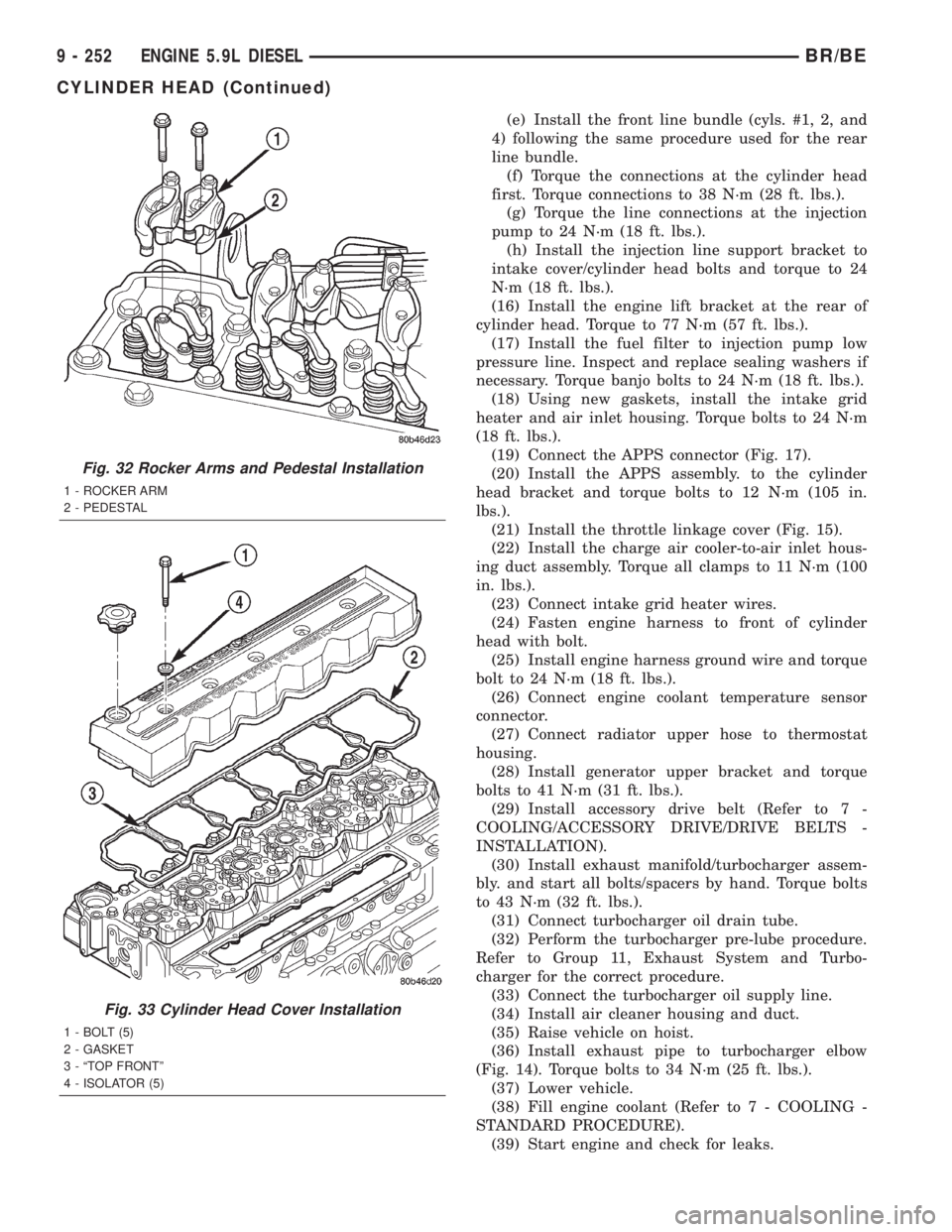
Fig. 32 Rocker Arms and Pedestal Installation
1 - ROCKER ARM
2 - PEDESTAL
Fig. 33 Cylinder Head Cover Installation
1 - BOLT (5)
2 - GASKET
3 - ªTOP FRONTº
4 - ISOLATOR (5)
9 - 252 ENGINE 5.9L DIESELBR/BE
CYLINDER HEAD (Continued)
Page 1439 of 2889
LUBRICATION
DESCRIPTION
NOTE: Refer to (Fig. 148) and (Fig. 149) for circuit
illustrations.
A gear driven gerotor type oil pump is mounted
behind the front gear cover in the lower right portion
on the engine.
OPERATION
A gerotor style oil pump draws oil from the crank-
case through the suction tube and delivers it through
the block where it enters the oil cooler cover and
pressure regulator valve. When oil pressure exceeds
449 kPa (65 PSI), the valve opens exposing the dump
port, which routes excess oil back to the oil sump.
At the same time, oil is directed to a cast in pas-
sage in the oil cooler cover, leading to the oil cooler
element. As the oil travels through the element
plates, it is cooled by engine coolant traveling past
the outside of the plates. It is then routed to the oil
filter head and through a full flow oil filter. If a
plugged filter is encountered, the filter by-pass valve
opens, allowing unfiltered oil to lubricate the engine.
This condition can be avoided by frequent oil and fil-
ter changes, per the maintenance schedules found in
the owners manual. The by-pass valve is calibrated
to open when it sees a pressure drop of more than
344 kPa (50 psi) across the oil filter.The oil filter head then divides the oil between the
engine and the turbocharger. The turbocharger
receives filtered, cooled and pressurized oil through a
supply line from the filter head. The oil lubricates
the turbocharger and returns to the pan by way of a
drain tube connecting the bottom of the turbocharger
to a pressed in tube in the cylinder block.
Oil is then carried across the block to an angle
drilling which intersects the main oil rifle. The main
oil rifle runs the length of the block and delivers oil
to the crankshaft main journals and valve train. Oil
travels to the crankshaft through a series of transfer
drillings (one for each main bearing) and lubricates a
groove in the main bearing upper shell. From there
another drilling feeds the camshaft main journals.
The piston cooling nozzles are also supplied by the
main bearing upper shell. Crankshaft internal cross-
drillings supply oil to the connecting rod journals.
Another series of transfer drillings intersecting the
main oil rifle supply the valve train components. Oil
travels up the drilling, through a hole in the head
gasket, and through a drilling in the cylinder head
(one per cylinder), where it enters the rocker arm
pedestal and is divided between the intake and
exhaust rocker arm. Oil travels up and around the
rocker arm mounting bolt, and lubricates the rocker
shaft by cross drillings that intersect the mounting
bolt hole. Grooves at both ends of the rocker shaft
supply oil through the rocker arm where the oil trav-
els to the push rod and socket balls (Fig. 148) and
(Fig. 149).
9 - 292 ENGINE 5.9L DIESELBR/BE
Page 1443 of 2889
²Milky discoloration indicates coolant dilution.
(4) Clean the area around the oil filter head.
Remove the filter (Refer to 9 - ENGINE/LUBRICA-
TION/OIL FILTER - REMOVAL).
(5) Install new oil filter (Refer to 9 - ENGINE/LU-
BRICATION/OIL FILTER - INSTALLATION).
(6) Clean the drain plug and the sealing surface of
the pan. Check the condition of the threads and seal-
ing surface on the oil pan and drain plug.
(7) Install the drain plug. Tighten the plug to 60
N´m (44 ft. lbs.) torque.
(8) Use only High-Quality Multi-Viscosity lubricat-
ing oil in the Cummins Turbo Diesel engine. Choose
the correct oil for the operating conditions (Refer to
LUBRICATION & MAINTENANCE/FLUID TYPES -
DESCRIPTION).
(9) Fill the engine with the correct grade of new oil
(Refer to LUBRICATION & MAINTENANCE/FLUID
CAPACITIES - SPECIFICATIONS).
(10) Start the engine and operate it at idle for sev-
eral minutes. Check for leaks at the filter and drain
plug.
(11) Stop engine. Wait several minutes to allow the
oil to drain back to the pan and check the level
again.
USED ENGINE OIL DISPOSAL Care should be
exercised when disposing of used engine oil after
it has been drained from a vehicle's engine.
OIL COOLER & LINES
CLEANING AND INSPECTION
Clean the sealing surfaces.
Apply 483 kPa (70 psi) air pressure to the element
to check for leaks. If the element leaks, replace the
element.
OIL FILTER
REMOVAL
(1) Clean the area around the oil filter head.
Remove the filter using a 90-95 mm filter wrench.
(2) Clean the gasket surface of the filter head. The
filter canister O-Ring seal can stick on the filter
head. Make sure it is removed.
INSTALLATION
(1) Fill the oil filter element with clean oil before
installation. Use the same type oil that will be used
in the engine.
(2) Apply a light film of lubricating oil to the seal-
ing surface before installing the filter.CAUTION: Mechanical over-tightening may distort
the threads or damage the filter element seal.
(3) Install the filter until it contacts the sealing
surface of the oil filter adapter. Tighten filter an
additional ó turn.
OIL PAN
REMOVAL
(1) Disconnect the battery negative cables.
(2) Raise vehicle on hoist.
(3) Remove transmission and transfer case (if
equipped).
(4) Remove flywheel.
(5) Disconnect starter cables from starter motor.
(6) Remove starter motor (Refer to 8 - ELECTRI-
CAL/STARTING/STARTER MOTOR - REMOVAL)
and transmission adapter plate assembly.
WARNING: HOT OIL CAN CAUSE PERSONAL
INJURY.
(7) Drain the engine oil (Refer to 9 - ENGINE/LU-
BRICATION/OIL - STANDARD PROCEDURE).
(8) Install the oil pan drain plug with a new seal-
ing washer and tighten to 60 N´m (44 ft. lbs.) torque.
(9) Remove oil pan bolts, break the pan to block
seal, and lower pan slightly and remove oil suction
tube fasteners.
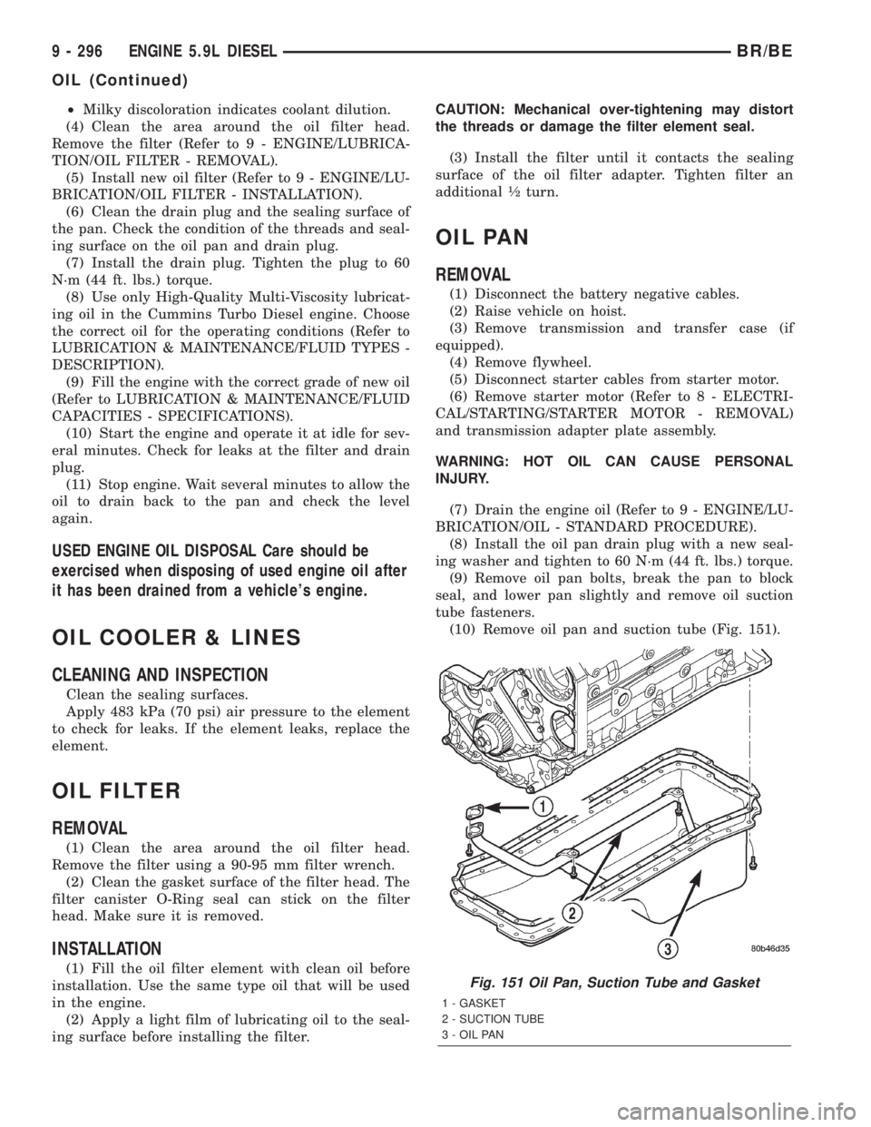
(10) Remove oil pan and suction tube (Fig. 151).
Fig. 151 Oil Pan, Suction Tube and Gasket
1 - GASKET
2 - SUCTION TUBE
3 - OIL PAN
9 - 296 ENGINE 5.9L DIESELBR/BE
OIL (Continued)
Page 1450 of 2889
(5) Using two (2) new gaskets, install the intake
air grid heater and air inlet housing (Fig. 168). Posi-
tion the ground cable and install and tighten the
bolts to 24 N´m (18 ft. lbs.) torque.
(6) Install and tighten the air intake heater power
supply nuts to 14 N´m (120 in. lbs.) torque.
(7) Install the engine oil dipstick tube and mount-
ing bolt (Fig. 167).
(8) Position the charge air cooler outlet tube onto
the air inlet housing (Fig. 167). Tighten the clamps
to 8 N´m (72 in. lbs.) torque.
(9) Perform the fuel system air bleed procedure
(Refer to 14 - FUEL SYSTEM/FUEL DELIVERY -
STANDARD PROCEDURE).
(10) Connect the battery negative cables.
EXHAUST MANIFOLD
REMOVAL
(1) Disconnect the battery negative cables.
(2) Raise vehicle on hoist.
(3) Disconnect the exhaust pipe from the turbo-
charger elbow (Fig. 170).
(4) Lower vehicle.
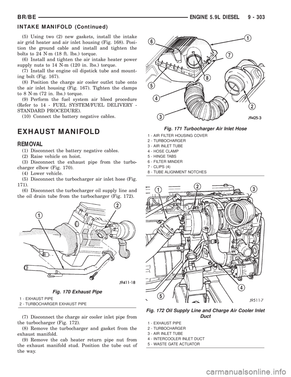
(5) Disconnect the turbocharger air inlet hose (Fig.
171).
(6) Disconnect the turbocharger oil supply line and
the oil drain tube from the turbocharger (Fig. 172).
(7) Disconnect the charge air cooler inlet pipe from
the turbocharger (Fig. 172).
(8) Remove the turbocharger and gasket from the
exhaust manifold.
(9) Remove the cab heater return pipe nut from
the exhaust manifold stud. Position the tube out of
the way.
Fig. 170 Exhaust Pipe
1 - EXHAUST PIPE
2 - TURBOCHARGER EXHAUST PIPE
Fig. 171 Turbocharger Air Inlet Hose
1 - AIR FILTER HOUSING COVER
2 - TURBOCHARGER
3 - AIR INLET TUBE
4 - HOSE CLAMP
5 - HINGE TABS
6 - FILTER MINDER
7 - CLIPS (4)
8 - TUBE ALIGNMENT NOTCHES
Fig. 172 Oil Supply Line and Charge Air Cooler Inlet
Duct
1 - EXHAUST PIPE
2 - TURBOCHARGER
3 - AIR INLET TUBE
4 - INTERCOOLER INLET DUCT
5 - WASTE GATE ACTUATOR
BR/BEENGINE 5.9L DIESEL 9 - 303
INTAKE MANIFOLD (Continued)
Page 1451 of 2889
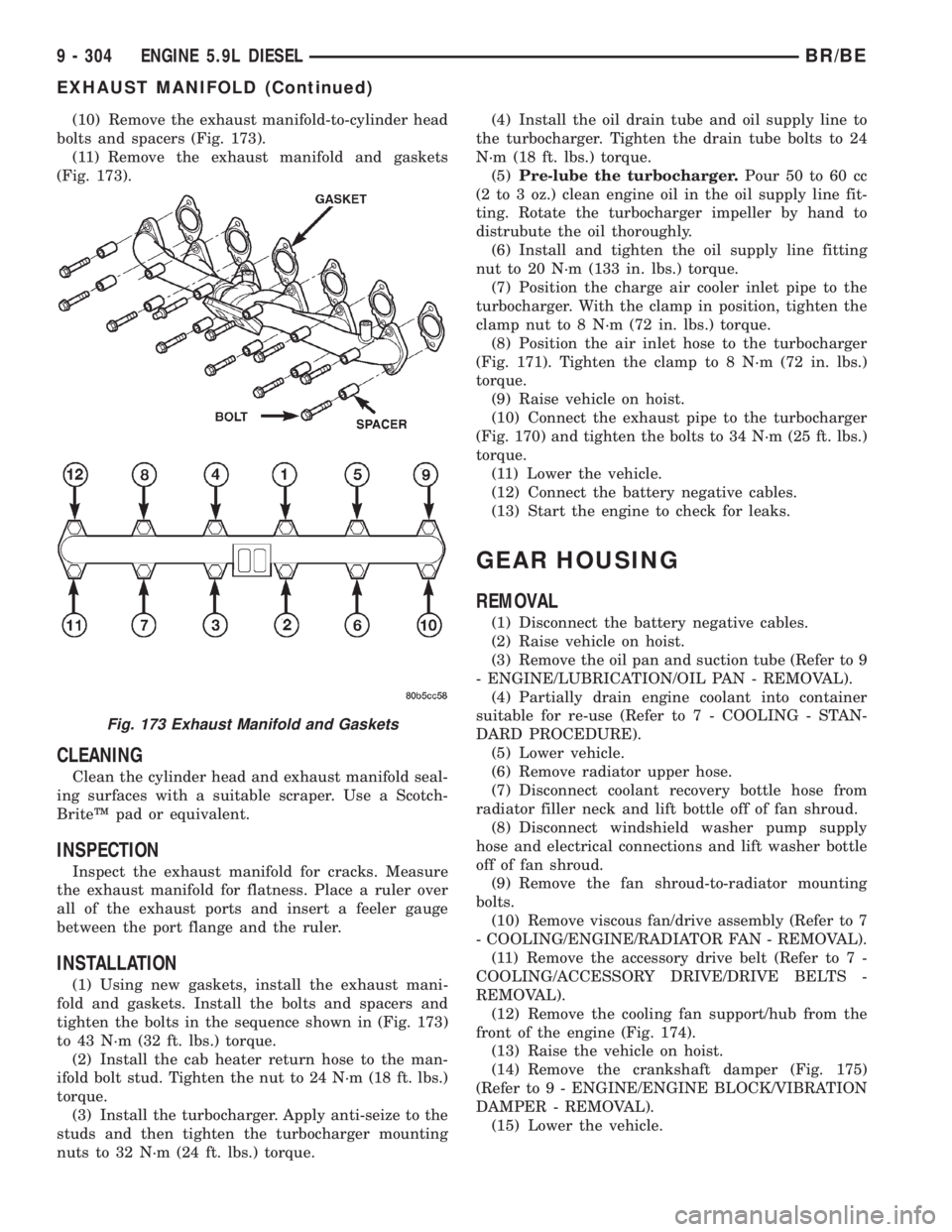
(10) Remove the exhaust manifold-to-cylinder head
bolts and spacers (Fig. 173).
(11) Remove the exhaust manifold and gaskets
(Fig. 173).
CLEANING
Clean the cylinder head and exhaust manifold seal-
ing surfaces with a suitable scraper. Use a Scotch-
BriteŸ pad or equivalent.
INSPECTION
Inspect the exhaust manifold for cracks. Measure
the exhaust manifold for flatness. Place a ruler over
all of the exhaust ports and insert a feeler gauge
between the port flange and the ruler.
INSTALLATION
(1) Using new gaskets, install the exhaust mani-
fold and gaskets. Install the bolts and spacers and
tighten the bolts in the sequence shown in (Fig. 173)
to 43 N´m (32 ft. lbs.) torque.
(2) Install the cab heater return hose to the man-
ifold bolt stud. Tighten the nut to 24 N´m (18 ft. lbs.)
torque.
(3) Install the turbocharger. Apply anti-seize to the
studs and then tighten the turbocharger mounting
nuts to 32 N´m (24 ft. lbs.) torque.(4) Install the oil drain tube and oil supply line to
the turbocharger. Tighten the drain tube bolts to 24
N´m (18 ft. lbs.) torque.
(5)Pre-lube the turbocharger.Pour 50 to 60 cc
(2 to 3 oz.) clean engine oil in the oil supply line fit-
ting. Rotate the turbocharger impeller by hand to
distrubute the oil thoroughly.
(6) Install and tighten the oil supply line fitting
nut to 20 N´m (133 in. lbs.) torque.
(7) Position the charge air cooler inlet pipe to the
turbocharger. With the clamp in position, tighten the
clamp nut to 8 N´m (72 in. lbs.) torque.
(8) Position the air inlet hose to the turbocharger
(Fig. 171). Tighten the clamp to 8 N´m (72 in. lbs.)
torque.
(9) Raise vehicle on hoist.
(10) Connect the exhaust pipe to the turbocharger
(Fig. 170) and tighten the bolts to 34 N´m (25 ft. lbs.)
torque.
(11) Lower the vehicle.
(12) Connect the battery negative cables.
(13) Start the engine to check for leaks.
GEAR HOUSING
REMOVAL
(1) Disconnect the battery negative cables.
(2) Raise vehicle on hoist.
(3) Remove the oil pan and suction tube (Refer to 9
- ENGINE/LUBRICATION/OIL PAN - REMOVAL).
(4) Partially drain engine coolant into container
suitable for re-use (Refer to 7 - COOLING - STAN-
DARD PROCEDURE).
(5) Lower vehicle.
(6) Remove radiator upper hose.
(7) Disconnect coolant recovery bottle hose from
radiator filler neck and lift bottle off of fan shroud.
(8) Disconnect windshield washer pump supply
hose and electrical connections and lift washer bottle
off of fan shroud.
(9) Remove the fan shroud-to-radiator mounting
bolts.
(10) Remove viscous fan/drive assembly (Refer to 7
- COOLING/ENGINE/RADIATOR FAN - REMOVAL).
(11) Remove the accessory drive belt (Refer to 7 -
COOLING/ACCESSORY DRIVE/DRIVE BELTS -
REMOVAL).
(12) Remove the cooling fan support/hub from the
front of the engine (Fig. 174).
(13) Raise the vehicle on hoist.
(14) Remove the crankshaft damper (Fig. 175)
(Refer to 9 - ENGINE/ENGINE BLOCK/VIBRATION
DAMPER - REMOVAL).
(15) Lower the vehicle.
Fig. 173 Exhaust Manifold and Gaskets
9 - 304 ENGINE 5.9L DIESELBR/BE
EXHAUST MANIFOLD (Continued)
Page 1456 of 2889
EXHAUST SYSTEM
TABLE OF CONTENTS
page page
EXHAUST SYSTEM
DESCRIPTION............................1
DIAGNOSIS AND TESTING..................4
GAS ENGINE...........................4
DIESEL ENGINE........................4
SPECIFICATIONS.........................5
CATALYTIC CONVERTER - 3.9L/5.2L/5.9L
DESCRIPTION............................5
OPERATION.............................5
REMOVAL...............................5
INSPECTION.............................5
INSTALLATION............................5
CATALYTIC CONVERTER - 5.9L HEAVY
DUTY/8.0L
DESCRIPTION............................6
OPERATION.............................6
REMOVAL...............................6
INSPECTION.............................7
INSTALLATION............................7
EXHAUST PIPE - 3.9L/5.2L/5.9L
REMOVAL...............................7
INSPECTION.............................7
INSTALLATION............................7
EXHAUST PIPE - 5.9L HEAVY DUTY/8.0L
REMOVAL...............................8
INSPECTION.............................9
INSTALLATION............................9
EXHAUST PIPE - 5.9L DIESEL
REMOVAL...............................9
INSPECTION.............................9
INSTALLATION...........................10
HEAT SHIELDS
DESCRIPTION...........................10
REMOVAL..............................10
INSTALLATION...........................10MUFFLER - 3.9L/5.2L/5.9L/8.0L
REMOVAL..............................10
INSTALLATION...........................11
MUFFLER - 5.9L DIESEL
REMOVAL..............................11
INSTALLATION...........................11
TAILPIPE - 3.9L/5.2L/5.9L
REMOVAL..............................11
INSPECTION............................11
INSTALLATION...........................12
TAILPIPE - 5.9L HEAVY DUTY/8.0L
REMOVAL..............................12
INSPECTION............................12
INSTALLATION...........................12
TAILPIPE - 5.9L DIESEL
REMOVAL..............................12
INSPECTION............................12
INSTALLATION...........................12
RESONATOR
REMOVAL..............................13
INSTALLATION...........................13
TURBOCHARGER
DESCRIPTION...........................13
OPERATION.............................13
REMOVAL..............................15
CLEANING..............................16
INSPECTION............................16
INSTALLATION...........................16
CHARGE AIR COOLER AND PLUMBING
DESCRIPTION...........................17
OPERATION.............................17
REMOVAL..............................17
CLEANING..............................18
INSPECTION............................18
INSTALLATION...........................18
EXHAUST SYSTEM
DESCRIPTIONÐ3.9L/5.2L/5.9/8.0L
CAUTION: Avoid application of rust prevention com-
pounds or undercoating materials to exhaust sys-tem floor pan exhaust heat shields. Light overspray
near the edges is permitted. Application of coating
will result in excessive floor pan temperatures and
objectionable fumes.
BR/BEEXHAUST SYSTEM 11 - 1