keyless entry DODGE RAM 2001 Service Repair Manual
[x] Cancel search | Manufacturer: DODGE, Model Year: 2001, Model line: RAM, Model: DODGE RAM 2001Pages: 2889, PDF Size: 68.07 MB
Page 425 of 2889
Refer to Electrical, Restraints for more information
on the clockspring. Refer to Electrical, Body Control/
Central Control Module for more information on the
Central Timer Module. Refer to the appropriate wir-
ing information. The wiring information includes wir-
ing diagrams, proper wire and connector repair
procedures, details of wire harness routing and
retention, connector pin-out information and location
views for the various wire harness connectors, splices
and grounds. Following are general descriptions of
the remaining major components in the standard and
optional factory-installed audio systems.
OPERATION
See the owner's manual in the vehicle glove box for
more information on the features, use and operation
of each of the available audio systems.
CENTRAL TIMER MODULE
The high-line or premium Central Timer Module
(CTM) can also control some features of the audio
system when the vehicle is equipped with the
optional RAZ radio receiver and remote radio
switches. A high-line CTM is used on high-line ver-
sions of this vehicle. A premium CTM is used on
vehicles equipped with the optional heated seats. The
CTM combines the functions of a chime/buzzer mod-
ule, an intermittent wipe module, an illuminated
entry module, a remote keyless entry module, and a
vehicle theft security system module in a single unit.
The high-line or premium CTM also controls and
integrates many of the additional electronic functions
and features included on models with this option.The RAZ radio receiver with a remote radio switch
option is one of the features that the CTM controls.
The CTM is programmed to send switch status mes-
sages over the Chrysler Collision Detection (CCD)
data bus to control the volume, seek, and pre-set sta-
tion advance functions of the RAZ radio receiver. The
CTM monitors the status of the remote radio
switches located on the steering wheel through a
hard wired circuit. The CTM then sends the proper
switch status messages to the radio receiver. The
electronic circuitry within the radio receiver responds
to the switch status messages it receives by adjusting
the radio settings as requested.
Refer to Electrical, Body Control/Central Timer
Module for more information on the high-line CTM.
Refer to Remote Radio Switch in Description and
Operation for more information on this component.
In addition, radio receivers connected to the CCD
data bus have several audio system functions that
can be diagnosed using a DRBIIItscan tool. Refer to
the proper Diagnostic Procedures manual for more
information on DRBIIIttesting of the audio systems.
DIAGNOSIS AND TESTING - AUDIO
WARNING: ON VEHICLES EQUIPPED WITH AIR-
BAGS, REFER TO ELECTRICAL, RESTRAINTS
BEFORE ATTEMPTING ANY STEERING WHEEL,
STEERING COLUMN, OR INSTRUMENT PANEL
COMPONENT DIAGNOSIS OR SERVICE. FAILURE
TO TAKE THE PROPER PRECAUTIONS COULD
RESULT IN ACCIDENTAL AIRBAG DEPLOYMENT
AND POSSIBLE PERSONAL INJURY.
8A - 2 AUDIOBR/BE
AUDIO (Continued)
Page 453 of 2889
external connector receptacles that connect it to the
vehicle electrical system through one (base) or two
(high-line/premium) take outs with connectors from
the instrument panel wire harness.
The base version of the CTM is used on base mod-
els of this vehicle. It is also sometimes referred to as
the Integrated Electronic Module (IEM). The base
version of the CTM combines the functions of a
chime module and an intermittent wipe module in a
single unit. The high-line version of the CTM is used
on high-line vehicles. The high-line CTM provides all
of the functions of the base version of the CTM, but
also is used to control and integrate many additional
electronic functions and features included on high-
line models. The premium version of the CTM is the
same as the high-line version, but is used only on
models equipped with the heated seat option.
The high-line and premium versions of the CTM
utilize integrated circuitry and information carried
on the Chrysler Collision Detection (CCD) data bus
network along with many hard wired inputs to mon-
itor many sensor and switch inputs throughout the
vehicle. In response to those inputs, the internal cir-
cuitry and programming of the CTM allow it to con-
trol and integrate many electronic functions and
features of the vehicle through both hard wired out-
puts and the transmission of electronic message out-
puts to other electronic modules in the vehicle over
the CCD data bus.
The features that the CTM supports or controls
include the following:
²Automatic Door Lock- The high-line/premium
CTM provides an optional automatic door lock fea-
ture (also known as rolling door locks). This is a pro-
grammable feature.
²Central Locking- The high-line/premium CTM
provides an optional central locking/unlocking fea-
ture.
²Chimes- All versions of the CTM provide chime
service through an integral chime tone generator.
²Courtesy Lamps- The high-line/premium CTM
provides courtesy lamp control with timed load shed-
ding.
²Door Lock Inhibit- The high-line/premium
CTM provides a door lock inhibit feature.
²Enhanced Accident Response- The high-line/
premium CTM provides an optional enhanced acci-
dent response feature. This is a programmable
feature.
²Heated Seats- The premium CTM controls the
optional heated seat system by controlling the opera-
tion of the heated seat relay.
²Illuminated Entry- The high-line/premium
CTM provides a timed illuminated entry feature.²Intermittent Wipe Control- All versions of
the CTM provide control of the intermittent wipe
delay, and wipe-after-wash features.
²Panic Mode- The high-line/premium CTM pro-
vides support for the optional RKE system panic
mode features.
²Power Lock Control- The high-line/premium
CTM provides the optional power lock system fea-
tures, including support for the automatic door lock
and door lock inhibit modes.
²Programmable Features- The high-line/pre-
mium CTM provides support for certain programma-
ble features.
²Remote Keyless Entry- The high-line/pre-
mium CTM provides the optional Remote Keyless
Entry (RKE) system features, including support for
the RKE Lock (with optional horn chirp), Unlock,
Panic, and illuminated entry modes, as well as the
ability to be programmed to recognize up to four
RKE transmitters. The RKE horn chirp is a program-
mable feature.
²Remote Radio Switch Interface- The high-
line/premium CTM monitors and transmits the sta-
tus of the optional remote radio switches.
²Speed Sensitive Intermittent Wipe Control-
The high-line/premium CTM provides the speed sen-
sitive intermittent wipe feature.
²Vehicle Theft Alarm- The high-line/premium
CTM provides control of the optional Vehicle Theft
Alarm features, including support for the central
locking/unlocking mode.
Hard wired circuitry connects the CTM to the elec-
trical system of the vehicle. These hard wired circuits
are integral to several wire harnesses, which are
routed throughout the vehicle and retained by many
different methods. These circuits may be connected to
each other, to the vehicle electrical system and to the
CTM through the use of a combination of soldered
splices, splice block connectors, and many different
types of wire harness terminal connectors and insu-
lators. Refer to the appropriate wiring information.
The wiring information includes wiring diagrams,
proper wire and connector repair procedures, further
details on wire harness routing and retention, as well
as pin-out and location views for the various wire
harness connectors, splices and grounds.
All versions of the CTM for this model are serviced
only as a complete unit. Many of the electronic fea-
tures in the vehicle controlled or supported by the
high-line or premium versions of the CTM are pro-
grammable using the DRBIIItscan tool. In addition,
the high-line/premium CTM software is Flash com-
patible, which means it can be reprogrammed using
Flash reprogramming procedures. However, if any of
the CTM hardware components are damaged or
faulty, the entire CTM unit must be replaced. The
8E - 2 ELECTRONIC CONTROL MODULESBR/BE
BODY CONTROL/CENTRAL TIMER MODULE (Continued)
Page 532 of 2889
HORN
TABLE OF CONTENTS
page page
HORN
DESCRIPTION............................1
OPERATION.............................1
HORN
DESCRIPTION............................2
OPERATION.............................2
DIAGNOSIS AND TESTING..................2
HORN................................2
REMOVAL...............................2
INSTALLATION............................3
HORN RELAY
DESCRIPTION............................3OPERATION.............................3
DIAGNOSIS AND TESTING..................3
HORN RELAY..........................3
REMOVAL...............................4
INSTALLATION............................4
HORN SWITCH
DESCRIPTION............................4
OPERATION.............................5
DIAGNOSIS AND TESTING..................5
HORN SWITCH.........................5
REMOVAL...............................5
HORN
DESCRIPTION
An electric horn system is standard factory-in-
stalled equipment on this model. Two horn systems
are offered on this model. The standard equipment
horn system features a single low-note electromag-
netic horn unit, while the optional dual horn system
features one low-note horn unit and one high-note
horn unit. Both horn systems use a non-switched
source of battery current so that the system will
remain functional, regardless of the ignition switch
position. The horn system includes the following com-
ponents:
²Clockspring
²High-line or premium Central Timer Module
(CTM)
²Horn(s)
²Horn relay
²Horn switch
(Refer to 8 - ELECTRICAL/RESTRAINTS/CLOCK-
SPRING - DESCRIPTION) for more information on
this component. (Refer to 8 - ELECTRICAL/ELEC-
TRONIC CONTROL MODULES/BODY CONTROL/
CENTRAL TIMER MODUL - DESCRIPTION) for
more information on this component. Refer to the
appropriate wiring information. The wiring informa-
tion includes wiring diagrams, proper wire and con-
nector repair procedures, details of wire harness
routing and retention, connector pin-out information
and location views for the various wire harness con-
nectors, splices and grounds. Following are general
descriptions of the remaining major components in
the horn system.
OPERATION
Each horn system is activated by a horn switch
concealed beneath the driver side airbag module trim
cover in the center of the steering wheel. Depressing
the center of the driver side airbag module trim cover
closes the horn switch. Closing the horn switch acti-
vates the horn relay. The activated horn relay then
switches the battery current needed to energize the
horn(s).
Refer to the owner's manual in the vehicle glove
box for more information on the features, use and
operation of the horn system.
CENTRAL TIMER MODULE
The high-line or premium Central Timer Module
(CTM) can also operate the horn system. A high-line
CTM is used on high-line versions of this vehicle. A
premium CTM is used on vehicles equipped with the
optional heated seats. The CTM combines the func-
tions of a chime/buzzer module, an intermittent wipe
module, an illuminated entry module, a remote key-
less entry module, and a vehicle theft security sys-
tem module in a single unit.
The high-line or premium CTM also controls and
integrates many of the additional electronic functions
and features included on models with this option.
The horn relay is one of the hard wired outputs of
the CTM. The high-line or premium CTM is pro-
grammed to energize or de-energize the horn relay in
response to certain inputs from the Vehicle Theft
Security System (VTSS) and/or the Remote Keyless
Entry (RKE) system.
(Refer to 8 - ELECTRICAL/ELECTRONIC CON-
TROL MODULES/BODY CONTROL/CENTRAL
TIMER MODUL - DESCRIPTION) for more informa-
BR/BEHORN 8H - 1
Page 535 of 2889
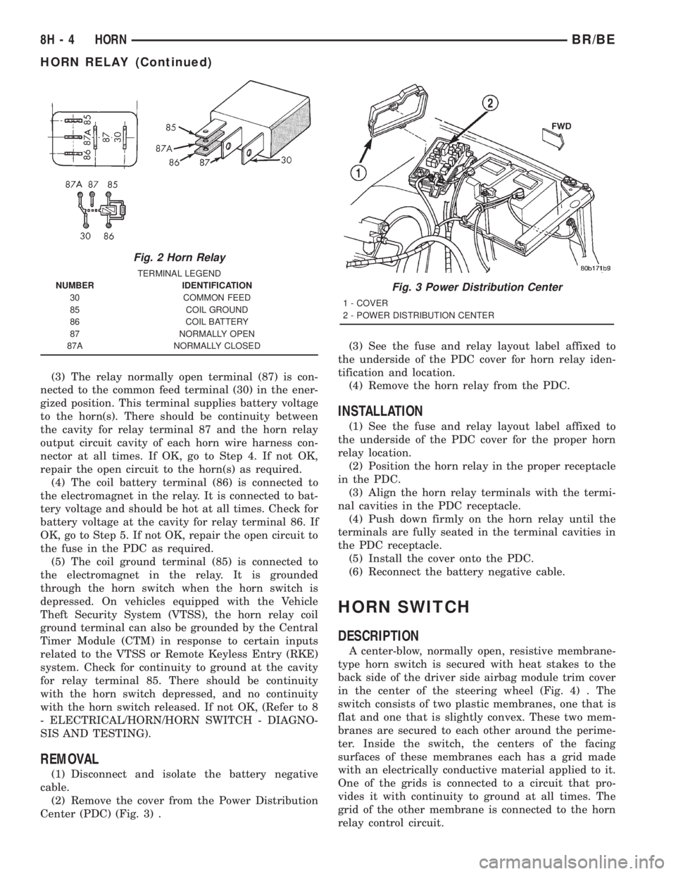
(3) The relay normally open terminal (87) is con-
nected to the common feed terminal (30) in the ener-
gized position. This terminal supplies battery voltage
to the horn(s). There should be continuity between
the cavity for relay terminal 87 and the horn relay
output circuit cavity of each horn wire harness con-
nector at all times. If OK, go to Step 4. If not OK,
repair the open circuit to the horn(s) as required.
(4) The coil battery terminal (86) is connected to
the electromagnet in the relay. It is connected to bat-
tery voltage and should be hot at all times. Check for
battery voltage at the cavity for relay terminal 86. If
OK, go to Step 5. If not OK, repair the open circuit to
the fuse in the PDC as required.
(5) The coil ground terminal (85) is connected to
the electromagnet in the relay. It is grounded
through the horn switch when the horn switch is
depressed. On vehicles equipped with the Vehicle
Theft Security System (VTSS), the horn relay coil
ground terminal can also be grounded by the Central
Timer Module (CTM) in response to certain inputs
related to the VTSS or Remote Keyless Entry (RKE)
system. Check for continuity to ground at the cavity
for relay terminal 85. There should be continuity
with the horn switch depressed, and no continuity
with the horn switch released. If not OK, (Refer to 8
- ELECTRICAL/HORN/HORN SWITCH - DIAGNO-
SIS AND TESTING).
REMOVAL
(1) Disconnect and isolate the battery negative
cable.
(2) Remove the cover from the Power Distribution
Center (PDC) (Fig. 3) .(3) See the fuse and relay layout label affixed to
the underside of the PDC cover for horn relay iden-
tification and location.
(4) Remove the horn relay from the PDC.
INSTALLATION
(1) See the fuse and relay layout label affixed to
the underside of the PDC cover for the proper horn
relay location.
(2) Position the horn relay in the proper receptacle
in the PDC.
(3) Align the horn relay terminals with the termi-
nal cavities in the PDC receptacle.
(4) Push down firmly on the horn relay until the
terminals are fully seated in the terminal cavities in
the PDC receptacle.
(5) Install the cover onto the PDC.
(6) Reconnect the battery negative cable.
HORN SWITCH
DESCRIPTION
A center-blow, normally open, resistive membrane-
type horn switch is secured with heat stakes to the
back side of the driver side airbag module trim cover
in the center of the steering wheel (Fig. 4) . The
switch consists of two plastic membranes, one that is
flat and one that is slightly convex. These two mem-
branes are secured to each other around the perime-
ter. Inside the switch, the centers of the facing
surfaces of these membranes each has a grid made
with an electrically conductive material applied to it.
One of the grids is connected to a circuit that pro-
vides it with continuity to ground at all times. The
grid of the other membrane is connected to the horn
relay control circuit.
Fig. 2 Horn Relay
TERMINAL LEGEND
NUMBER IDENTIFICATION
30 COMMON FEED
85 COIL GROUND
86 COIL BATTERY
87 NORMALLY OPEN
87A NORMALLY CLOSED
Fig. 3 Power Distribution Center
1 - COVER
2 - POWER DISTRIBUTION CENTER
8H - 4 HORNBR/BE
HORN RELAY (Continued)
Page 650 of 2889
POWER SYSTEMS
TABLE OF CONTENTS
page page
POWER LOCKS............................ 1
POWER MIRRORS........................ 10POWER SEAT SYSTEM..................... 15
POWER WINDOWS........................ 23
POWER LOCKS
TABLE OF CONTENTS
page page
POWER LOCKS
DESCRIPTION............................1
OPERATION.............................3
DIAGNOSIS AND TESTING..................4
POWER LOCK SYSTEM...................4
POWER LOCK & REMOTE KEYLESS
ENTRY SYSTEM.........................4
DOOR CYLINDER LOCK SWITCH
DESCRIPTION............................5
OPERATION.............................5
DIAGNOSIS AND TESTING..................5
DOOR CYLINDER LOCK SWITCH...........5
REMOVAL...............................6
INSTALLATION............................6
POWER LOCK MOTOR
DESCRIPTION............................6OPERATION.............................6
DIAGNOSIS AND TESTING..................7
POWER LOCK MOTOR...................7
REMOTE KEYLESS ENTRY TRANSMITTER
DESCRIPTION............................7
OPERATION.............................7
DIAGNOSIS AND TESTING..................7
REMOTE KEYLESS ENTRY TRANSMITTER....7
STANDARD PROCEDURE...................8
RKE TRANSMITTER PROGRAMMING........8
RKE TRANSMITTER BATTERIES............8
POWER LOCK SWITCH
DESCRIPTION............................8
OPERATION.............................8
DIAGNOSIS AND TESTING..................8
POWER LOCK SWITCH...................8
POWER LOCKS
DESCRIPTION - POWER LOCK SYSTEM
Two different power lock systems are offered as
optional factory-installed equipment on this model.
Both power lock systems are offered only on models
that are also equipped with power windows. On mod-
els without the optional Remote Keyless Entry (RKE)
system, a base version of the Central Timer Module
(CTM) is used. In this version of the power lock sys-
tem, the power lock switches provide the only control
over the operation of the power lock motors. On mod-
els with the optional RKE system, a high-line or pre-
mium version of the CTM is used to provide many
electronic features and conveniences that are not pos-
sible with the base version CTM. In this power lock
system, the power lock motors are controlled by the
microprocessor-based high-line or premium version ofthe CTM based upon the CTM programming and
electronic message inputs received from other elec-
tronic modules in the vehicle over the Chrysler Col-
lision Detection (CCD) data bus network, Radio
Frequency (RF) inputs received from the RKE trans-
mitters, as well as many hard wired inputs.
Both versions of the power lock system include the
following major components, which are described in
further detail elsewhere in this service manual:
²Power Lock Motors- A reversible electric
motor integral to the door latch of each front door
locks or unlocks the front door latch when provided
with the appropriate electrical inputs.
²Power Lock Switches- A power lock switch
integral to the power window/lock switch unit located
near the forward end of the arm rest on each front
door trim panel allows the power door lock system to
be operated by either the driver or the front seat pas-
senger.
BR/BEPOWER SYSTEMS 8N - 1
Page 651 of 2889
On those models equipped with the optional RKE
system, the power lock system also includes the fol-
lowing components, which are described in further
detail elsewhere in this service manual:
²Central Timer Module- The high-line or pre-
mium Central Timer Module (CTM) is located under
the driver side end of the instrument panel, inboard
of the instrument panel steering column opening.
The high-line or premium CTM contains a micropro-
cessor and software that allow it to provide the many
electronic functions and features not available with
base version of the power lock system.
²Door Cylinder Lock Switches- A resistor-
multiplexed switch located on the back of each front
door lock cylinder allows the power door lock system
to be operated using a key inserted in either the
driver or passenger front door lock cylinder.
Some of the additional features of the power lock
system found in vehicles with the RKE system option
include:
²Automatic Door Lock- The high-line/premium
CTM provides an optional automatic door lock fea-
ture (also known as rolling door locks). This is a pro-
grammable feature.
²Central Locking- The high-line/premium CTM
provides an optional central locking/unlocking fea-
ture.
²Door Lock Inhibit- The high-line/premium
CTM provides a door lock inhibit feature.
²Enhanced Accident Response- The high-line/
premium CTM provides an optional enhanced acci-
dent response feature. This is a programmable
feature.
Hard wired circuitry connects the power lock sys-
tem components to the electrical system of the vehi-
cle. These hard wired circuits are integral to several
wire harnesses, which are routed throughout the
vehicle and retained by many different methods.
These circuits may be connected to each other, to the
vehicle electrical system and to the power lock sys-
tem components through the use of a combination of
soldered splices, splice block connectors, and many
different types of wire harness terminal connectors
and insulators. Refer to the appropriate wiring infor-
mation. The wiring information includes wiring dia-
grams, proper wire and connector repair procedures,
further details on wire harness routing and reten-
tion, as well as pin-out and location views for the
various wire harness connectors, splices and grounds.
Many of the electronic features in the vehicle con-
trolled or supported by the high-line or premium ver-
sions of the CTM are programmable using the
DRBIIItscan tool. In addition, the high-line/pre-
mium CTM software is Flash compatible, which
means it can be reprogrammed using Flash repro-
gramming procedures. However, if any of the CTMhardware components are damaged or faulty, the
entire CTM unit must be replaced. The power lock
system components and the hard wired inputs or out-
puts of the CTM can be diagnosed using conventional
diagnostic tools and methods; however, for diagnosis
of the high-line or premium versions of the CTM or
the CCD data bus, the use of a DRBIIItscan tool is
required. Refer to the appropriate diagnostic infor-
mation.
DESCRIPTION - REMOTE KEYLESS ENTRY
SYSTEM
A Remote Keyless Entry (RKE) system is an avail-
able option on this model. The Remote Keyless Entry
(RKE) system is a Radio Frequency (RF) system that
allows the remote operation of the power lock system
and, if the vehicle is so equipped, the Vehicle Theft
Security System (VTSS). (Refer to 8 - ELECTRICAL/
VEHICLE THEFT SECURITY - DESCRIPTION).
The RKE system includes the following major compo-
nents, which are described in further detail else-
where in this service manual:
²Central Timer Module- The high-line or pre-
mium Central Timer Module (CTM) is located under
the driver side end of the instrument panel, inboard
of the instrument panel steering column opening.
The high-line or premium CTM contains a micropro-
cessor, an RF receiver, and the software that allow it
to provide the many electronic functions and features
of the RKE system.
²Keyless Entry Transmitter- The keyless
entry transmitter is a small, battery-powered, RF
transmitter that is contained within a molded plastic
case that is designed to also serve as a convenient
key fob.
Some additional features of the RKE system
include:
²Horn Chirp- This feature provides a short,
sharp chirp of the vehicle horn to give an audible
confirmation that a valid Lock signal has been
received from the RKE transmitter. This feature can
be enabled or disabled and, if enabled, one of two
optional horn chirp durations (twenty or forty milli-
seconds) can also be selected.
²Illuminated Entry- This feature turns on the
courtesy lamps in the vehicle for a timed interval
(about thirty seconds) each time a valid Unlock sig-
nal has been received from the RKE transmitter.
²Panic Mode- This feature allows the vehicle
operator to cause the vehicle horn to pulse, the head-
lights to flash, and the courtesy lamps to illuminate
for about three minutes by depressing a Panic button
on the RKE transmitter. Pressing the Panic button a
second time will cancel the Panic mode. A vehicle
speed of about 24 kilometers-per-hour (15 miles-per-
hour) will also cancel the panic mode.
8N - 2 POWER LOCKSBR/BE
POWER LOCKS (Continued)
Page 652 of 2889
OPERATION - POWER LOCK SYSTEM
All versions of the power lock system allow both
doors to be locked or unlocked electrically by operat-
ing the power lock switch on either front door trim
panel. On vehicles that are also equipped with the
optional Remote Keyless Entry (RKE) system, both
doors may also be locked or unlocked using a key in
either front door lock cylinder, or by using the RKE
transmitter. On vehicles with the RKE system, if cer-
tain features have been electronically enabled, the
locks may also be operated automatically by the
high-line or premium Central Timer Module (CTM)
based upon various other inputs. Those features and
their inputs are:
²Automatic Door Lock- If enabled, the high-
line/premium CTM will automatically lock the doors
when it receives a message from the Powertrain Con-
trol Module (PCM) indicating that the vehicle speed
is about 24 kilometers-per-hour (15 miles-per-hour)
or greater. The CTM also monitors the door ajar
switches, and will not activate the automatic door
lock feature until both doors have been closed for at
least five seconds. If this feature is enabled and a
door is opened after the vehicle is moving, the CTM
will also lock the doors five seconds after both doors
are closed.
²Central Locking- Vehicles equipped with a
high-line/premium CTM also have a resistor-multi-
plexed door cylinder lock switch mounted to the back
of the door lock cylinder within each front door. The
CTM continually monitors the input from these
switches to provide the central locking/unlocking fea-
ture. The CTM will automatically lock or unlock both
front doors when either front door is locked or
unlocked using a key.
²Door Lock Inhibit- The high-line/premium
CTM receives inputs from the key-in ignition switch,
the headlamp switch, and the door ajar switches. The
logic within the CTM allows it to monitor these
inputs to provide a door lock inhibit feature. The
door lock inhibit feature prevents the power lock sys-
tem from being energized with a power lock switch
input if the driver door is open with the headlamps
on or the key still in the ignition switch. However,
the locks can still be operated with the manual door
lock button or with a key in the door lock cylinder,
and the power locks will still operate using the RKE
transmitter while the driver door is open with the
headlamps on or a key in the ignition.
²Enhanced Accident Response- If enabled,
the high-line/premium CTM provides an enhanced
accident response feature. This feature uses elec-
tronic message inputs received by the CTM from the
Airbag Control Module (ACM) to determine when an
airbag has been deployed. The CTM also monitors
the state of the power lock system and the vehiclespeed messages from the PCM in order to provide
this feature. If the airbag has been deployed and the
vehicle has stopped moving, the CTM will automati-
cally unlock the doors, prevent the doors from being
locked, and turn on the courtesy lamps inside the
vehicle. Of course, these responses are dependent
upon a functional battery and electrical circuitry fol-
lowing the impact.
All versions of the power lock system operate on
battery current received through a fused B(+) circuit
from a fuse in the Junction Block (JB) so that the
system remains functional, regardless of the ignition
switch position. Also, in both versions of the power
lock system, each power lock switch receives battery
current independent of the other. In vehicles with the
base version of the power lock system, the driver side
power lock switch receives ground through the body
wire harness. A single wire take out of the body wire
harness with an eyelet terminal connector is secured
by a ground screw to the lower left B-pillar (regular
cab, extended cab) or lower left quarter inner panel
(quad cab). The passenger side power lock switch
receives ground through the driver side power lock
switch in the base version of the power lock system.
The base version power lock switches direct the
appropriate battery current and ground feeds to the
power lock motors. In the power lock system for vehi-
cles with the RKE system, the power lock switches
direct a battery current Lock or Unlock request sig-
nal to the high-line or premium CTM, and the CTM
energizes internal relays to direct the appropriate
battery current and ground feeds to the power lock
motors.
OPERATION - REMOTE KEYLESS ENTRY
SYSTEM
On vehicles with the Remote Keyless Entry (RKE)
system, the power locks can be operated remotely
using the RKE transmitter. If the vehicle is so
equipped, the RKE transmitter also arms and dis-
arms the factory-installed Vehicle Theft Security Sys-
tem (VTSS). Three small, recessed buttons on the
outside of the transmitter case labelled Lock, Unlock,
and Panic allow the user to choose the function that
is desired. The RKE transmitter then sends the
appropriate Radio Frequency (RF) signal. An RF
receiver that is integral to the high-line or premium
version of the Central Timer Module (CTM) receives
the transmitted signal, then uses its internal elec-
tronic programming to determine whether the
received signal is valid and what function has been
requested. If the signal is valid, the CTM provides
the programmed features.
Besides operating the power lock system and arm-
ing or disarming the VTSS, the RKE system also
controls the following features:
BR/BEPOWER LOCKS 8N - 3
POWER LOCKS (Continued)
Page 653 of 2889
²Horn Chirp- If this feature is enabled, the
CTM provides a horn chirp by internally pulling the
control coil of the horn relay to ground through a
hard wired circuit output.
²Illuminated Entry- The CTM provides illumi-
nated entry by internally controlling the current flow
to the courtesy lamps in the vehicle through a hard
wired output circuit.
²Panic Mode- The CTM provides the horn pulse
and headlight flash by internally pulling the control
coils of the horn relay and headlamp relay to ground
through hard wired circuit outputs. The CTM con-
trols the current flow to the courtesy lamps in the
vehicle through a hard wired output circuit. The
CTM also monitors the vehicle speed through elec-
tronic messages it receives from the Powertrain Con-
trol Module (PCM) over the Chrysler Collision
Detection (CCD) data bus network.
The RKE system operates on battery current received
through a fused B(+) circuit from a fuse in the Junction
Block (JB) so that the system remains functional,
regardless of the ignition switch position. The RKE sys-
tem can retain the vehicle access codes of up to four
RKE transmitters. The transmitter codes are retained
in RKE system memory, even if the battery is discon-
nected. If a transmitter is faulty or is lost, new trans-
mitter vehicle access codes can be programmed into the
system using a DRBIIItscan tool. Refer to the appro-
priate diagnostic information. Many of the electronic
features in the vehicle controlled or supported by the
high-line or premium versions of the CTM are program-
mable using the DRBIIItscan tool. In addition, the
high-line/premium CTM software is Flash compatible,
which means it can be reprogrammed using Flash
reprogramming procedures. However, if any of the CTM
hardware components are damaged or faulty, the entire
CTM unit must be replaced. The hard wired inputs or
outputs of the CTM can be diagnosed using conven-
tional diagnostic tools and methods; however, for diag-
nosis of the high-line or premium versions of the CTM
or the CCD data bus, the use of a DRBIIItscan tool is
required. Refer to the appropriate diagnostic informa-
tion.
DIAGNOSIS AND TESTING - POWER LOCK
SYSTEM
The following tests provide a preliminary diagnosis
for the power lock system usedonlyon vehicles
equipped with a base version of the Central Timer
Module (CTM). These testsdo notapply to the diag-
nosis of the power lock system used on vehicles
equipped with the optional Remote Keyless Entry
(RKE) system, which includes a high-line or premium
CTM. (Refer to 8 - ELECTRICAL/POWER LOCKS -
DIAGNOSIS AND TESTING - POWER LOCK &
REMOTE KEYLESS ENTRY SYSTEM). Refer to theappropriate wiring information. The wiring informa-
tion includes wiring diagrams, proper wire and con-
nector repair procedures, details of wire harness
routing and retention, connector pin-out information
and location views for the various wire harness con-
nectors, splices and grounds.
PRELIMINARY TESTS
To begin this test, note the system operation while
you actuate both the Lock and Unlock functions with
the power lock switches. Then, proceed as follows:
²If the entire power lock system fails to function
with both of the power lock switches, check the fused
B(+) fuse in the Junction Block (JB). If the fuse is
OK, check the ground circuit between the driver side
power lock switch and ground (G301). If the ground
circuit is OK, proceed to the diagnosis of the power
lock motors. (Refer to 8 - ELECTRICAL/POWER
LOCKS/POWER LOCK MOTOR - DIAGNOSIS AND
TESTING).
²If the entire power lock system fails to function
with only one of the power lock switches, proceed to
diagnosis of the power lock switches. (Refer to 8 -
ELECTRICAL/POWER LOCKS/POWER LOCK
SWITCH - DIAGNOSIS AND TESTING).
²If only one power lock motor fails to operate
with both power lock switches, proceed to diagnosis
of the power lock motor. (Refer to 8 - ELECTRICAL/
POWER LOCKS/POWER LOCK MOTOR - DIAGNO-
SIS AND TESTING).
DIAGNOSIS AND TESTING - POWER LOCK &
REMOTE KEYLESS ENTRY SYSTEM
The following tests include a preliminary diagnosis
for the power lock system usedonlyon vehicles
equipped with the optional Remote Keyless Entry
(RKE) system, which includes a high-line or premium
Central Timer Module (CTM). These testsdo not
apply to the diagnosis of the power lock system on
vehicles equipped with a base version of the CTM.
(Refer to 8 - ELECTRICAL/POWER LOCKS - DIAG-
NOSIS AND TESTING - POWER LOCK SYSTEM).
These tests will help to diagnose the hard wired
components and circuits of the power lock system.
However, these tests may not prove conclusive in the
diagnosis of this system. In order to obtain conclusive
testing of the power lock and RKE system, the
Chrysler Collision Detection (CCD) data bus network
and all of the electronic modules that provide inputs
to, or receive outputs from the power lock and RKE
system components must be checked.
The most reliable, efficient, and accurate means to
diagnose the power lock and RKE system requires the
use of a DRBIIItscan tool. The DRBIIItscan tool can
provide confirmation that the CCD data bus is func-
tional, that all of the electronic modules are sending
8N - 4 POWER LOCKSBR/BE
POWER LOCKS (Continued)
Page 654 of 2889
and receiving the proper messages on the CCD data
bus, that the CTM is receiving the proper hard wired
inputs, and that the power lock motors are being sent
the proper hard wired outputs by the CTM.
Refer to the appropriate wiring information. The
wiring information includes wiring diagrams, proper
wire and connector repair procedures, details of wire
harness routing and retention, connector pin-out
information and location views for the various wire
harness connectors, splices and grounds.
PRELIMINARY TESTS
To begin this test, note the system operation while
you actuate both the Lock and Unlock functions with
the power lock switches, the door cylinder lock switches,
and the RKE transmitter. Then, proceed as follows:
²If the entire power lock system fails to function
with the power lock switches, the door cylinder lock
switches, or the RKE transmitter, check the fused
B(+) fuse in the Junction Block (JB). If the fuse is
OK, proceed to the diagnosis of the power lock
motors. (Refer to 8 - ELECTRICAL/POWER LOCKS/
POWER LOCK MOTOR - DIAGNOSIS AND TEST-
ING).
²If the power lock system functions with both
power lock switches, and both door cylinder lock
switches, but not with the RKE transmitter, proceed
to the diagnosis of the transmitter. (Refer to 8 -
ELECTRICAL/POWER LOCKS/REMOTE KEYLESS
ENTRY TRANSMITTER - DIAGNOSIS AND TEST-
ING).
²
If the entire power lock system functions with the
RKE transmitter, and both door cylinder lock switches,
but not with one or both of the power lock switches, pro-
ceed to diagnosis of the power lock switches. (Refer to 8
- ELECTRICAL/POWER LOCKS/POWER LOCK
SWITCH - DIAGNOSIS AND TESTING).
²If the entire power lock system functions with
the RKE transmitter, and both power lock switches,
but not with one or both of the door cylinder lock
switches, proceed to diagnosis of the door cylinder
lock switches. (Refer to 8 - ELECTRICAL/POWER
LOCKS/DOOR CYLINDER LOCK SWITCH - DIAG-
NOSIS AND TESTING).
²If one power lock motor fails to operate with
both of the power lock switches, both of the door cyl-
inder lock switches and/or the RKE transmitter, pro-
ceed to diagnosis of the power lock motor. (Refer to 8
- ELECTRICAL/POWER LOCKS/POWER LOCK
MOTOR - DIAGNOSIS AND TESTING).
If the problem being diagnosed is related to one or
more of the electronic features (automatic locks, door
lock inhibit, enhanced accident response, illuminated
entry, panic mode, or RKE horn chirp), further diag-
nosis should be performed using a DRBIIItscan tool.
Refer to the appropriate diagnostic information.
DOOR CYLINDER LOCK
SWITCH
DESCRIPTION
A door cylinder lock switch is snapped onto the
back of the key lock cylinder inside each front door of
vehicles equipped with a high-line or premium Cen-
tral Timer Module (CTM). The door cylinder lock
switch is a resistor multiplexed momentary switch
that is hard wired in series between a body ground
and the CTM through the front door wire harness.
The door cylinder lock switches are driven by the key
lock cylinders and contain three internal resistors.
One resistor is used for the neutral switch position,
one for the Lock position, and one for the Unlock
position.
The door cylinder lock switches cannot be adjusted
or repaired and, if faulty or damaged, they must be
replaced.
OPERATION
The door cylinder lock switches are actuated by the
key lock cylinder when the key is inserted in the lock
cylinder and turned to the lock or unlock positions.
The door cylinder lock switch closes a path to ground
through one of three internal resistors for the Cen-
tral Timer Module (CTM) when the front door key
lock cylinder is in the Lock, Unlock, or Neutral posi-
tions. The CTM reads the switch status through an
internal pull-up, then uses this information as an
input for both power lock system and Vehicle Theft
Security System (VTSS) operation.
The door cylinder lock switches and circuits can be
diagnosed using conventional diagnostic tools and
methods.
DIAGNOSIS & TESTING - DOOR CYLINDER
LOCK SWITCH
Refer to the appropriate wiring information. The
wiring information includes wiring diagrams, proper
wire and connector repair procedures, details of wire
harness routing and retention, connector pin-out
information and location views for the various wire
harness connectors, splices and grounds.
(1) Disconnect the door cylinder lock switch pigtail
wire connector from the door wire harness connector.
(2) Using an ohmmeter, perform the switch resis-
tance checks between the two cavities of the door cyl-
inder lock switch pigtail wire connector. Actuate the
switch by rotating the key in the door lock cylinder
to test for the proper resistance values in each of the
three switch positions, as shown in the Door Cylinder
Lock Switch chart.
BR/BEPOWER LOCKS 8N - 5
POWER LOCKS (Continued)
Page 656 of 2889
DIAGNOSIS AND TESTING - POWER LOCK
MOTOR
On models with a base version of the Central
Timer Module (CTM), confirm proper power lock
switch operation before you proceed with this diagno-
sis. On models with a high-line or premium version
of the CTM, confirm proper power lock switch, power
lock switch output circuit, and CTM operation before
you proceed with this diagnosis. Remember, the
power lock switch controls the output to the power
lock motors on models with a base CTM, while the
CTM controls the output to the power lock motors on
models with a high-line or premium CTM. Refer to
the appropriate wiring information. The wiring infor-
mation includes wiring diagrams, proper wire and
connector repair procedures, details of wire harness
routing and retention, connector pin-out information
and location views for the various wire harness con-
nectors, splices and grounds.
(1) Check each power lock motor for correct opera-
tion while moving the power lock switch to both the
Lock and Unlock positions. If both of the power lock
motors are inoperative, go to Step 2. If one power
lock motor is inoperative, go to Step 3.
(2) If both of the power lock motors are inopera-
tive, the problem may be caused by one shorted
motor. Disconnecting a shorted power lock motor
from the power lock circuit will allow the good power
lock motors to operate. Disconnect the wire harness
connector from each power lock motor, one at a time,
and recheck both the lock and unlock functions by
operating the power lock switch. If both power lock
motors are still inoperative after the above test,
check for a short or open circuit between the power
lock motors and either the power lock switch (base
CTM) or the CTM (high-line or premium CTM). If
disconnecting one power lock motor causes the other
motor to become functional, go to Step 3 to test the
disconnected motor.
(3) Once it is determined which power lock motor
is inoperative, that motor can be tested as follows.
Disconnect the door wire harness connector from the
inoperative power lock motor. Apply 12 volts to the
lock and unlock driver circuit cavities of the power
lock motor pigtail wire connector to check its opera-
tion in one direction. Reverse the polarity to check
the motor operation in the opposite direction. If OK,
repair the shorted or open circuits between the power
lock motor and the power lock switch (base CTM) or
the CTM (high-line or premium CTM) as required. If
not OK, replace the faulty power lock motor.
REMOTE KEYLESS ENTRY
TRANSMITTER
DESCRIPTION
The Remote Keyless Entry (RKE) system Radio
Frequency (RF) transmitter is equipped with three
buttons, labeled Lock, Unlock, and Panic. It is also
equipped with a key ring and is designed to serve as
a key fob. The operating range of the transmitter
radio signal is up to 7 meters (23 feet) from the RKE
receiver. The RKE receiver is integral to the high-
line or premium Central Timer Module (CTM) in this
vehicle.
Each RKE transmitter has a different vehicle
access code, which must be programmed into the
memory of the RKE receiver in the vehicle in order
to operate the RKE system. The RKE receiver can
retain the access codes for up to four transmitters in
its memory. (Refer to 8 - ELECTRICAL/POWER
LOCKS/REMOTE KEYLESS ENTRY TRANSMIT-
TER - STANDARD PROCEDURE - RKE TRANS-
MITTER PROGRAMMING).
The RKE transmitter operates on two Duracell
DL2016, Panasonic CR2016 (or equivalent) batteries.
Typical battery life is from one to two years. The
RKE transmitter cannot be repaired and, if faulty or
damaged, it must be replaced.
OPERATION
See the owner's manual in the vehicle glove box for
more information on the features, use and operation
of the Remote Keyless Entry (RKE) transmitters.
DIAGNOSIS AND TESTING - REMOTE KEYLESS
ENTRY TRANSMITTER
(1) Replace the Remote Keyless Entry (RKE)
transmitter batteries. (Refer to 8 - ELECTRICAL/
POWER LOCKS/REMOTE KEYLESS ENTRY
TRANSMITTER - STANDARD PROCEDURE - RKE
TRANSMITTER BATTERIES). Test each of the RKE
transmitter functions. If OK, discard the faulty bat-
teries. If not OK, go to Step 2.
(2) Program the suspect RKE transmitter and
another known good transmitter into the RKE
receiver. (Refer to 8 - ELECTRICAL/POWER
LOCKS/REMOTE KEYLESS ENTRY TRANSMIT-
TER - STANDARD PROCEDURE - RKE TRANS-
MITTER PROGRAMMING).
(3) Test the RKE system operation with both
transmitters. If both transmitters fail to operate the
power lock system, a DRBIIItscan tool is required
for further diagnosis of the RKE system. Refer to the
appropriate diagnostic information. If the known
good RKE transmitter operates the power locks and
BR/BEPOWER LOCKS 8N - 7
POWER LOCK MOTOR (Continued)