sensor DODGE RAM 2001 Service Repair Manual
[x] Cancel search | Manufacturer: DODGE, Model Year: 2001, Model line: RAM, Model: DODGE RAM 2001Pages: 2889, PDF Size: 68.07 MB
Page 1835 of 2889
PROCEDURE ONE
(1) Transmission fluid must be at normal operat-
ing temperature for accurate fluid level check. Drive
vehicle if necessary to bring fluid temperature up to
normal hot operating temperature of 82ÉC (180ÉF).
(2) Position vehicle on level surface.
(3) Start and run engine at curb idle speed.
(4) Apply parking brakes.
(5) Shift transmission momentarily into all gear
ranges. Then shift transmission back to NEUTRAL.
(6) Clean top of filler tube and dipstick to keep
dirt from entering tube.
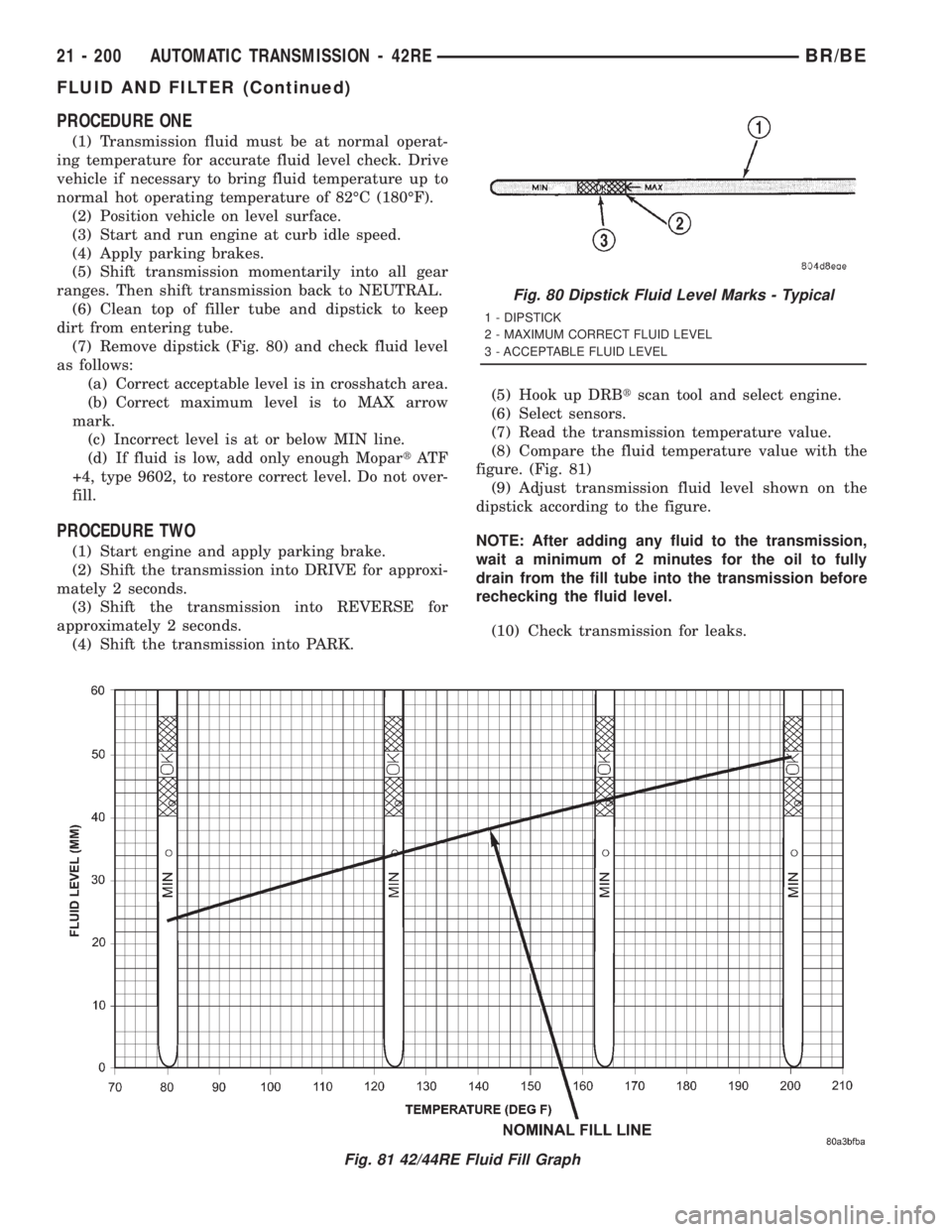
(7) Remove dipstick (Fig. 80) and check fluid level
as follows:
(a) Correct acceptable level is in crosshatch area.
(b) Correct maximum level is to MAX arrow
mark.
(c) Incorrect level is at or below MIN line.
(d) If fluid is low, add only enough MopartAT F
+4, type 9602, to restore correct level. Do not over-
fill.
PROCEDURE TWO
(1) Start engine and apply parking brake.
(2) Shift the transmission into DRIVE for approxi-
mately 2 seconds.
(3) Shift the transmission into REVERSE for
approximately 2 seconds.
(4) Shift the transmission into PARK.(5) Hook up DRBtscan tool and select engine.
(6) Select sensors.
(7) Read the transmission temperature value.
(8) Compare the fluid temperature value with the
figure. (Fig. 81)
(9) Adjust transmission fluid level shown on the
dipstick according to the figure.
NOTE: After adding any fluid to the transmission,
wait a minimum of 2 minutes for the oil to fully
drain from the fill tube into the transmission before
rechecking the fluid level.
(10) Check transmission for leaks.
Fig. 80 Dipstick Fluid Level Marks - Typical
1 - DIPSTICK
2 - MAXIMUM CORRECT FLUID LEVEL
3 - ACCEPTABLE FLUID LEVEL
Fig. 81 42/44RE Fluid Fill Graph
21 - 200 AUTOMATIC TRANSMISSION - 42REBR/BE
FLUID AND FILTER (Continued)
Page 1852 of 2889
DISASSEMBLY
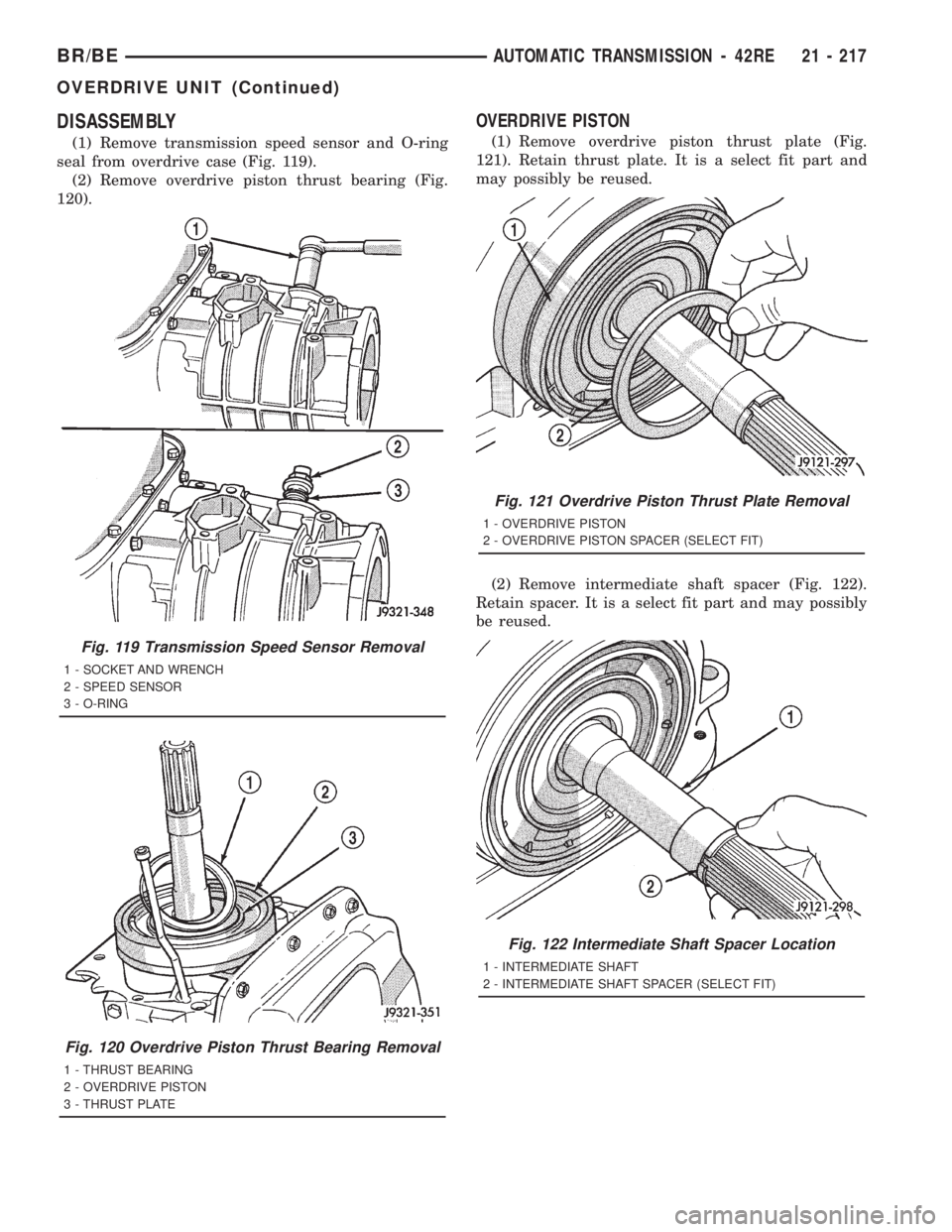
(1) Remove transmission speed sensor and O-ring
seal from overdrive case (Fig. 119).
(2) Remove overdrive piston thrust bearing (Fig.
120).
OVERDRIVE PISTON
(1) Remove overdrive piston thrust plate (Fig.
121). Retain thrust plate. It is a select fit part and
may possibly be reused.
(2) Remove intermediate shaft spacer (Fig. 122).
Retain spacer. It is a select fit part and may possibly
be reused.
Fig. 119 Transmission Speed Sensor Removal
1 - SOCKET AND WRENCH
2 - SPEED SENSOR
3 - O-RING
Fig. 120 Overdrive Piston Thrust Bearing Removal
1 - THRUST BEARING
2 - OVERDRIVE PISTON
3 - THRUST PLATE
Fig. 121 Overdrive Piston Thrust Plate Removal
1 - OVERDRIVE PISTON
2 - OVERDRIVE PISTON SPACER (SELECT FIT)
Fig. 122 Intermediate Shaft Spacer Location
1 - INTERMEDIATE SHAFT
2 - INTERMEDIATE SHAFT SPACER (SELECT FIT)
BR/BEAUTOMATIC TRANSMISSION - 42RE 21 - 217
OVERDRIVE UNIT (Continued)
Page 1868 of 2889
mounting hole cut into it. Be sure unit is facing
upward for access to direct clutch hub. Also be sure
output shaft is not loaded and internal components
are moved rearward for accurate measurement.
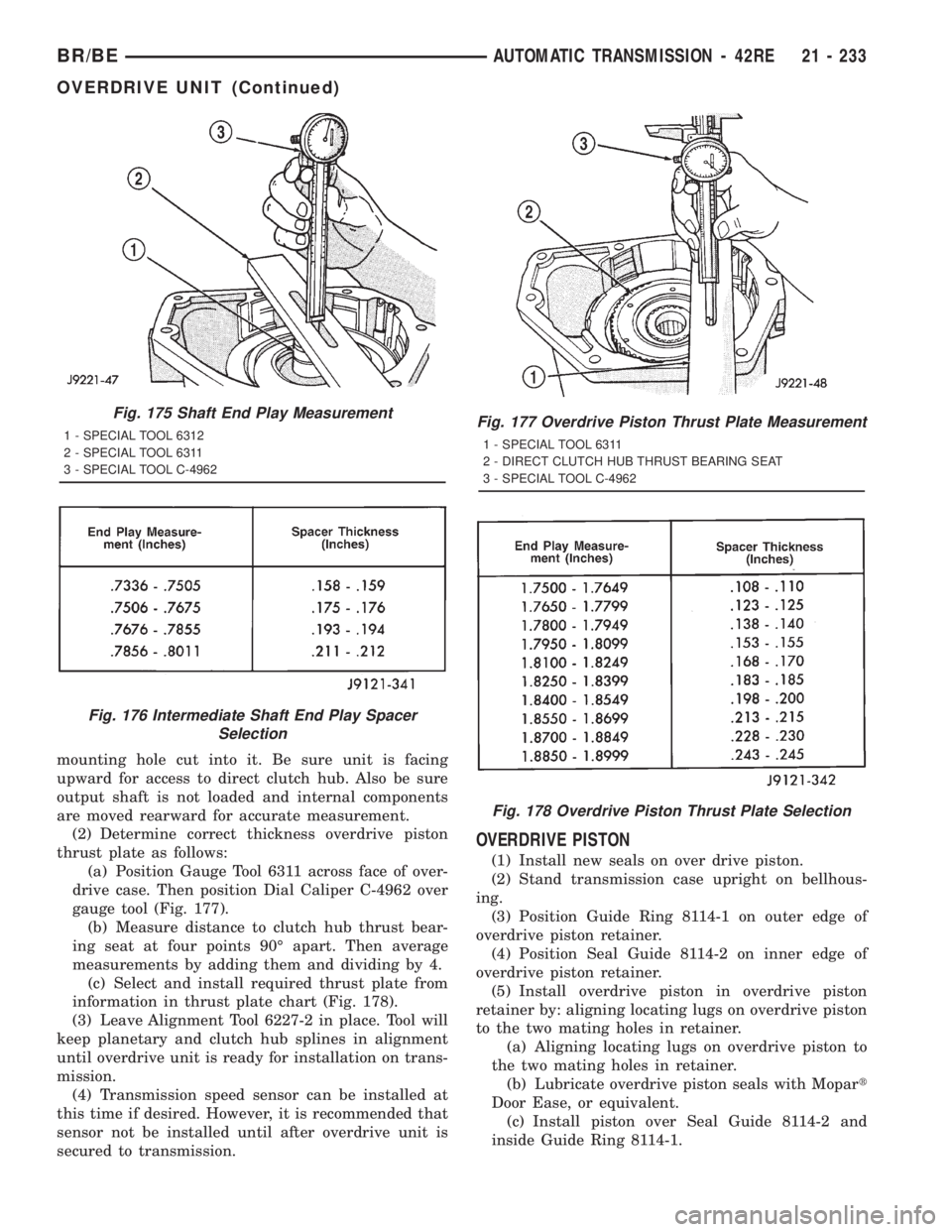
(2) Determine correct thickness overdrive piston
thrust plate as follows:
(a) Position Gauge Tool 6311 across face of over-
drive case. Then position Dial Caliper C-4962 over
gauge tool (Fig. 177).
(b) Measure distance to clutch hub thrust bear-
ing seat at four points 90É apart. Then average
measurements by adding them and dividing by 4.
(c) Select and install required thrust plate from
information in thrust plate chart (Fig. 178).
(3) Leave Alignment Tool 6227-2 in place. Tool will
keep planetary and clutch hub splines in alignment
until overdrive unit is ready for installation on trans-
mission.
(4) Transmission speed sensor can be installed at
this time if desired. However, it is recommended that
sensor not be installed until after overdrive unit is
secured to transmission.
OVERDRIVE PISTON
(1) Install new seals on over drive piston.
(2) Stand transmission case upright on bellhous-
ing.
(3) Position Guide Ring 8114-1 on outer edge of
overdrive piston retainer.
(4) Position Seal Guide 8114-2 on inner edge of
overdrive piston retainer.
(5) Install overdrive piston in overdrive piston
retainer by: aligning locating lugs on overdrive piston
to the two mating holes in retainer.
(a) Aligning locating lugs on overdrive piston to
the two mating holes in retainer.
(b) Lubricate overdrive piston seals with Mopart
Door Ease, or equivalent.
(c) Install piston over Seal Guide 8114-2 and
inside Guide Ring 8114-1.
Fig. 175 Shaft End Play Measurement
1 - SPECIAL TOOL 6312
2 - SPECIAL TOOL 6311
3 - SPECIAL TOOL C-4962
Fig. 176 Intermediate Shaft End Play Spacer
Selection
Fig. 177 Overdrive Piston Thrust Plate Measurement
1 - SPECIAL TOOL 6311
2 - DIRECT CLUTCH HUB THRUST BEARING SEAT
3 - SPECIAL TOOL C-4962
Fig. 178 Overdrive Piston Thrust Plate Selection
BR/BEAUTOMATIC TRANSMISSION - 42RE 21 - 233
OVERDRIVE UNIT (Continued)
Page 1869 of 2889
(d) Push overdrive piston into position in
retainer.
(e) Verify that the locating lugs entered the lug
bores in the retainer.
(6) Install intermediate shaft spacer on intermedi-
ate shaft.
(7) Install overdrive piston thrust plate on over-
drive piston.
(8) Install overdrive piston thrust bearing on over-
drive piston.
(9) Install transmission speed sensor and O-ring
seal in overdrive case (Fig. 119).
INSTALLATION
(1) Be sure overdrive unit Alignment Tool 6227-2
is fully seated before moving unit. If tool is not
seated and gear splines rotate out of alignment, over-
drive unit will have to be disassembled in order to
realign splines.
(2) If overdrive piston retainer was not removed
during service and original case gasket is no longer
reusable, prepare new gasket by trimming it.
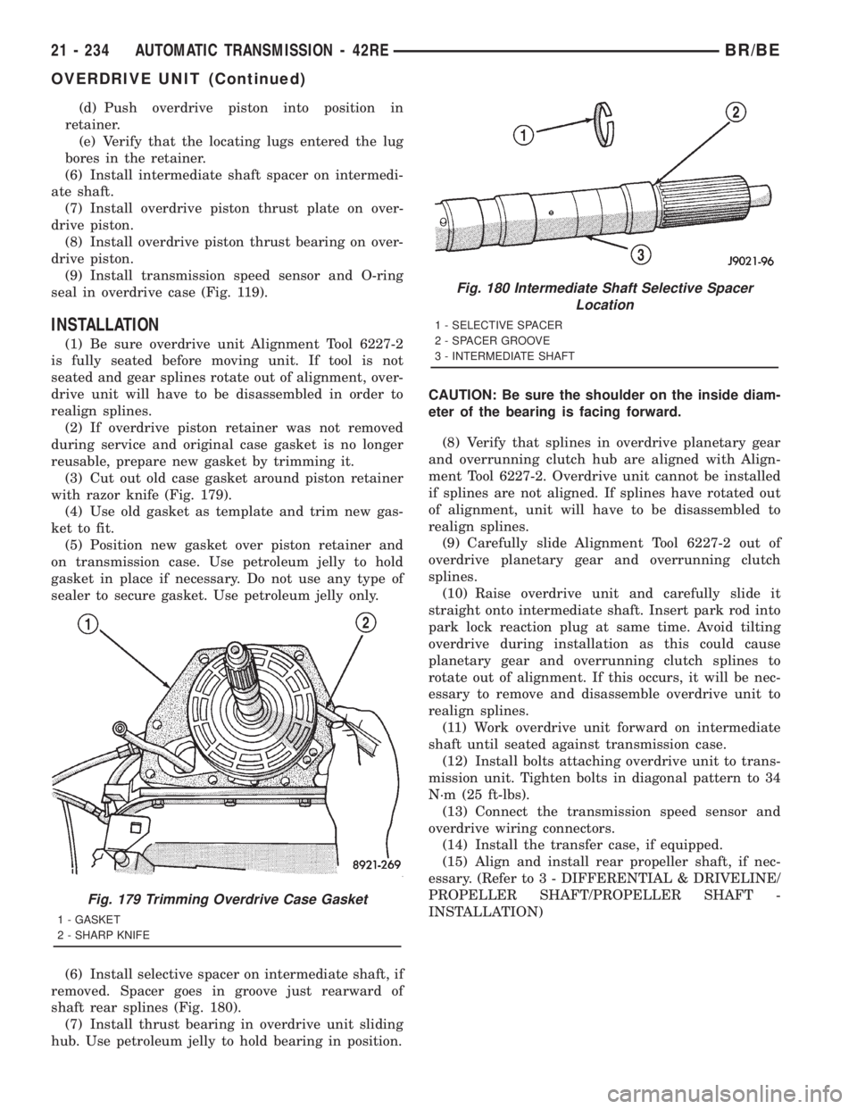
(3) Cut out old case gasket around piston retainer
with razor knife (Fig. 179).
(4) Use old gasket as template and trim new gas-
ket to fit.
(5) Position new gasket over piston retainer and
on transmission case. Use petroleum jelly to hold
gasket in place if necessary. Do not use any type of
sealer to secure gasket. Use petroleum jelly only.
(6) Install selective spacer on intermediate shaft, if
removed. Spacer goes in groove just rearward of
shaft rear splines (Fig. 180).
(7) Install thrust bearing in overdrive unit sliding
hub. Use petroleum jelly to hold bearing in position.CAUTION: Be sure the shoulder on the inside diam-
eter of the bearing is facing forward.
(8) Verify that splines in overdrive planetary gear
and overrunning clutch hub are aligned with Align-
ment Tool 6227-2. Overdrive unit cannot be installed
if splines are not aligned. If splines have rotated out
of alignment, unit will have to be disassembled to
realign splines.
(9) Carefully slide Alignment Tool 6227-2 out of
overdrive planetary gear and overrunning clutch
splines.
(10) Raise overdrive unit and carefully slide it
straight onto intermediate shaft. Insert park rod into
park lock reaction plug at same time. Avoid tilting
overdrive during installation as this could cause
planetary gear and overrunning clutch splines to
rotate out of alignment. If this occurs, it will be nec-
essary to remove and disassemble overdrive unit to
realign splines.
(11) Work overdrive unit forward on intermediate
shaft until seated against transmission case.
(12) Install bolts attaching overdrive unit to trans-
mission unit. Tighten bolts in diagonal pattern to 34
N´m (25 ft-lbs).
(13) Connect the transmission speed sensor and
overdrive wiring connectors.
(14) Install the transfer case, if equipped.
(15) Align and install rear propeller shaft, if nec-
essary. (Refer to 3 - DIFFERENTIAL & DRIVELINE/
PROPELLER SHAFT/PROPELLER SHAFT -
INSTALLATION)
Fig. 179 Trimming Overdrive Case Gasket
1 - GASKET
2 - SHARP KNIFE
Fig. 180 Intermediate Shaft Selective Spacer
Location
1 - SELECTIVE SPACER
2 - SPACER GROOVE
3 - INTERMEDIATE SHAFT
21 - 234 AUTOMATIC TRANSMISSION - 42REBR/BE
OVERDRIVE UNIT (Continued)
Page 1888 of 2889
plunger also contribute to the response speed possi-
ble by a particular solenoid design.
A solenoid can also be described by the method by
which it is controlled. Some of the possibilities
include variable force, pulse-width modulated, con-
stant ON, or duty cycle. The variable force and pulse-
width modulated versions utilize similar methods to
control the current flow through the solenoid to posi-
tion the solenoid plunger at a desired position some-
where between full ON and full OFF. The constant
ON and duty cycled versions control the voltage
across the solenoid to allow either full flow or no flow
through the solenoid's valve.
OPERATION
When an electrical current is applied to the sole-
noid coil, a magnetic field is created which produces
an attraction to the plunger, causing the plunger to
move and work against the spring pressure and the
load applied by the fluid the valve is controlling. The
plunger is normally directly attached to the valve
which it is to operate. When the current is removed
from the coil, the attraction is removed and the
plunger will return to its original position due to
spring pressure.
The plunger is made of a conductive material and
accomplishes this movement by providing a path for
the magnetic field to flow. By keeping the air gap
between the plunger and the coil to the minimum
necessary to allow free movement of the plunger, the
magnetic field is maximized.
SPEED SENSOR
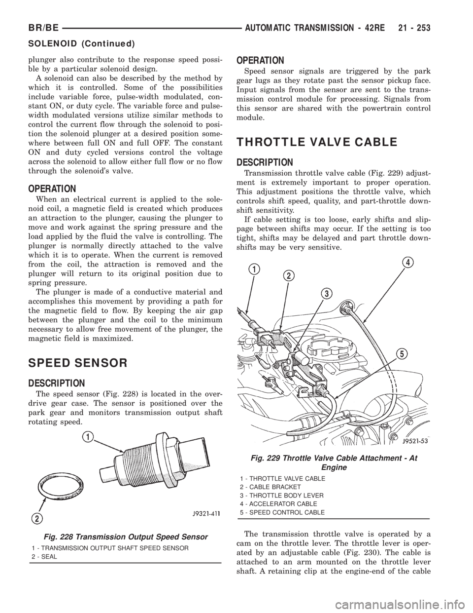
DESCRIPTION
The speed sensor (Fig. 228) is located in the over-
drive gear case. The sensor is positioned over the
park gear and monitors transmission output shaft
rotating speed.
OPERATION
Speed sensor signals are triggered by the park
gear lugs as they rotate past the sensor pickup face.
Input signals from the sensor are sent to the trans-
mission control module for processing. Signals from
this sensor are shared with the powertrain control
module.
THROTTLE VALVE CABLE
DESCRIPTION
Transmission throttle valve cable (Fig. 229) adjust-
ment is extremely important to proper operation.
This adjustment positions the throttle valve, which
controls shift speed, quality, and part-throttle down-
shift sensitivity.
If cable setting is too loose, early shifts and slip-
page between shifts may occur. If the setting is too
tight, shifts may be delayed and part throttle down-
shifts may be very sensitive.
The transmission throttle valve is operated by a
cam on the throttle lever. The throttle lever is oper-
ated by an adjustable cable (Fig. 230). The cable is
attached to an arm mounted on the throttle lever
shaft. A retaining clip at the engine-end of the cable
Fig. 228 Transmission Output Speed Sensor
1 - TRANSMISSION OUTPUT SHAFT SPEED SENSOR
2 - SEAL
Fig. 229 Throttle Valve Cable Attachment - At
Engine
1 - THROTTLE VALVE CABLE
2 - CABLE BRACKET
3 - THROTTLE BODY LEVER
4 - ACCELERATOR CABLE
5 - SPEED CONTROL CABLE
BR/BEAUTOMATIC TRANSMISSION - 42RE 21 - 253
SOLENOID (Continued)
Page 1897 of 2889
TORQUE CONVERTER
DRAINBACK VALVE
DESCRIPTION
The drainback valve is located in the transmission
cooler outlet (pressure) line.
OPERATION
The valve prevents fluid from draining from the
converter into the cooler and lines when the vehicle
is shut down for lengthy periods. Production valves
have a hose nipple at one end, while the opposite end
is threaded for a flare fitting. All valves have an
arrow (or similar mark) to indicate direction of flow
through the valve.
STANDARD PROCEDURE - TORQUE
CONVERTER DRAINBACK VALVE
The converter drainback check valve is located in
the cooler outlet (pressure) line near the radiator
tank. The valve prevents fluid drainback when the
vehicle is parked for lengthy periods. The valve check
ball is spring loaded and has an opening pressure of
approximately 2 psi.
The valve is serviced as an assembly; it is not
repairable. Do not clean the valve if restricted, or
contaminated by sludge, or debris. If the valve fails,
or if a transmission malfunction occurs that gener-
ates significant amounts of sludge and/or clutch par-
ticles and metal shavings, the valve must be
replaced.
The valve must be removed whenever the cooler
and lines are reverse flushed. The valve can be flow
tested when necessary. The procedure is exactly the
same as for flow testing a cooler.
If the valve is restricted, installed backwards, or in
the wrong line, it will cause an overheating condition
and possible transmission failure.
CAUTION: The drainback valve is a one-way flow
device. It must be properly oriented in terms of flow
direction for the cooler to function properly. The
valve must be installed in the pressure line. Other-
wise flow will be blocked and would cause an over-
heating condition and eventual transmission failure.
TRANSMISSION
TEMPERATURE SENSOR
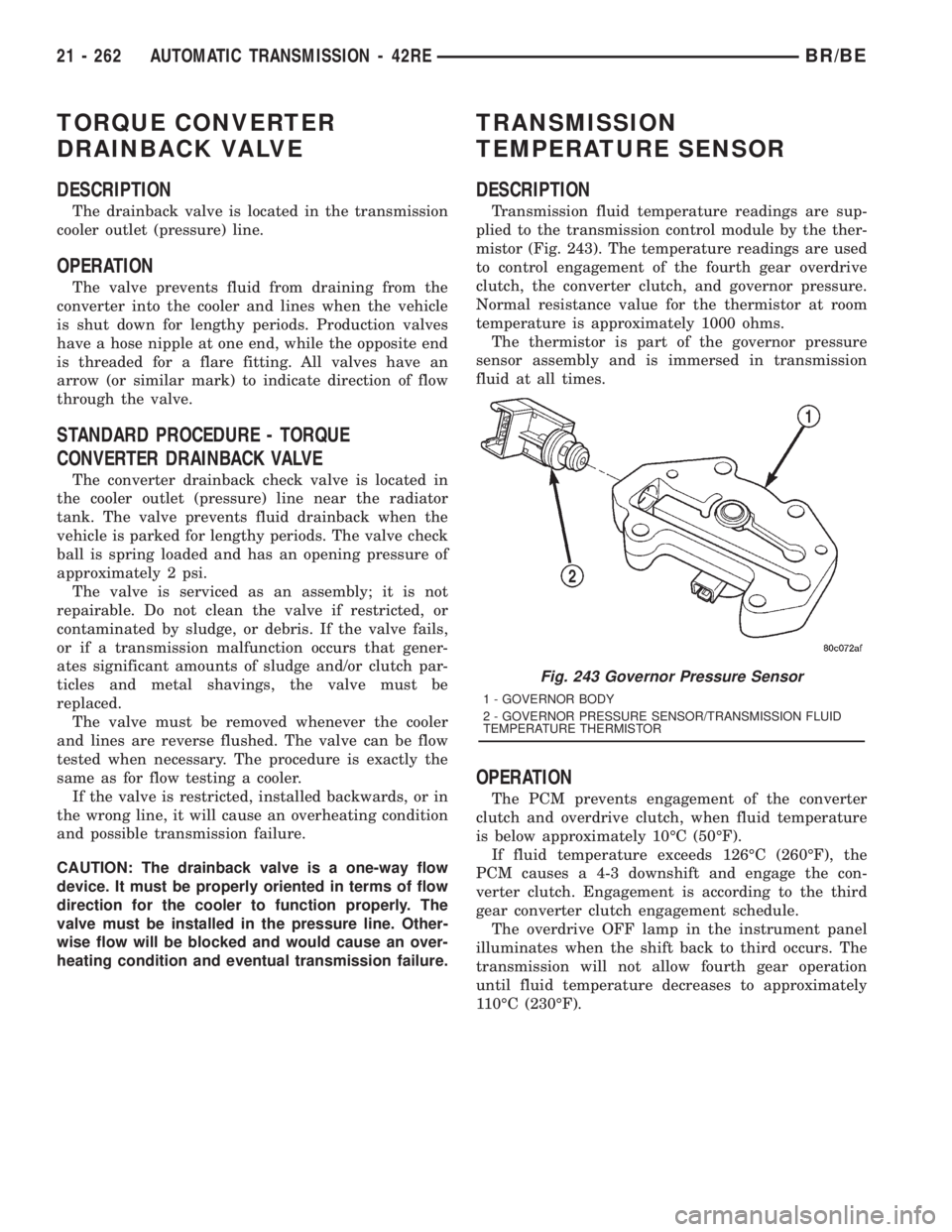
DESCRIPTION
Transmission fluid temperature readings are sup-
plied to the transmission control module by the ther-
mistor (Fig. 243). The temperature readings are used
to control engagement of the fourth gear overdrive
clutch, the converter clutch, and governor pressure.
Normal resistance value for the thermistor at room
temperature is approximately 1000 ohms.
The thermistor is part of the governor pressure
sensor assembly and is immersed in transmission
fluid at all times.
OPERATION
The PCM prevents engagement of the converter
clutch and overdrive clutch, when fluid temperature
is below approximately 10ÉC (50ÉF).
If fluid temperature exceeds 126ÉC (260ÉF), the
PCM causes a 4-3 downshift and engage the con-
verter clutch. Engagement is according to the third
gear converter clutch engagement schedule.
The overdrive OFF lamp in the instrument panel
illuminates when the shift back to third occurs. The
transmission will not allow fourth gear operation
until fluid temperature decreases to approximately
110ÉC (230ÉF).
Fig. 243 Governor Pressure Sensor
1 - GOVERNOR BODY
2 - GOVERNOR PRESSURE SENSOR/TRANSMISSION FLUID
TEMPERATURE THERMISTOR
21 - 262 AUTOMATIC TRANSMISSION - 42REBR/BE
Page 1916 of 2889
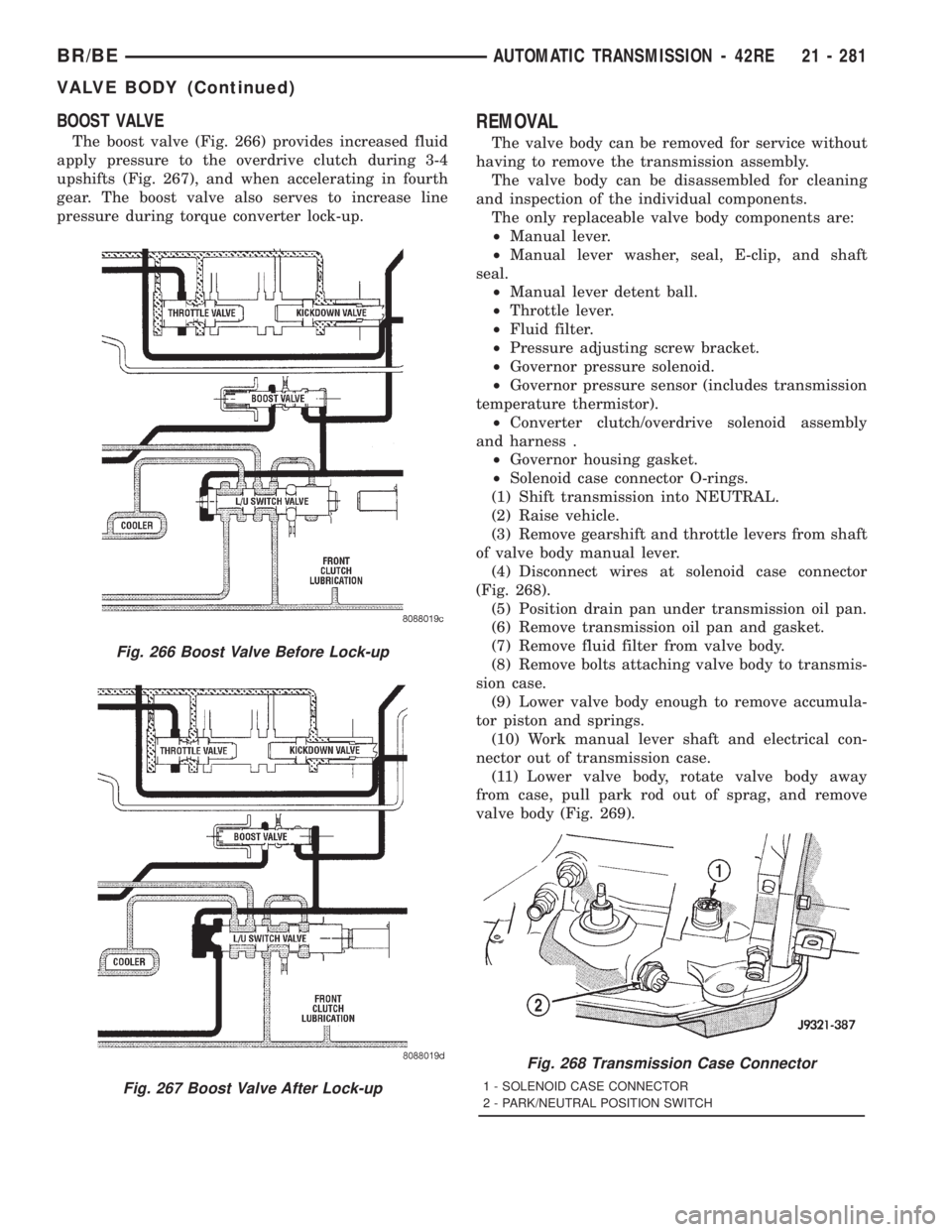
BOOST VALVE
The boost valve (Fig. 266) provides increased fluid
apply pressure to the overdrive clutch during 3-4
upshifts (Fig. 267), and when accelerating in fourth
gear. The boost valve also serves to increase line
pressure during torque converter lock-up.
REMOVAL
The valve body can be removed for service without
having to remove the transmission assembly.
The valve body can be disassembled for cleaning
and inspection of the individual components.
The only replaceable valve body components are:
²Manual lever.
²Manual lever washer, seal, E-clip, and shaft
seal.
²Manual lever detent ball.
²Throttle lever.
²Fluid filter.
²Pressure adjusting screw bracket.
²Governor pressure solenoid.
²Governor pressure sensor (includes transmission
temperature thermistor).
²Converter clutch/overdrive solenoid assembly
and harness .
²Governor housing gasket.
²Solenoid case connector O-rings.
(1) Shift transmission into NEUTRAL.
(2) Raise vehicle.
(3) Remove gearshift and throttle levers from shaft
of valve body manual lever.
(4) Disconnect wires at solenoid case connector
(Fig. 268).
(5) Position drain pan under transmission oil pan.
(6) Remove transmission oil pan and gasket.
(7) Remove fluid filter from valve body.
(8) Remove bolts attaching valve body to transmis-
sion case.
(9) Lower valve body enough to remove accumula-
tor piston and springs.
(10) Work manual lever shaft and electrical con-
nector out of transmission case.
(11) Lower valve body, rotate valve body away
from case, pull park rod out of sprag, and remove
valve body (Fig. 269).
Fig. 266 Boost Valve Before Lock-up
Fig. 267 Boost Valve After Lock-up
Fig. 268 Transmission Case Connector
1 - SOLENOID CASE CONNECTOR
2 - PARK/NEUTRAL POSITION SWITCH
BR/BEAUTOMATIC TRANSMISSION - 42RE 21 - 281
VALVE BODY (Continued)
Page 1917 of 2889
DISASSEMBLY
CAUTION: Do not clamp any valve body component
in a vise. This practice can damage the component
resulting in unsatisfactory operation after assembly
and installation. Do not use pliers to remove any of
the valves, plugs or springs and do not force any of
the components out or into place. The valves and
valve body housings will be damaged if force is
used. Tag or mark the valve body springs for refer-
ence as they are removed. Do not allow them to
become intermixed.
(1) Disconnect wires from governor pressure sen-
sor and solenoid.
(2) Remove screws attaching governor body and
retainer plate to transfer plate.
(3) Remove retainer plate, governor body and gas-
ket from transfer plate.
(4) Remove governor pressure sensor from gover-
nor body.
(5) Remove governor pressure solenoid by pulling
it straight out of bore in governor body. Remove and
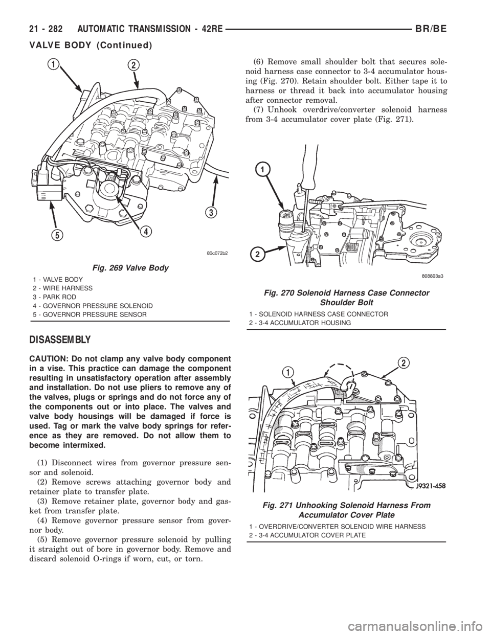
discard solenoid O-rings if worn, cut, or torn.(6) Remove small shoulder bolt that secures sole-
noid harness case connector to 3-4 accumulator hous-
ing (Fig. 270). Retain shoulder bolt. Either tape it to
harness or thread it back into accumulator housing
after connector removal.
(7) Unhook overdrive/converter solenoid harness
from 3-4 accumulator cover plate (Fig. 271).
Fig. 270 Solenoid Harness Case Connector
Shoulder Bolt
1 - SOLENOID HARNESS CASE CONNECTOR
2 - 3-4 ACCUMULATOR HOUSING
Fig. 271 Unhooking Solenoid Harness From
Accumulator Cover Plate
1 - OVERDRIVE/CONVERTER SOLENOID WIRE HARNESS
2 - 3-4 ACCUMULATOR COVER PLATE
Fig. 269 Valve Body
1 - VALVE BODY
2 - WIRE HARNESS
3 - PARK ROD
4 - GOVERNOR PRESSURE SOLENOID
5 - GOVERNOR PRESSURE SENSOR
21 - 282 AUTOMATIC TRANSMISSION - 42REBR/BE
VALVE BODY (Continued)
Page 1918 of 2889
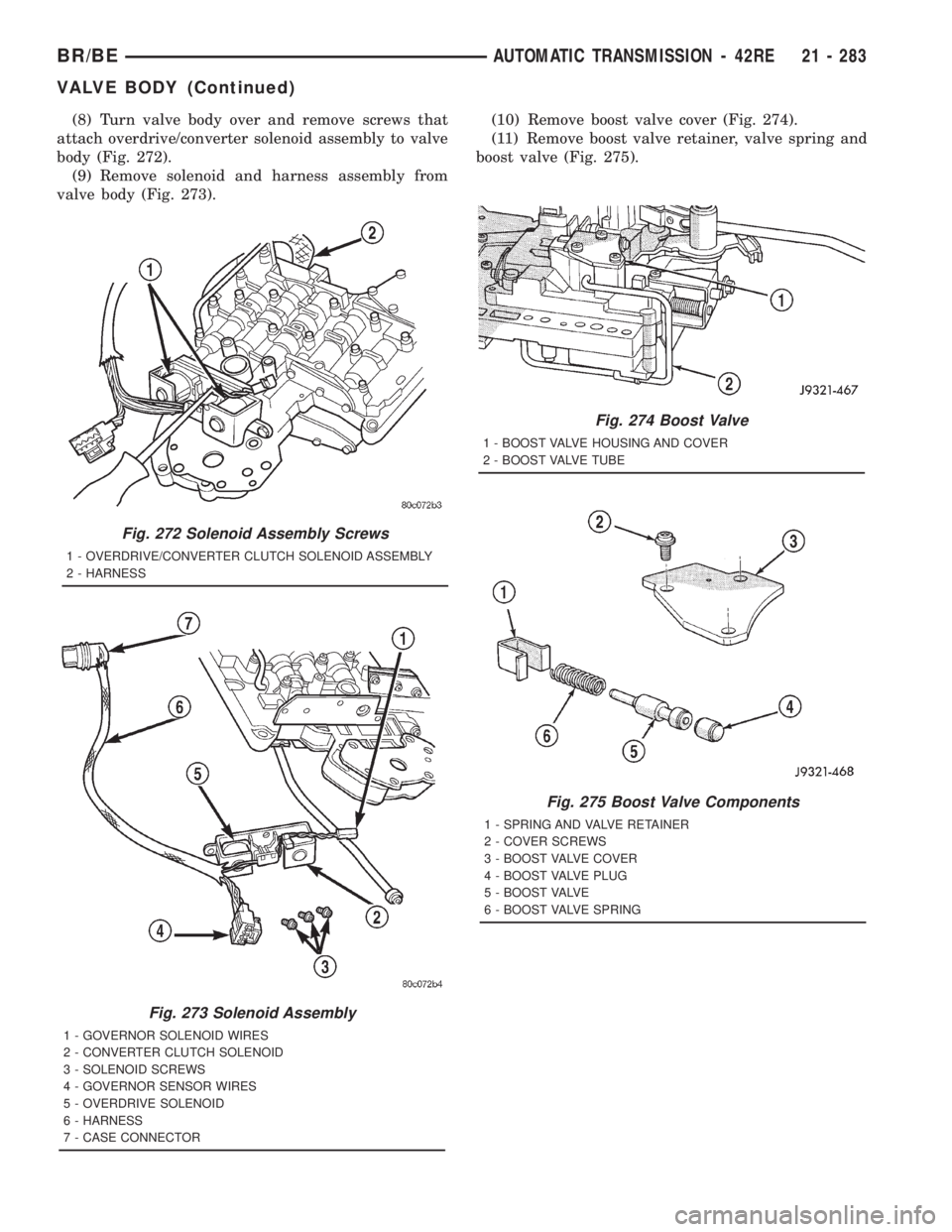
(8) Turn valve body over and remove screws that
attach overdrive/converter solenoid assembly to valve
body (Fig. 272).
(9) Remove solenoid and harness assembly from
valve body (Fig. 273).(10) Remove boost valve cover (Fig. 274).
(11) Remove boost valve retainer, valve spring and
boost valve (Fig. 275).
Fig. 272 Solenoid Assembly Screws
1 - OVERDRIVE/CONVERTER CLUTCH SOLENOID ASSEMBLY
2 - HARNESS
Fig. 273 Solenoid Assembly
1 - GOVERNOR SOLENOID WIRES
2 - CONVERTER CLUTCH SOLENOID
3 - SOLENOID SCREWS
4 - GOVERNOR SENSOR WIRES
5 - OVERDRIVE SOLENOID
6 - HARNESS
7 - CASE CONNECTOR
Fig. 274 Boost Valve
1 - BOOST VALVE HOUSING AND COVER
2 - BOOST VALVE TUBE
Fig. 275 Boost Valve Components
1 - SPRING AND VALVE RETAINER
2 - COVER SCREWS
3 - BOOST VALVE COVER
4 - BOOST VALVE PLUG
5 - BOOST VALVE
6 - BOOST VALVE SPRING
BR/BEAUTOMATIC TRANSMISSION - 42RE 21 - 283
VALVE BODY (Continued)
Page 1928 of 2889
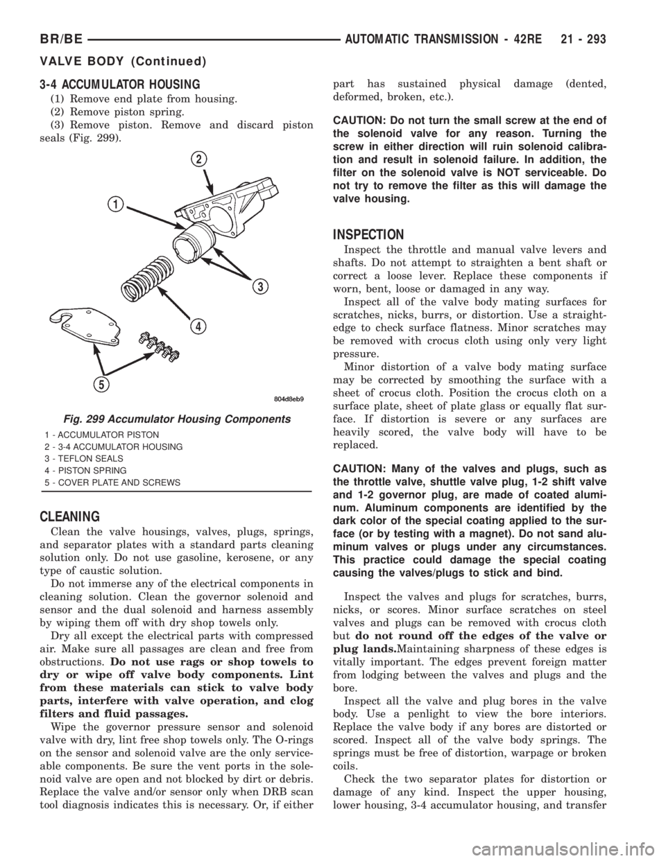
3-4 ACCUMULATOR HOUSING
(1) Remove end plate from housing.
(2) Remove piston spring.
(3) Remove piston. Remove and discard piston
seals (Fig. 299).
CLEANING
Clean the valve housings, valves, plugs, springs,
and separator plates with a standard parts cleaning
solution only. Do not use gasoline, kerosene, or any
type of caustic solution.
Do not immerse any of the electrical components in
cleaning solution. Clean the governor solenoid and
sensor and the dual solenoid and harness assembly
by wiping them off with dry shop towels only.
Dry all except the electrical parts with compressed
air. Make sure all passages are clean and free from
obstructions.Do not use rags or shop towels to
dry or wipe off valve body components. Lint
from these materials can stick to valve body
parts, interfere with valve operation, and clog
filters and fluid passages.
Wipe the governor pressure sensor and solenoid
valve with dry, lint free shop towels only. The O-rings
on the sensor and solenoid valve are the only service-
able components. Be sure the vent ports in the sole-
noid valve are open and not blocked by dirt or debris.
Replace the valve and/or sensor only when DRB scan
tool diagnosis indicates this is necessary. Or, if eitherpart has sustained physical damage (dented,
deformed, broken, etc.).
CAUTION: Do not turn the small screw at the end of
the solenoid valve for any reason. Turning the
screw in either direction will ruin solenoid calibra-
tion and result in solenoid failure. In addition, the
filter on the solenoid valve is NOT serviceable. Do
not try to remove the filter as this will damage the
valve housing.
INSPECTION
Inspect the throttle and manual valve levers and
shafts. Do not attempt to straighten a bent shaft or
correct a loose lever. Replace these components if
worn, bent, loose or damaged in any way.
Inspect all of the valve body mating surfaces for
scratches, nicks, burrs, or distortion. Use a straight-
edge to check surface flatness. Minor scratches may
be removed with crocus cloth using only very light
pressure.
Minor distortion of a valve body mating surface
may be corrected by smoothing the surface with a
sheet of crocus cloth. Position the crocus cloth on a
surface plate, sheet of plate glass or equally flat sur-
face. If distortion is severe or any surfaces are
heavily scored, the valve body will have to be
replaced.
CAUTION: Many of the valves and plugs, such as
the throttle valve, shuttle valve plug, 1-2 shift valve
and 1-2 governor plug, are made of coated alumi-
num. Aluminum components are identified by the
dark color of the special coating applied to the sur-
face (or by testing with a magnet). Do not sand alu-
minum valves or plugs under any circumstances.
This practice could damage the special coating
causing the valves/plugs to stick and bind.
Inspect the valves and plugs for scratches, burrs,
nicks, or scores. Minor surface scratches on steel
valves and plugs can be removed with crocus cloth
butdo not round off the edges of the valve or
plug lands.Maintaining sharpness of these edges is
vitally important. The edges prevent foreign matter
from lodging between the valves and plugs and the
bore.
Inspect all the valve and plug bores in the valve
body. Use a penlight to view the bore interiors.
Replace the valve body if any bores are distorted or
scored. Inspect all of the valve body springs. The
springs must be free of distortion, warpage or broken
coils.
Check the two separator plates for distortion or
damage of any kind. Inspect the upper housing,
lower housing, 3-4 accumulator housing, and transfer
Fig. 299 Accumulator Housing Components
1 - ACCUMULATOR PISTON
2 - 3-4 ACCUMULATOR HOUSING
3 - TEFLON SEALS
4 - PISTON SPRING
5 - COVER PLATE AND SCREWS
BR/BEAUTOMATIC TRANSMISSION - 42RE 21 - 293
VALVE BODY (Continued)