AUX DODGE RAM 2001 Service Owner's Manual
[x] Cancel search | Manufacturer: DODGE, Model Year: 2001, Model line: RAM, Model: DODGE RAM 2001Pages: 2889, PDF Size: 68.07 MB
Page 1512 of 2889
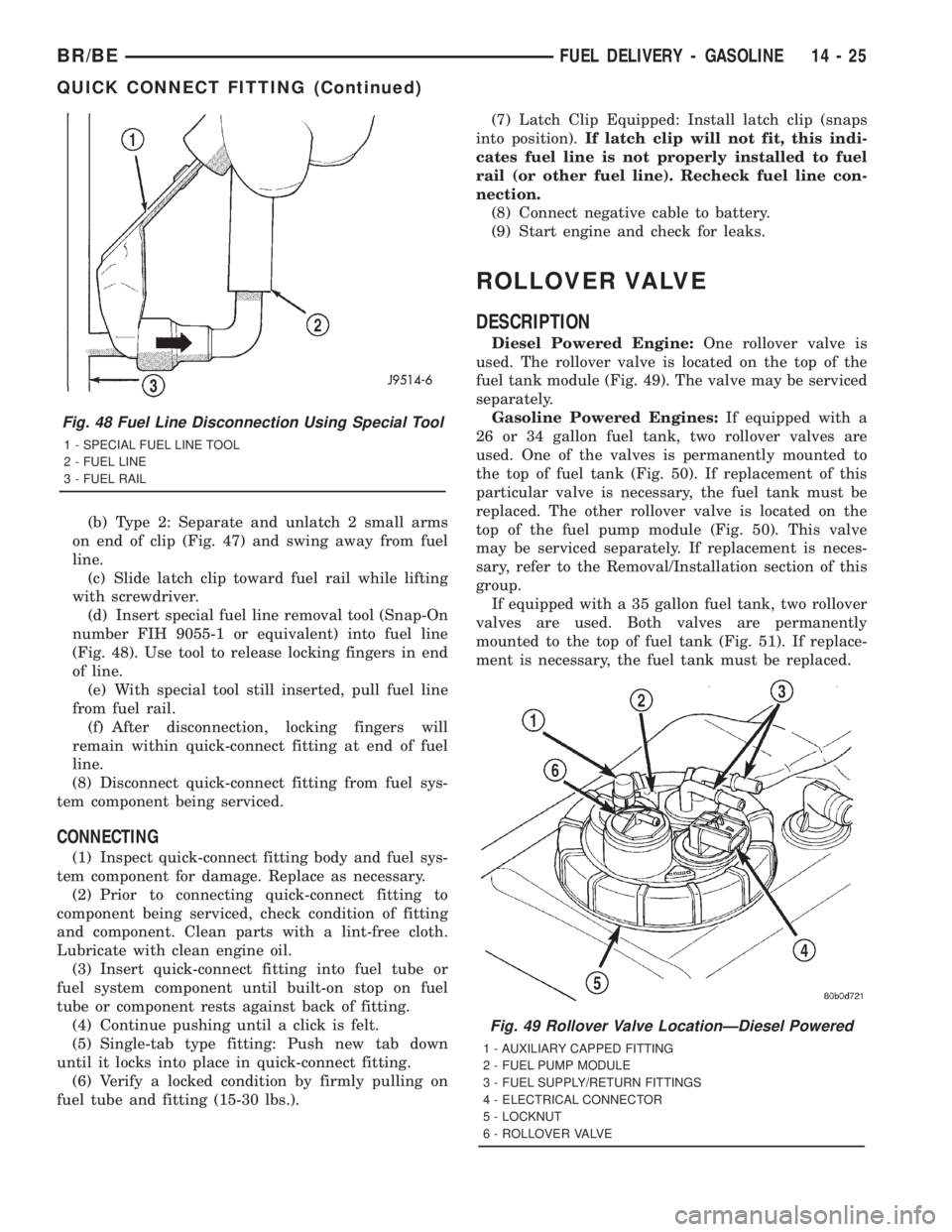
(b) Type 2: Separate and unlatch 2 small arms
on end of clip (Fig. 47) and swing away from fuel
line.
(c) Slide latch clip toward fuel rail while lifting
with screwdriver.
(d) Insert special fuel line removal tool (Snap-On
number FIH 9055-1 or equivalent) into fuel line
(Fig. 48). Use tool to release locking fingers in end
of line.
(e) With special tool still inserted, pull fuel line
from fuel rail.
(f) After disconnection, locking fingers will
remain within quick-connect fitting at end of fuel
line.
(8) Disconnect quick-connect fitting from fuel sys-
tem component being serviced.
CONNECTING
(1) Inspect quick-connect fitting body and fuel sys-
tem component for damage. Replace as necessary.
(2) Prior to connecting quick-connect fitting to
component being serviced, check condition of fitting
and component. Clean parts with a lint-free cloth.
Lubricate with clean engine oil.
(3) Insert quick-connect fitting into fuel tube or
fuel system component until built-on stop on fuel
tube or component rests against back of fitting.
(4) Continue pushing until a click is felt.
(5) Single-tab type fitting: Push new tab down
until it locks into place in quick-connect fitting.
(6) Verify a locked condition by firmly pulling on
fuel tube and fitting (15-30 lbs.).(7) Latch Clip Equipped: Install latch clip (snaps
into position).If latch clip will not fit, this indi-
cates fuel line is not properly installed to fuel
rail (or other fuel line). Recheck fuel line con-
nection.
(8) Connect negative cable to battery.
(9) Start engine and check for leaks.
ROLLOVER VALVE
DESCRIPTION
Diesel Powered Engine:One rollover valve is
used. The rollover valve is located on the top of the
fuel tank module (Fig. 49). The valve may be serviced
separately.
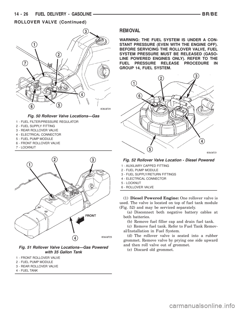
Gasoline Powered Engines:If equipped with a
26 or 34 gallon fuel tank, two rollover valves are
used. One of the valves is permanently mounted to
the top of fuel tank (Fig. 50). If replacement of this
particular valve is necessary, the fuel tank must be
replaced. The other rollover valve is located on the
top of the fuel pump module (Fig. 50). This valve
may be serviced separately. If replacement is neces-
sary, refer to the Removal/Installation section of this
group.
If equipped with a 35 gallon fuel tank, two rollover
valves are used. Both valves are permanently
mounted to the top of fuel tank (Fig. 51). If replace-
ment is necessary, the fuel tank must be replaced.
Fig. 48 Fuel Line Disconnection Using Special Tool
1 - SPECIAL FUEL LINE TOOL
2 - FUEL LINE
3 - FUEL RAIL
Fig. 49 Rollover Valve LocationÐDiesel Powered
1 - AUXILIARY CAPPED FITTING
2 - FUEL PUMP MODULE
3 - FUEL SUPPLY/RETURN FITTINGS
4 - ELECTRICAL CONNECTOR
5 - LOCKNUT
6 - ROLLOVER VALVE
BR/BEFUEL DELIVERY - GASOLINE 14 - 25
QUICK CONNECT FITTING (Continued)
Page 1513 of 2889
REMOVAL
WARNING: THE FUEL SYSTEM IS UNDER A CON-
STANT PRESSURE (EVEN WITH THE ENGINE OFF).
BEFORE SERVICING THE ROLLOVER VALVE, FUEL
SYSTEM PRESSURE MUST BE RELEASED (GASO-
LINE POWERED ENGINES ONLY). REFER TO THE
FUEL PRESSURE RELEASE PROCEDURE IN
GROUP 14, FUEL SYSTEM.
(1)Diesel Powered Engine:One rollover valve is
used. The valve is located on top of fuel tank module
(Fig. 52) and may be serviced separately.
(a) Disconnect both negative battery cables at
both batteries.
(b) Remove fuel filler cap and drain fuel tank.
(c) Remove fuel tank. Refer to Fuel Tank Remov-
al/Installation in Fuel System.
(d) The rollover valve is seated into a rubber
grommet. Remove valve by prying one side upward
and then roll valve out of grommet.
(e) Discard old grommet.
Fig. 50 Rollover Valve LocationsÐGas
1 - FUEL FILTER/PRESSURE REGULATOR
2 - FUEL SUPPLY FITTING
3 - REAR ROLLOVER VALVE
4 - ELECTRICAL CONNECTOR
5 - FUEL PUMP MODULE
6 - FRONT ROLLOVER VALVE
7 - LOCKNUT
Fig. 51 Rollover Valve LocationsÐGas Powered
with 35 Gallon Tank
1 - FRONT ROLLOVER VALVE
2 - FUEL PUMP MODULE
3 - REAR ROLLOVER VALVE
4 - FUEL TANK
Fig. 52 Rollover Valve Location - Diesel Powered
1 - AUXILIARY CAPPED FITTING
2 - FUEL PUMP MODULE
3 - FUEL SUPPLY/RETURN FITTINGS
4 - ELECTRICAL CONNECTOR
5 - LOCKNUT
6 - ROLLOVER VALVE
14 - 26 FUEL DELIVERY - GASOLINEBR/BE
ROLLOVER VALVE (Continued)
Page 1565 of 2889
(3) Installrearinjection line bundle beginning
with cylinder head (fuel injector) connections, fol-
lowed by injection pump connections. Tighten all fit-
tings finger tight.
(4) Tighten fittings at fuel injector ends for cylin-
ders number 6 and 5 to 38 N´m (28 ft. lbs.) torque.
Do not tighten number 3 line at this time. It
will be tightened during bleeding procedure.
(5) Tighten 3 fittings at fuel injection pump ends
to 24 N´m (18 ft. lbs.) torque.
(6) Installfrontinjection line bundle beginning
with cylinder head (fuel injector) connections, fol-
lowed by injection pump connections. Tighten all fit-
tings finger tight.
(7) Tighten fitting at fuel injector end for cylinder
number 2 to 38 N´m (28 ft. lbs.) torque.Do not
tighten lines number 1 or 4 at this time. They
will be tightened during bleeding procedure.
(8) Tighten remaining 3 fittings at fuel injection
pump ends to 24 N´m (18 ft. lbs.) torque.
(9) Install fuel line support bracket bolts to intake
manifold and tighten to 24 N´m (18 ft. lbs.) torque.
CAUTION: Be sure fuel lines are not contacting
each other or any other component. Noise will
result.
(10) Install engine lifting bracket at rear of intake
manifold. Tighten 2 bolts to 77 N´m (57 ft. lbs.)
torque.
(11) Install cable bracket housing/cable assembly
and tighten 3 mounting bolts to 24 N´m (18 ft. lbs.)
torque.
(12) Clean any old gasket material below and
above intake manifold air heater element block. Also
clean mating areas at intake manifold and air intake
housing.
(13) Using new gaskets, position intake manifold
air heater element block to engine.
(14) Install air intake housing and position ground
cable. Install 4 mounting bolts and tighten to 24 N´m
(18 ft. lbs.) torque.
(15) Install air tube (intake manifold-to-charge air
cooler) (Fig. 41). Tighten clamps to 8 N´m (72 in. lbs.)
torque.
(16) Install engine oil dipstick tube support mount-
ing bolt and tighten to 24 N´m (18 ft. lbs.) torque.
(17) Install engine oil dipstick to engine.
(18) Connect 2 electrical cables to cable mounting
studs.
(19) Connect electrical connector to bottom of
APPS by pushing connector upward until it snaps
into position.
(20) Connect wiring harness (clip) at bottom of
Accelerator Pedal Position Sensor (APPS) mounting
bracket (Fig. 40).(21) Connect front wiring clip (Fig. 41) to cable
bracket housing.
(22) Install cable cover (Fig. 39).
(23) Connect both negative battery cables to both
batteries.
(24) Bleed air from fuel system. Do this at fuel
injector ends of lines. Use cylinders numbers 1, 3 and
4 for bleeding . (Refer to 14 - FUEL SYSTEM/FUEL
DELIVERY - STANDARD PROCEDURE). After
bleeding, tighten fittings to 38 N´m (28 ft. lbs.)
torque.
(25) Check lines/fittings for leaks.
FUEL TANK
DESCRIPTION - DIESEL FUEL TANK
The fuel tank is similar to the tank used with gas-
oline powered models. The tank is equipped with a
separate fuel return line and a different fuel tank
module for diesel powered models. A fuel tank
mounted, electric fuel pump is not used with diesel
powered models. Refer to Fuel Tank Module for addi-
tional information.
For removal and installation procedures, refer to
Fuel Tank - Gasoline Engines.
FUEL TANK MODULE
DESCRIPTION
An electric fuel pump isnot usedin the fuel tank
module for diesel powered engines. Fuel is supplied
by the engine mounted fuel transfer pump and the
fuel injection pump.
The fuel tank module is installed in the top of the
fuel tank (Fig. 48). The fuel tank module (Fig. 48)
contains the following components:
²Fuel reservoir
²A separate in-tank fuel filter
²Rollover valve
²Fuel gauge sending unit (fuel level sensor)
²Fuel supply line connection
²Fuel return line connection
²Auxiliary non-pressurized fuel supply fitting
OPERATION
Refer to Fuel Gauge Sending Unit.
REMOVAL
(1) Drain and remove fuel tank. Refer to Fuel
Tank Removal/Installation.
(2) Thoroughly clean area around tank module at
top of tank.
14 - 78 FUEL DELIVERY - DIESELBR/BE
FUEL LINES (Continued)
Page 1566 of 2889
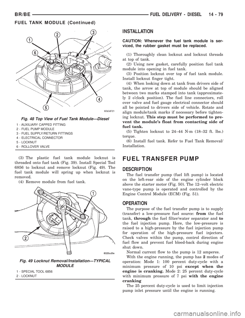
(3) The plastic fuel tank module locknut is
threaded onto fuel tank (Fig. 39). Install Special Tool
6856 to locknut and remove locknut (Fig. 49). The
fuel tank module will spring up when locknut is
removed.
(4) Remove module from fuel tank.
INSTALLATION
CAUTION: Whenever the fuel tank module is ser-
viced, the rubber gasket must be replaced.
(1) Thoroughly clean locknut and locknut threads
at top of tank.
(2) Using new gasket, carefully position fuel tank
module into opening in fuel tank.
(3) Position locknut over top of fuel tank module.
Install locknut finger tight.
(4) When looking down at tank from drivers side of
tank, the arrow at top of module should be aligned
between two marks stamped into tank (approximate-
ly 2 o'clock position). The fuel line connectors, roll
over valve and fuel gauge electrical connector should
all be pointed to drivers side of vehicle. Rotate and
align module/tank marks if necessary before tighten-
ing locknut.This step must be performed to pre-
vent the module's float from contacting side of
fuel tank.
(5) Tighten locknut to 24±44 N´m (18±32 ft. lbs.)
torque.
(6) Install fuel tank. Refer to Fuel Tank Removal/
Installation.
FUEL TRANSFER PUMP
DESCRIPTION
The fuel transfer pump (fuel lift pump) is located
on the left-rear side of the engine cylinder block
above the starter motor (Fig. 50). The 12±volt electric
vane-type pump is operated and controlled by the
Engine Control Module (ECM) (Fig. 51).
OPERATION
The purpose of the fuel transfer pump is to supply
(transfer) a low-pressure fuel source:fromthe fuel
tank,throughthe fuel filter/water separator andto
the fuel injection pump. Here, the low-pressure is
raised to a high-pressure by the fuel injection pump
for operation of the high-pressure fuel injectors.
Check valves within the pump, control direction of
fuel flow and prevent fuel bleed-back during engine
shut down.
Normal current flow to the pump is 12 amperes.
With the engine running, the pump has2modes of
operation: Mode 1: 100 percent duty-cycle with a
minimum pressure of 10 psiexcept when the
engine is cranking.Mode 2: 25 percent duty-cycle
with minimum pressure of 7 psiwith the engine
cranking
The 25 percent duty-cycle is used to limit injection
pump inlet pressure until the engine is running.
Fig. 48 Top View of Fuel Tank ModuleÐDiesel
1 - AUXILIARY CAPPED FITTING
2 - FUEL PUMP MODULE
3 - FUEL SUPPLY/RETURN FITTINGS
4 - ELECTRICAL CONNECTOR
5 - LOCKNUT
6 - ROLLOVER VALVE
Fig. 49 Locknut Removal/InstallationÐTYPICAL
MODULE
1 - SPECIAL TOOL 6856
2 - LOCKNUT
BR/BEFUEL DELIVERY - DIESEL 14 - 79
FUEL TANK MODULE (Continued)
Page 1834 of 2889
FLUID AND FILTER
DIAGNOSIS AND TESTING - EFFECTS OF
INCORRECT FLUID LEVEL
A low fluid level allows the pump to take in air
along with the fluid. Air in the fluid will cause fluid
pressures to be low and develop slower than normal.
If the transmission is overfilled, the gears churn the
fluid into foam. This aerates the fluid and causing
the same conditions occurring with a low level. In
either case, air bubbles cause fluid overheating, oxi-
dation and varnish buildup which interferes with
valve and clutch operation. Foaming also causes fluid
expansion which can result in fluid overflow from the
transmission vent or fill tube. Fluid overflow can eas-
ily be mistaken for a leak if inspection is not careful.
DIAGNOSIS AND TESTING - CAUSES OF
BURNT FLUID
Burnt, discolored fluid is a result of overheating
which has two primary causes.
(1) A result of restricted fluid flow through the
main and/or auxiliary cooler. This condition is usu-
ally the result of a faulty or improperly installed
drainback valve, a damaged main cooler, or severe
restrictions in the coolers and lines caused by debris
or kinked lines.
(2) Heavy duty operation with a vehicle not prop-
erly equipped for this type of operation. Trailer tow-
ing or similar high load operation will overheat the
transmission fluid if the vehicle is improperly
equipped. Such vehicles should have an auxiliary
transmission fluid cooler, a heavy duty cooling sys-
tem, and the engine/axle ratio combination needed to
handle heavy loads.
DIAGNOSIS AND TESTING - FLUID
CONTAMINATION
Transmission fluid contamination is generally a
result of:
²adding incorrect fluid
²failure to clean dipstick and fill tube when
checking level
²engine coolant entering the fluid
²internal failure that generates debris
²
overheat that generates sludge (fluid breakdown)
²failure to reverse flush cooler and lines after repair
²failure to replace contaminated converter after
repair
The use of non-recommended fluids can result in
transmission failure. The usual results are erratic
shifts, slippage, abnormal wear and eventual failure
due to fluid breakdown and sludge formation. Avoid
this condition by using recommended fluids only.
The dipstick cap and fill tube should be wiped clean
before checking fluid level. Dirt, grease and other for-
eign material on the cap and tube could fall into the
tube if not removed beforehand. Take the time to wipe
the cap and tube clean before withdrawing the dipstick.
Engine coolant in the transmission fluid is gener-
ally caused by a cooler malfunction. The only remedy
is to replace the radiator as the cooler in the radiator
is not a serviceable part. If coolant has circulated
through the transmission, an overhaul is necessary.
The transmission cooler and lines should be
reverse flushed whenever a malfunction generates
sludge and/or debris. The torque converter should
also be replaced at the same time.
Failure to flush the cooler and lines will result in
recontamination. Flushing applies to auxiliary coolers
as well. The torque converter should also be replaced
whenever a failure generates sludge and debris. This is
necessary because normal converter flushing procedures
will not remove all contaminants.
STANDARD PROCEDURE - FLUID LEVEL
CHECK
Low fluid level can cause a variety of conditions
because it allows the pump to take in air along with
the fluid. As in any hydraulic system, air bubbles
make the fluid spongy, therefore, pressures will be
low and build up slowly.
Improper filling can also raise the fluid level too
high. When the transmssion has too much fluid, the
geartrain churns up foam and cause the same condi-
tions which occur with a low fluid level.
In either case, air bubbles can cause overheating
and/or fluid oxidation, and varnishing. This can inter-
fere with normal valve, clutch, and accumulator opera-
tion. Foaming can also result in fluid escaping from the
transmission vent where it may be mistaken for a leak.
Along with fluid level, it is important to check the
condition of the fluid. When the fluid smells burned,
and is contaminated with metal or friction material
particles, a complete transmission recondition is
needed. Be sure to examine the fluid on the dipstick
closely. If there is any doubt about its condition,
drain out a sample for a double check.
After the fluid has been checked, seat the dipstick
fully to seal out water and dirt.
The transmission has a dipstick to check oil level.
It is located on the right side of the engine. Be sure
to wipe all dirt from dipstick handle before removing.
Fluid level is checked with the engine running at curb
idle speed, the transmission in NEUTRAL and the trans-
mission fluid at normal operating temperature.The
engine should be running at idle speed for at least
one minute, with the vehicle on level ground.
The transmission fluid level can be checked two
ways.
BR/BEAUTOMATIC TRANSMISSION - 42RE 21 - 199
Page 2005 of 2889
FLUID AND FILTER
DIAGNOSIS AND TESTING - EFFECTS OF
INCORRECT FLUID LEVEL
A low fluid level allows the pump to take in air
along with the fluid. Air in the fluid will cause fluid
pressures to be low and develop slower than normal.
If the transmission is overfilled, the gears churn the
fluid into foam. This aerates the fluid and causing
the same conditions occurring with a low level. In
either case, air bubbles cause fluid overheating, oxi-
dation and varnish buildup which interferes with
valve and clutch operation. Foaming also causes fluid
expansion which can result in fluid overflow from the
transmission vent or fill tube. Fluid overflow can eas-
ily be mistaken for a leak if inspection is not careful.
DIAGNOSIS AND TESTING - CAUSES OF
BURNT FLUID
Burnt, discolored fluid is a result of overheating
which has two primary causes.
(1)
A result of restricted fluid flow through the main
and/or auxiliary cooler. This condition is usually the
result of a faulty or improperly installed drainback
valve, a damaged main cooler, or severe restrictions in
the coolers and lines caused by debris or kinked lines.
(2) Heavy duty operation with a vehicle not prop-
erly equipped for this type of operation. Trailer tow-
ing or similar high load operation will overheat the
transmission fluid if the vehicle is improperly
equipped. Such vehicles should have an auxiliary
transmission fluid cooler, a heavy duty cooling sys-
tem, and the engine/axle ratio combination needed to
handle heavy loads.
DIAGNOSIS AND TESTING - FLUID
CONTAMINATION
Transmission fluid contamination is generally a
result of:
²adding incorrect fluid
²failure to clean dipstick and fill tube when
checking level
²engine coolant entering the fluid
²internal failure that generates debris
²
overheat that generates sludge (fluid breakdown)
²failure to reverse flush cooler and lines after repair
²failure to replace contaminated converter after
repair
The use of non-recommended fluids can result in
transmission failure. The usual results are erratic
shifts, slippage, abnormal wear and eventual failure
due to fluid breakdown and sludge formation. Avoid
this condition by using recommended fluids only.
The dipstick cap and fill tube should be wiped
clean before checking fluid level. Dirt, grease andother foreign material on the cap and tube could fall
into the tube if not removed beforehand. Take the
time to wipe the cap and tube clean before withdraw-
ing the dipstick.
Engine coolant in the transmission fluid is gener-
ally caused by a cooler malfunction. The only remedy
is to replace the radiator as the cooler in the radiator
is not a serviceable part. If coolant has circulated
through the transmission, an overhaul is necessary.
The transmission cooler and lines should be
reverse flushed whenever a malfunction generates
sludge and/or debris. The torque converter should
also be replaced at the same time.
Failure to flush the cooler and lines will result in
recontamination. Flushing applies to auxiliary coolers
as well. The torque converter should also be replaced
whenever a failure generates sludge and debris. This is
necessary because normal converter flushing procedures
will not remove all contaminants.
STANDARD PROCEDURE - FLUID LEVEL
CHECK
Low fluid level can cause a variety of conditions
because it allows the pump to take in air along with
the fluid. As in any hydraulic system, air bubbles
make the fluid spongy, therefore, pressures will be
low and build up slowly.
Improper filling can also raise the fluid level too
high. When the transmssion has too much fluid, the
geartrain churns up foam and cause the same condi-
tions which occur with a low fluid level.
In either case, air bubbles can cause overheating
and/or fluid oxidation, and varnishing. This can
interfere with normal valve, clutch, and accumulator
operation. Foaming can also result in fluid escaping
from the transmission vent where it may be mis-
taken for a leak.
Along with fluid level, it is important to check the
condition of the fluid. When the fluid smells burned,
and is contaminated with metal or friction material
particles, a complete transmission recondition is
needed. Be sure to examine the fluid on the dipstick
closely. If there is any doubt about its condition,
drain out a sample for a double check.
After the fluid has been checked, seat the dipstick
fully to seal out water and dirt.
The transmission has a dipstick to check oil level.
It is located on the right side of the engine. Be sure
to wipe all dirt from dipstick handle before removing.
Fluid level is checked with the engine running at
curb idle speed, the transmission in NEUTRAL and the
transmission fluid at normal operating temperature.
The engine should be running at idle speed for at
least one minute, with the vehicle on level
ground.
The transmission fluid level can be checked two ways.
21 - 370 AUTOMATIC TRANSMISSION - 44REBR/BE
Page 2180 of 2889
FLUID AND FILTER
DIAGNOSIS AND TESTING - EFFECTS OF
INCORRECT FLUID LEVEL
A low fluid level allows the pump to take in air
along with the fluid. Air in the fluid will cause fluid
pressures to be low and develop slower than normal.
If the transmission is overfilled, the gears churn the
fluid into foam. This aerates the fluid and causing
the same conditions occurring with a low level. In
either case, air bubbles cause fluid overheating, oxi-
dation and varnish buildup which interferes with
valve and clutch operation. Foaming also causes fluid
expansion which can result in fluid overflow from the
transmission vent or fill tube. Fluid overflow can eas-
ily be mistaken for a leak if inspection is not careful.
DIAGNOSIS AND TESTING - CAUSES OF
BURNT FLUID
Burnt, discolored fluid is a result of overheating
which has two primary causes.
(1)
A result of restricted fluid flow through the main
and/or auxiliary cooler. This condition is usually the
result of a faulty or improperly installed drainback
valve, a damaged main cooler, or severe restrictions in
the coolers and lines caused by debris or kinked lines.
(2) Heavy duty operation with a vehicle not prop-
erly equipped for this type of operation. Trailer tow-
ing or similar high load operation will overheat the
transmission fluid if the vehicle is improperly
equipped. Such vehicles should have an auxiliary
transmission fluid cooler, a heavy duty cooling sys-
tem, and the engine/axle ratio combination needed to
handle heavy loads.
DIAGNOSIS AND TESTING - FLUID
CONTAMINATION
Transmission fluid contamination is generally a
result of:
²adding incorrect fluid
²failure to clean dipstick and fill tube when
checking level
²engine coolant entering the fluid
²internal failure that generates debris
²
overheat that generates sludge (fluid breakdown)
²failure to reverse flush cooler and lines after repair
²failure to replace contaminated converter after
repair
The use of non-recommended fluids can result in
transmission failure. The usual results are erratic
shifts, slippage, abnormal wear and eventual failure
due to fluid breakdown and sludge formation. Avoid
this condition by using recommended fluids only.
The dipstick cap and fill tube should be wiped
clean before checking fluid level. Dirt, grease andother foreign material on the cap and tube could fall
into the tube if not removed beforehand. Take the
time to wipe the cap and tube clean before withdraw-
ing the dipstick.
Engine coolant in the transmission fluid is gener-
ally caused by a cooler malfunction. The only remedy
is to replace the radiator as the cooler in the radiator
is not a serviceable part. If coolant has circulated
through the transmission, an overhaul is necessary.
The transmission cooler and lines should be
reverse flushed whenever a malfunction generates
sludge and/or debris. The torque converter should
also be replaced at the same time.
Failure to flush the cooler and lines will result in
recontamination. Flushing applies to auxiliary coolers
as well. The torque converter should also be replaced
whenever a failure generates sludge and debris. This is
necessary because normal converter flushing procedures
will not remove all contaminants.
STANDARD PROCEDURE - FLUID LEVEL
CHECK
Low fluid level can cause a variety of conditions
because it allows the pump to take in air along with
the fluid. As in any hydraulic system, air bubbles
make the fluid spongy, therefore, pressures will be
low and build up slowly.
Improper filling can also raise the fluid level too
high. When the transmssion has too much fluid, the
geartrain churns up foam and cause the same condi-
tions which occur with a low fluid level.
In either case, air bubbles can cause overheating
and/or fluid oxidation, and varnishing. This can
interfere with normal valve, clutch, and accumulator
operation. Foaming can also result in fluid escaping
from the transmission vent where it may be mis-
taken for a leak.
Along with fluid level, it is important to check the
condition of the fluid. When the fluid smells burned,
and is contaminated with metal or friction material
particles, a complete transmission recondition is
needed. Be sure to examine the fluid on the dipstick
closely. If there is any doubt about its condition,
drain out a sample for a double check.
After the fluid has been checked, seat the dipstick
fully to seal out water and dirt.
The transmission has a dipstick to check oil level.
It is located on the right side of the engine. Be sure
to wipe all dirt from dipstick handle before removing.
Fluid level is checked with the engine running at
curb idle speed, the transmission in NEUTRAL and
the transmission fluid at normal operating tempera-
ture.The engine should be running at idle
speed for at least one minute, with the vehicle
on level ground.
The transmission fluid level can be checked two ways.
BR/BEAUTOMATIC TRANSMISSION - 46RE 21 - 545
Page 2350 of 2889
INSTALLATION
(1) Place seal in position on overdrive housing.
(2) Drive seal into overdrive housing with Seal
Installer C-3995-A (Fig. 82).
(3) Carefully guide propeller shaft slip yoke into
housing and onto output shaft splines. Align marks
made at removal and connect propeller shaft to rear
axle pinion yoke.
FLUID AND FILTER
DIAGNOSIS AND TESTING - EFFECTS OF
INCORRECT FLUID LEVEL
A low fluid level allows the pump to take in air
along with the fluid. Air in the fluid will cause fluid
pressures to be low and develop slower than normal.
If the transmission is overfilled, the gears churn the
fluid into foam. This aerates the fluid and causing
the same conditions occurring with a low level. In
either case, air bubbles cause fluid overheating, oxi-
dation and varnish buildup which interferes with
valve and clutch operation. Foaming also causes fluid
expansion which can result in fluid overflow from the
transmission vent or fill tube. Fluid overflow can eas-
ily be mistaken for a leak if inspection is not careful.
DIAGNOSIS AND TESTING - CAUSES OF
BURNT FLUID
Burnt, discolored fluid is a result of overheating
which has two primary causes.
(1) A result of restricted fluid flow through the
main and/or auxiliary cooler. This condition is usu-
ally the result of a faulty or improperly installed
drainback valve, a damaged main cooler, or severe
restrictions in the coolers and lines caused by debris
or kinked lines.
(2) Heavy duty operation with a vehicle not prop-
erly equipped for this type of operation. Trailer tow-
ing or similar high load operation will overheat the
transmission fluid if the vehicle is improperlyequipped. Such vehicles should have an auxiliary
transmission fluid cooler, a heavy duty cooling sys-
tem, and the engine/axle ratio combination needed to
handle heavy loads.
DIAGNOSIS AND TESTING - FLUID
CONTAMINATION
Transmission fluid contamination is generally a
result of:
²adding incorrect fluid
²failure to clean dipstick and fill tube when
checking level
²engine coolant entering the fluid
²internal failure that generates debris
²overheat that generates sludge (fluid break-
down)
²failure to reverse flush cooler and lines after
repair
²failure to replace contaminated converter after
repair
The use of non-recommended fluids can result in
transmission failure. The usual results are erratic
shifts, slippage, abnormal wear and eventual failure
due to fluid breakdown and sludge formation. Avoid
this condition by using recommended fluids only.
The dipstick cap and fill tube should be wiped
clean before checking fluid level. Dirt, grease and
other foreign material on the cap and tube could fall
into the tube if not removed beforehand. Take the
time to wipe the cap and tube clean before withdraw-
ing the dipstick.
Engine coolant in the transmission fluid is gener-
ally caused by a cooler malfunction. The only remedy
is to replace the radiator as the cooler in the radiator
is not a serviceable part. If coolant has circulated
through the transmission, an overhaul is necessary.
The transmission cooler and lines should be
reverse flushed whenever a malfunction generates
sludge and/or debris. The torque converter should
also be replaced at the same time.
Failure to flush the cooler and lines will result in
recontamination. Flushing applies to auxiliary cool-
ers as well. The torque converter should also be
replaced whenever a failure generates sludge and
debris. This is necessary because normal converter
flushing procedures will not remove all contami-
nants.
STANDARD PROCEDURE - FLUID LEVEL
CHECK
Low fluid level can cause a variety of conditions
because it allows the pump to take in air along with
the fluid. As in any hydraulic system, air bubbles
make the fluid spongy, therefore, pressures will be
low and build up slowly.
Fig. 82 Installing Overdrive Housing Seal
1 - SPECIAL TOOL C-3995-A OR C-3972-A
2 - SPECIAL TOOL C-4471
BR/BEAUTOMATIC TRANSMISSION - 47RE 21 - 715
EXTENSION HOUSING SEAL (Continued)
Page 2667 of 2889
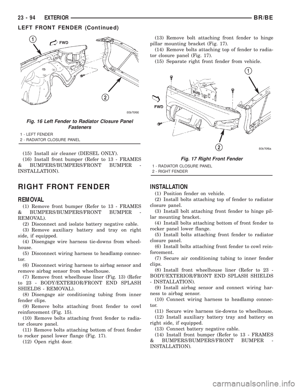
(15) Install air cleaner (DIESEL ONLY).
(16) Install front bumper (Refer to 13 - FRAMES
& BUMPERS/BUMPERS/FRONT BUMPER -
INSTALLATION).
RIGHT FRONT FENDER
REMOVAL
(1) Remove front bumper (Refer to 13 - FRAMES
& BUMPERS/BUMPERS/FRONT BUMPER -
REMOVAL).
(2) Disconnect and isolate battery negative cable.
(3) Remove auxiliary battery and tray on right
side, if equipped.
(4) Disengage wire harness tie-downs from wheel-
house.
(5) Disconnect wiring harness to headlamp connec-
tor.
(6) Disconnect wiring harness to airbag sensor and
remove airbag sensor from wheelhouse.
(7) Remove front wheelhouse liner (Fig. 13) (Refer
to 23 - BODY/EXTERIOR/FRONT END SPLASH
SHIELDS - REMOVAL).
(8) Disengage air conditioning tubing from inner
fender clips.
(9) Remove bolts attaching front fender to cowl
reinforcement (Fig. 15).
(10) Remove bolts attaching front fender to radia-
tor closure panel.
(11) Remove bolts attaching bottom of front fender
to rocker panel lower flange (Fig. 17).
(12) Open right door.(13) Remove bolt attaching front fender to hinge
pillar mounting bracket (Fig. 17).
(14) Remove bolts attaching top of fender to radia-
tor closure panel (Fig. 17).
(15) Separate right front fender from vehicle.
INSTALLATION
(1) Position fender on vehicle.
(2) Install bolts attaching top of fender to radiator
closure panel.
(3) Install bolt attaching front fender to hinge pil-
lar mounting bracket.
(4) Install bolts attaching bottom of front fender to
rocker panel lower flange.
(5) Install bolts attaching front fender to radiator
closure panel.
(6) Install bolts attaching front fender to cowl rein-
forcement.
(7) Secure air conditioning tubing to inner fender
clips.
(8) Install front wheelhouse liner (Refer to 23 -
BODY/EXTERIOR/FRONT END SPLASH SHIELDS
- INSTALLATION).
(9) Install airbag sensor and connect wiring har-
ness to airbag sensor.
(10) Connect wiring harness to headlamp connec-
tor.
(11) Secure wire harness tie-downs to wheelhouse.
(12) Install auxiliary battery tray and battery on
right side, if equipped.
(13) Connect battery negative cable.
(14) Install front bumper (Refer to 13 - FRAMES
& BUMPERS/BUMPERS/FRONT BUMPER -
INSTALLATION).
Fig. 16 Left Fender to Radiator Closure Panel
Fasteners
1 - LEFT FENDER
2 - RADIATOR CLOSURE PANEL
Fig. 17 Right Front Fender
1 - RADIATOR CLOSURE PANEL
2 - RIGHT FENDER
23 - 94 EXTERIORBR/BE
LEFT FRONT FENDER (Continued)
Page 2798 of 2889
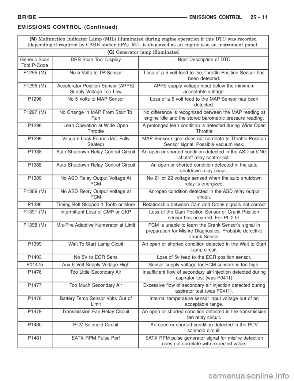
(M)Malfunction Indicator Lamp (MIL) illuminated during engine operation if this DTC was recorded
(depending if required by CARB and/or EPA). MIL is displayed as an engine icon on instrument panel.
(G)Generator lamp illuminated
Generic Scan
Tool P-CodeDRB Scan Tool Display Brief Description of DTC
P1295 (M) No 5 Volts to TP Sensor Loss of a 5 volt feed to the Throttle Position Sensor has
been detected.
P1295 (M) Accelerator Position Sensor (APPS)
Supply Voltage Too LowAPPS supply voltage input below the minimum
acceptable voltage.
P1296 No 5 Volts to MAP Sensor Loss of a 5 volt feed to the MAP Sensor has been
detected.
P1297 (M) No Change in MAP From Start To
RunNo difference is recognized between the MAP reading at
engine idle and the stored barometric pressure reading.
P1298 Lean Operation at Wide Open
ThrottleA prolonged lean condition is detected during Wide Open
Throttle
P1299 Vacuum Leak Found (IAC Fully
Seated)MAP Sensor signal does not correlate to Throttle Position
Sensor signal. Possible vacuum leak.
P1388 Auto Shutdown Relay Control Circuit An open or shorted condition detected in the ASD or CNG
shutoff relay control ckt.
P1388 Auto Shutdown Relay Control Circuit An open or shorted condition detected in the auto
shutdown relay circuit.
P1389 No ASD Relay Output Voltage At
PCMNo Z1 or Z2 voltage sensed when the auto shutdown
relay is energized.
P1389 (M) No ASD Relay Output Voltage at
PCMAn open condition detected In the ASD relay output
circuit.
P1390 Timing Belt Skipped 1 Tooth or More Relationship between Cam and Crank signals not correct
P1391 (M) Intermittent Loss of CMP or CKP Loss of the Cam Position Sensor or Crank Position
sensor has occurred. For PL 2.0L
P1398 (M) Mis-Fire Adaptive Numerator at Limit PCM is unable to learn the Crank Sensor's signal in
preparation for Misfire Diagnostics. Probable defective
Crank Sensor
P1399 Wait To Start Lamp Cicuit An open or shorted condition detected in the Wait to Start
Lamp circuit.
P1403 No 5V to EGR Sens Loss of 5v feed to the EGR position sensor.
P01475 Aux 5 Volt Supply Voltage High Sensor supply voltage for ECM sensors is too high.
P1476 Too Little Secondary Air Insufficient flow of secondary air injection detected during
aspirator test (was P0411)
P1477 Too Much Secondary Air Excessive flow of secondary air injection detected during
aspirator test (was P0411).
P1478 Battery Temp Sensor Volts Out of
LimitInternal temperature sensor input voltage out of an
acceptable range.
P1479 Transmission Fan Relay Circuit An open or shorted condition detected in the transmission
fan relay circuit.
P1480 PCV Solenoid Circuit An open or shorted condition detected in the PCV
solenoid circuit.
P1481 EATX RPM Pulse Perf EATX RPM pulse generator signal for misfire detection
does not correlate with expected value.
BR/BEEMISSIONS CONTROL 25 - 11
EMISSIONS CONTROL (Continued)