multi-function switch DODGE RAM 2001 Service Owner's Manual
[x] Cancel search | Manufacturer: DODGE, Model Year: 2001, Model line: RAM, Model: DODGE RAM 2001Pages: 2889, PDF Size: 68.07 MB
Page 726 of 2889
activates the washer pump/motor, which dispenses
washer fluid onto the windshield glass through the
washer nozzles.
When the ignition switch is in the Accessory or On
positions, battery current from a fuse in the Junction
Block (JB) is provided through a fused ignition
switch output (run-acc) circuit to the wiper motor
park switch, the wiper relay, and the multi-function
switch. The internal circuitry of the multi-function
switch provides a direct hard wired battery current
output to the low speed or high speed brushes of the
wiper motor when the Lo or Hi switch setting is
selected, which causes the wipers to cycle at the
selected speed. The intermittent wipe, and wipe-af-
ter-wash features of the wiper and washer system
are provided by the electronic intermittent wipe logic
circuit within the Central Timer Module (CTM). In
order to provide the intermittent wipe feature, the
CTM monitors the wiper switch state and the wiper
motor park switch state. In order to provide the
wipe-after-wash feature, the CTM monitors both the
washer switch state and the wiper motor park switch
state. When a Delay position is selected with the
multi-function switch control knob, the CTM logic cir-
cuit responds by calculating the correct delay inter-
val. The CTM then energizes the wiper relay by
pulling the relay control coil to ground. The ener-
gized wiper relay directs battery current through the
normally open contact of the relay back through the
internal circuitry of the multi-function switch to the
low speed brush of the wiper motor. The CTM moni-
tors the wiper motor operation through the wiper
park switch sense circuit, which allows the CTM to
determine the proper timing to begin the next wiper
blade sweep. The normal delay intervals are driver
adjustable from about one-half second to about eigh-
teen seconds.
The high-line and premium CTM also provides a
speed sensitive intermittent wipe feature. By moni-
toring vehicle speed messages received from the Pow-
ertrain Control Module (PCM) over the Chrysler
Collision Detection (CCD) data bus network, the
high-line or premium CTM is able to adjust the delay
intervals to compensate for vehicle speed. Above
about sixteen kilometers-per-hour (ten miles-per-
hour) the delay is driver adjustable from about one-
half second to about eighteen seconds. Below about
sixteen kilometers-per-hour (ten miles-per-hour) the
delay times are doubled by the CTM, from about one
second to about thirty-six seconds.
When the Off position of the multi-function switch
wiper control knob is selected, one of two events is
possible. The event that will occur depends upon the
position of the wiper blades on the windshield at the
moment that the Off position is selected. If the wiper
blades are in the down position on the windshieldwhen the Off position is selected, the park switch
that is integral to the wiper motor is closed to ground
and the wiper motor ceases to operate. If the wiper
blades are not in the down position on the windshield
at the moment the Off position is selected, the park
switch is closed to battery current through a fused
ignition switch output (run-acc) circuit. The park
switch sense circuit directs this battery current to
the low speed brush of the wiper motor through the
normally closed contact of the wiper relay and the
internal Off position circuitry of the multi-function
switch. This causes the wiper motor to continue run-
ning until the wiper blades are in the down position
on the windshield and the park switch is again
closed to ground.
When the Wash position of the multi-function
switch is selected, the Wash position circuitry within
the switch directs battery current to the washer
pump/motor. The CTM monitors the washer switch
state through a washer switch sense input. When the
washer switch is closed with the wiper system turned
Off, the CTM operates the wiper motor through the
wiper relay in the same manner as it does to provide
the Delay mode operation. After the state of the
washer switch changes to open, the CTM monitors
the wiper motor through the wiper park switch sense
circuit, which allows the CTM to monitor the number
of wiper blade sweeps.
Proper testing of the CTM, the PCM, or the CCD
data bus vehicle speed messages requires a DRBIIIt
scan tool. Refer to the appropriate diagnostic infor-
mation. Refer to the owner's manual in the vehicle
glove box for more information on the features and
operation of the wiper and washer system.
DIAGNOSIS AND TESTING - WIPER &
WASHER SYSTEM
WIPER SYSTEM
The diagnosis found here addresses an electrically
inoperative wiper system. If the wiper motor oper-
ates, but the wipers do not move on the windshield,
replace the faulty wiper module. If the wipers oper-
ate, but chatter, lift, or do not clear the glass, clean
and inspect the wiper system components as
required. (Refer to 8 - ELECTRICAL/WIPERS/
WASHERS - INSPECTION) and (Refer to 8 - ELEC-
TRICAL/WIPERS/WASHERS - CLEANING). Refer to
the appropriate wiring information. The wiring infor-
mation includes wiring diagrams, proper wire and
connector repair procedures, details of wire harness
routing and retention, connector pin-out information
and location views for the various wire harness con-
nectors, splices and grounds.
The following tests will help to diagnose the hard
wired components and circuits of the wiper system.
BR/BEWIPERS/WASHERS 8R - 3
WIPERS/WASHERS (Continued)
Page 727 of 2889
However, these tests may not prove conclusive in the
diagnosis of this system on models equipped with a
high-line or premium Central Timer Module (CTM).
In order to obtain conclusive testing of the wiper sys-
tem on models with a high-line or premium CTM, the
Chrysler Collision Detection (CCD) data bus network
and all of the electronic modules that provide inputs
to or receive outputs from the wiper system compo-
nents must be checked. The most reliable, efficient,
and accurate means to diagnose the wiper system on
models with a high-line or premium CTM requires
the use of a DRBIIItscan tool. Refer to the appro-
priate diagnostic information. The DRBIIItscan tool
can provide confirmation that the CCD data bus is
functional, that all of the electronic modules are
sending and receiving the proper messages on the
CCD data bus, and that the wiper relay is being sent
the proper hard wired outputs by the CTM for it to
perform its wiper system functions.
WARNING: ON VEHICLES EQUIPPED WITH AIR-
BAGS, DISABLE THE AIRBAG SYSTEM BEFORE
ATTEMPTING ANY STEERING WHEEL, STEERING
COLUMN, OR INSTRUMENT PANEL COMPONENT
DIAGNOSIS OR SERVICE. DISCONNECT AND ISO-
LATE THE BATTERY NEGATIVE (GROUND) CABLE,
THEN WAIT TWO MINUTES FOR THE AIRBAG SYS-
TEM CAPACITOR TO DISCHARGE BEFORE PER-
FORMING FURTHER DIAGNOSIS OR SERVICE. THIS
IS THE ONLY SURE WAY TO DISABLE THE AIRBAG
SYSTEM. FAILURE TO TAKE THE PROPER PRE-
CAUTIONS COULD RESULT IN ACCIDENTAL AIR-
BAG DEPLOYMENT AND POSSIBLE PERSONAL
INJURY.
(1) Check the fused ignition switch output (run-
acc) fuse (Fuse6-25ampere) in the Junction Block
(JB). If OK, go to Step 2. If not OK, repair the
shorted circuit or component as required and replace
the faulty fuse.
(2) Turn the ignition switch to the On position.
Check for battery voltage at the fused ignition switch
output (run-acc) fuse (Fuse6-25ampere) in the JB.
If OK, go to Step 3. If not OK, repair the open fused
ignition switch output (run-acc) circuit between the
JB and the ignition switch as required.
(3) Turn the ignition switch to the Off position.
Disconnect and isolate the battery negative cable.
Disconnect the instrument panel wire harness con-
nector for the multi-function switch from the switch
connector receptacle. Reconnect the battery negative
cable. Turn the ignition switch to the On position.
Check for battery voltage at the fused ignition switch
output (run-acc) circuit cavity of the instrument
panel wire harness connector for the multi-function
switch. If OK, go to Step 4. If not OK, repair theopen fused ignition switch output circuit between the
multi-function switch and the JB as required.
(4) If the problem being diagnosed involves only
the intermittent wipe feature, go to Step 5. If the
problem being diagnosed involves all wiper modes, or
only the Low and/or High speed modes, go to Step 7.
(5) Turn the ignition switch to the Off position.
Disconnect and isolate the battery negative cable.
Disconnect the instrument panel wire harness con-
nector (Connector C1) for the Central Timer Module
(CTM) from the CTM connector receptacle. Check for
continuity between the wiper switch mode sense cir-
cuit cavities of the instrument panel wire harness
connector for the multi-function switch and the
instrument panel wire harness connector (Connector
C1) for the CTM. There should be continuity. If OK,
go to Step 6. If not OK, repair the open wiper switch
mode sense circuit between the multi-function switch
and the CTM as required.
(6) Check for continuity between the wiper switch
mode signal circuit cavities of the instrument panel
wire harness connector for the multi-function switch
and the instrument panel wire harness connector
(Connector C1) for the CTM. There should be conti-
nuity. If OK, proceed to the diagnosis for the wiper
relay. (Refer to 8 - ELECTRICAL/WIPERS/WASH-
ERS/WIPER RELAY - DIAGNOSIS AND TESTING).
If not OK, repair the open wiper switch mode signal
circuit between the multi-function switch and the
CTM as required.
(7) Check for continuity between the two wiper
switch low speed output circuit cavities of the instru-
ment panel wire harness connector for the multi-
function switch. There should be continuity. If OK, go
to Step 8. If not OK, repair the open wiper switch
low speed output circuit between the two cavities of
the instrument panel wire harness connector for the
multi-function switch as required.
(8) Test the multi-function switch continuity.
(Refer to 8 - ELECTRICAL/LAMPS/LIGHTING -
EXTERIOR/MULTI-FUNCTION SWITCH - DIAG-
NOSIS AND TESTING). If the multi-function switch
tests OK, reconnect the instrument panel wire har-
ness connector for the multi-function switch to the
switch connector receptacle and go to Step 9. If not
OK, replace the faulty multi-function switch and test
the wiper system operation again. If still not OK, go
to Step 9.
(9) Turn the ignition switch to the Off position.
Disconnect and isolate the battery negative cable.
Measure the resistance between the headlamp and
dash wire harness ground wire for the wiper motor
and a good ground. The meter should read zero
ohms. If OK, go to Step 10. If not OK, repair the
open ground circuit to ground (G100) as required.
8R - 4 WIPERS/WASHERSBR/BE
WIPERS/WASHERS (Continued)
Page 728 of 2889
(10) Disconnect the headlamp and dash wire har-
ness connector for the wiper module from the wiper
motor pigtail wire connector. Reconnect the battery
negative cable. Turn the ignition switch to the On
position. Place the multi-function switch in the posi-
tions indicated in the tests below, and check for bat-
tery voltage at the appropriate cavity of the
headlamp and dash wire harness connector for the
wiper motor.
(a) Check for battery voltage at the fused igni-
tion switch output (run-acc) circuit cavity of the
headlamp and dash wire harness connector for the
wiper module with the multi-function switch in
any position. If OK, go to Step b. If not OK, repair
the open fused ignition switch output (run-acc) cir-
cuit between the wiper module and the JB as
required.
(b) Check for battery voltage at the wiper switch
low speed output circuit cavity of the headlamp
and dash wire harness connector for the wiper
module with the multi-function switch in the Lo
position. If OK, go to Step c. If not OK, repair the
open wiper switch low speed output circuit between
the wiper module and the multi-function switch as
required.
(c) Check for battery voltage at the wiper switch
high speed output circuit cavity of the headlamp
and dash wire harness connector for the wiper
module with the multi-function switch in the Hi
position. If OK, go to Step d. If not OK, repair the
open wiper switch high speed output circuit
between the wiper module and the multi-function
switch as required.
(d) Check for battery voltage at the wiper park
switch sense circuit cavity of the headlamp and
dash wire harness connector for the wiper module
with the multi-function switch in the Lo or Hi posi-
tion, then move the switch to the Off position. The
meter should switch between battery voltage and
zero volts while the wipers are cycling. The meter
should read battery voltage when the switch is
first moved to the Off position until the wipers
park, and then read a steady zero volts. If not OK,
replace the faulty wiper module.
WASHER SYSTEM
The diagnosis found here addresses an electrically
inoperative washer system. If the washer pump/mo-
tor operates, but no washer fluid is emitted from the
washer nozzles, be certain to check the fluid level in
the reservoir. Also inspect the washer system compo-
nents as required. (Refer to 8 - ELECTRICAL/WIP-
ERS/WASHERS - INSPECTION). Refer to the
appropriate wiring information. The wiring informa-
tion includes wiring diagrams, proper wire and con-
nector repair procedures, details of wire harnessrouting and retention, connector pin-out information
and location views for the various wire harness con-
nectors, splices and grounds.
WARNING: ON VEHICLES EQUIPPED WITH AIR-
BAGS, DISABLE THE AIRBAG SYSTEM BEFORE
ATTEMPTING ANY STEERING WHEEL, STEERING
COLUMN, OR INSTRUMENT PANEL COMPONENT
DIAGNOSIS OR SERVICE. DISCONNECT AND ISO-
LATE THE BATTERY NEGATIVE (GROUND) CABLE,
THEN WAIT TWO MINUTES FOR THE AIRBAG SYS-
TEM CAPACITOR TO DISCHARGE BEFORE PER-
FORMING FURTHER DIAGNOSIS OR SERVICE. THIS
IS THE ONLY SURE WAY TO DISABLE THE AIRBAG
SYSTEM. FAILURE TO TAKE THE PROPER PRE-
CAUTIONS COULD RESULT IN ACCIDENTAL AIR-
BAG DEPLOYMENT AND POSSIBLE PERSONAL
INJURY.
(1) Turn the ignition switch to the On position.
Turn the multi-function switch wiper control knob to
the Lo or Hi speed position. Check whether the wip-
ers operate. If OK, go to Step 2. If not OK, repair the
wiper system as required before proceeding with the
following tests. Refer to WIPER SYSTEM .
(2) Turn the multi-function switch wiper control
knob to the Off position. Depress the washer button.
The washer pump should operate and the wipers
should operate for as long as the washer button is
depressed. The wipers should continue to operate for
about three sweep cycles after the button is released
before they park. If the wipers are OK, but the wash-
ers are not, go to Step 3. If the washers are OK, but
the wipers are not, go to Step 5.
(3) Turn the ignition switch to the Off position.
Disconnect and isolate the battery negative cable.
Disconnect the headlamp and dash wire harness con-
nector for the washer pump/motor from the motor
connector receptacle. Measure the resistance between
the ground circuit cavity of the headlamp and dash
wire harness connector for the washer pump/motor
and a good ground. The meter should read zero
ohms. If OK, go to Step 4. If not OK, repair the open
ground circuit to ground (G100) as required.
(4) Reconnect the battery negative cable. Turn the
ignition switch to the On position. With the washer
button depressed, check for battery voltage at the
washer switch output circuit cavity of the headlamp
and dash wire harness connector for the washer
pump/motor. If OK, replace the faulty washer pump/
motor. If not OK, repair the open washer switch out-
put circuit between the washer pump/motor and the
multi-function switch as required.
(5) Turn the ignition switch to the Off position.
Disconnect and isolate the battery negative cable.
Disconnect the instrument panel wire harness con-
nector (Connector C1) for the Central Timer Module
BR/BEWIPERS/WASHERS 8R - 5
WIPERS/WASHERS (Continued)
Page 729 of 2889
(CTM) from the CTM connector receptacle. Reconnect
the battery negative cable. Turn the ignition switch
to the On position. With the washer button
depressed, check for battery voltage at the washer
switch sense circuit cavity of the instrument panel
wire harness connector (Connector C1) for the CTM.
If OK, proceed to the diagnosis for the wiper relay.
(Refer to 8 - ELECTRICAL/WIPERS/WASHERS/
WIPER RELAY - DIAGNOSIS AND TESTING). If
not OK, repair the open washer switch sense circuit
between the CTM and the multi-function switch as
required.
CLEANING - WIPER & WASHER SYSTEM
WIPER SYSTEM
The squeegees of wiper blades exposed to the ele-
ments for a long time tend to lose their wiping effec-
tiveness. Periodic cleaning of the squeegees is
suggested to remove any deposits of salt or road film.
The wiper blades, arms, and windshield glass should
only be cleaned using a sponge or soft cloth and
windshield washer fluid, a mild detergent, or a non-
abrasive cleaner. If the wiper blades continue to
leave streaks, smears, hazing, or beading on the
glass after thorough cleaning of the squeegees and
the glass, the entire wiper blade assembly must be
replaced.
CAUTION: Protect the rubber squeegees of the
wiper blades from any petroleum-based cleaners,
solvents, or contaminants. These products can rap-
idly deteriorate the rubber squeegees.
WASHER SYSTEM
If the washer system is contaminated with foreign
material, drain the washer reservoir by removing the
front washer pump/motor from the reservoir. Clean
foreign material from the inside of the washer reser-
voir using clean washer fluid, a mild detergent, or a
non-abrasive cleaner. Flush foreign material from the
washer system plumbing by first disconnecting the
washer hoses from the washer nozzles, then running
the washer pump/motor to run clean washer fluid or
water through the system. Plugged or restricted
washer nozzles should be carefully back-flushed
using compressed air. If the washer nozzle obstruc-
tion cannot be cleared, replace the washer nozzle.
CAUTION: Never introduce petroleum-based clean-
ers, solvents, or contaminants into the washer sys-
tem. These products can rapidly deteriorate the
rubber seals and hoses of the washer system, as
well as the rubber squeegees of the wiper blades.CAUTION: Never use compressed air to flush the
washer system plumbing. Compressed air pres-
sures are too great for the washer system plumbing
components and will result in further system dam-
age. Never use sharp instruments to clear a
plugged washer nozzle or damage to the nozzle ori-
fice and improper nozzle spray patterns will result.
INSPECTION - WIPER & WASHER SYSTEM
WIPER SYSTEM
The wiper blades and wiper arms should be
inspected periodically, not just when wiper perfor-
mance problems are experienced. This inspection
should include the following points:
(1) Inspect the wiper arms for any indications of
damage, or contamination. If the wiper arms are con-
taminated with any foreign material, clean them as
required. (Refer to 8 - ELECTRICAL/WIPERS/
WASHERS - CLEANING). If a wiper arm is damaged
or corrosion is evident, replace the wiper arm with a
new unit. Do not attempt to repair a wiper arm that
is damaged or corroded.
(2) Carefully lift the wiper blade off of the glass.
Note the action of the wiper arm hinge. The wiper
arm should pivot freely at the hinge, but with no
side-to-side looseness evident. If there is any binding
evident in the wiper arm hinge, or there is evident
side-to-side play in the wiper arm hinge, replace the
wiper arm.
CAUTION: Do not allow the wiper arm to spring
back against the glass without the wiper blade in
place or the glass may be damaged.
(3) Once proper hinge action of the wiper arm is
confirmed, check the hinge for proper spring tension.
Remove the wiper blade from the wiper arm. Either
place a small postal scale between the blade end of
the wiper arm and the glass, or carefully lift the
blade end of the arm away from the glass using a
small fish scale. Compare the scale readings between
the right and left wiper arms. Replace a wiper arm if
it has comparatively lower spring tension, as evi-
denced by a lower scale reading.
(4) Inspect the wiper blades and squeegees for any
indications of damage, contamination, or rubber dete-
rioration (Fig. 1). If the wiper blades or squeegees
are contaminated with any foreign material, clean
them and the glass as required. (Refer to 8 - ELEC-
TRICAL/WIPERS/WASHERS - CLEANING). After
cleaning the wiper blade and the glass, if the wiper
blade still fails to clear the glass without smearing,
streaking, chattering, hazing, or beading, replace the
wiper blade. Also, if a wiper blade is damaged or the
squeegee rubber is damaged or deteriorated, replace
8R - 6 WIPERS/WASHERSBR/BE
WIPERS/WASHERS (Continued)
Page 732 of 2889
be routed away from hot, sharp, or moving parts;
and, sharp bends that might pinch the hose must be
avoided.
WASHER NOZZLE
DESCRIPTION
The two washer nozzles have integral snap fea-
tures that secure them in dedicated holes in the cowl
plenum cover/grille panel located near the base of the
windshield. The domed upper surface of the washer
nozzle is visible on the top of the plenum cover/grille
panel, and the nozzle orifice is oriented towards the
windshield glass. The washer plumbing fittings for
the washer nozzles are concealed beneath the cowl
plenum cover/grille panel. These fluidic washer noz-
zles are constructed of molded plastic. The cowl ple-
num cover/grille panel must be removed from the
vehicle to access the nozzles for service. The washer
nozzles cannot be adjusted or repaired and, if faulty
or damaged, they must be replaced.
OPERATION
The two washer nozzles are designed to dispense
washer fluid into the wiper pattern area on the out-
side of the windshield glass. Pressurized washer fluid
is fed to each nozzle from the washer reservoir by the
washer pump/motor through rubber hoses, which are
attached to a barbed nipple on each washer nozzle
below the cowl plenum cover/grille panel. The washer
nozzles incorporate a fluidic design, which causes the
nozzle to emit the pressurized washer fluid as an
oscillating stream to more effectively cover a larger
area of the glass area to be cleaned.
REMOVAL
(1) Remove the cowl plenum cover/grille panel
from the cowl top. (Refer to 23 - BODY/EXTERIOR/
COWL GRILLE - REMOVAL).
(2) From the underside of the cowl plenum cover/
grille panel, disconnect the washer hose from the
nozzle fitting.
(3) From the underside of the cowl plenum cover/
grille panel, compress the snap features of the
washer nozzle and push the nozzle out through the
top of the panel.
INSTALLATION
(1) From the top of the cowl plenum cover/grille
panel, insert the barbed nipple of the washer nozzle
through the nozzle mounting hole.
(2) With the orifice of the washer nozzle oriented
toward the windshield, use hand pressure to push
the nozzle into the mounting hole until the snap fea-tures of the nozzle are fully engaged with the under-
side of the cowl plenum cover/grille panel.
(3) From the underside of the cowl plenum cover/
grille panel, reconnect the washer hose to the washer
nozzle fitting.
(4) Reinstall the cowl plenum cover/grille panel
onto the cowl top. (Refer to 23 - BODY/EXTERIOR/
COWL GRILLE - INSTALLATION).
WASHER PUMP/MOTOR
DESCRIPTION
The washer pump/motor unit is located on the rear
of the washer reservoir, near the bottom in the left
front corner of the engine compartment. A small per-
manently lubricated and sealed electric motor is cou-
pled to the rotor-type washer pump. A seal flange
with a large barbed inlet nipple on the pump housing
passes through a rubber grommet seal installed in
the dedicated mounting hole near the bottom of the
washer reservoir. A smaller barbed outlet nipple on
the pump housing connects the unit to the washer
hose. The washer pump/motor unit is retained on the
reservoir by the interference fit between the barbed
pump inlet nipple and the grommet seal, which is a
light press fit. An integral electrical connector recep-
tacle is located on the motor housing. The washer
pump/motor unit cannot be repaired. If faulty or
damaged, the entire washer pump/motor unit must
be replaced.
OPERATION
The washer pump/motor unit is connected to the
vehicle electrical system through a single take out
and two-cavity connector of the headlamp and dash
wire harness. The washer pump/motor is grounded at
all times through a take out of the headlamp and
dash wire harness with a single eyelet terminal con-
nector that is secured by a nut to a ground stud
located on the forward extension of the left front
fender wheel housing in the engine compartment.
The washer pump/motor receives battery current on
a fused ignition switch output (run-acc) circuit
through the closed contacts of the momentary washer
switch within the multi-function switch only when
the washer button on the end of the switch control
stalk is depressed towards the steering column.
Washer fluid is gravity-fed from the washer reservoir
to the inlet side of the washer pump. When the pump
motor is energized, the rotor-type pump pressurizes
the washer fluid and forces it through the pump out-
let nipple, the washer plumbing, and the washer noz-
zles onto the windshield glass.
BR/BEWIPERS/WASHERS 8R - 9
WASHER HOSES/TUBES (Continued)
Page 735 of 2889
OPERATION
The wiper arms are designed to mechanically
transmit the motion from the wiper pivots to the
wiper blades. The wiper arm must be properly
indexed to the wiper pivot in order to maintain the
proper wiper blade travel on the glass. The socket
formation with internal serrations in the wiper arm
pivot end interlocks with the serrations on the outer
circumference of the wiper pivot driver, allowing pos-
itive engagement and finite adjustment of this con-
nection. The latch plate on the underside of the
wiper arm pivot end locks the wiper arm to the wiper
pivot when in its installed position and, when in its
unlocked position, also serves as a blocker to hold the
spring-loaded wiper arm off of the glass to facilitate
removal and installation. The spring-loaded wiper
arm hinge controls the down-force applied through
the tip of the wiper arm to the wiper blade on the
glass. The hook formation on the tip of the wiper arm
provides a cradle for securing and latching the wiper
blade pivot block to the wiper arm.
REMOVAL
(1) Unlatch and open the hood.
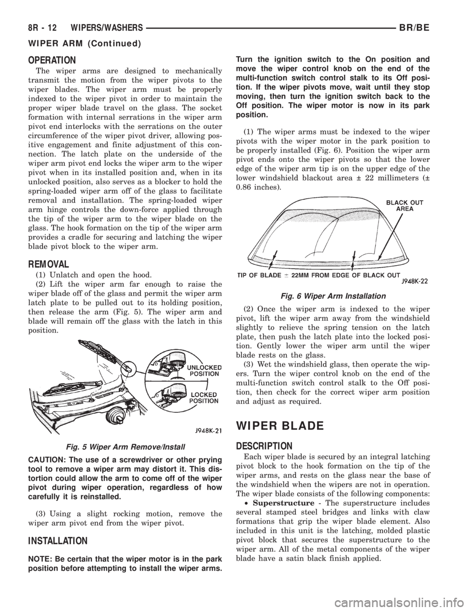
(2) Lift the wiper arm far enough to raise the
wiper blade off of the glass and permit the wiper arm
latch plate to be pulled out to its holding position,
then release the arm (Fig. 5). The wiper arm and
blade will remain off the glass with the latch in this
position.
CAUTION: The use of a screwdriver or other prying
tool to remove a wiper arm may distort it. This dis-
tortion could allow the arm to come off of the wiper
pivot during wiper operation, regardless of how
carefully it is reinstalled.
(3) Using a slight rocking motion, remove the
wiper arm pivot end from the wiper pivot.
INSTALLATION
NOTE: Be certain that the wiper motor is in the park
position before attempting to install the wiper arms.Turn the ignition switch to the On position and
move the wiper control knob on the end of the
multi-function switch control stalk to its Off posi-
tion. If the wiper pivots move, wait until they stop
moving, then turn the ignition switch back to the
Off position. The wiper motor is now in its park
position.
(1) The wiper arms must be indexed to the wiper
pivots with the wiper motor in the park position to
be properly installed (Fig. 6). Position the wiper arm
pivot ends onto the wiper pivots so that the lower
edge of the wiper arm tip is on the upper edge of the
lower windshield blackout area 22 millimeters (
0.86 inches).
(2) Once the wiper arm is indexed to the wiper
pivot, lift the wiper arm away from the windshield
slightly to relieve the spring tension on the latch
plate, then push the latch plate into the locked posi-
tion. Gently lower the wiper arm until the wiper
blade rests on the glass.
(3) Wet the windshield glass, then operate the wip-
ers. Turn the wiper control knob on the end of the
multi-function switch control stalk to the Off posi-
tion, then check for the correct wiper arm position
and adjust as required.
WIPER BLADE
DESCRIPTION
Each wiper blade is secured by an integral latching
pivot block to the hook formation on the tip of the
wiper arms, and rests on the glass near the base of
the windshield when the wipers are not in operation.
The wiper blade consists of the following components:
²Superstructure- The superstructure includes
several stamped steel bridges and links with claw
formations that grip the wiper blade element. Also
included in this unit is the latching, molded plastic
pivot block that secures the superstructure to the
wiper arm. All of the metal components of the wiper
blade have a satin black finish applied.
Fig. 5 Wiper Arm Remove/Install
Fig. 6 Wiper Arm Installation
8R - 12 WIPERS/WASHERSBR/BE
WIPER ARM (Continued)
Page 736 of 2889
²Element- The wiper element or squeegee is the
resilient rubber member of the wiper blade that con-
tacts the glass.
²Flexor- The flexor is a rigid metal component
running along the length of each side of the wiper
element where it is gripped by the claws of the
superstructure.
All Ram truck models have two 50 centimeter
(19.69 inch) wiper blades with non-replaceable rub-
ber elements (squeegees). These wiper blades also
include an anti-lift feature. The wiper blades cannot
be adjusted or repaired. If faulty, worn, or damaged
the entire wiper blade unit must be replaced.
OPERATION
The wiper blade is moved back and forth across the
glass by the wiper arms when the wipers are being
operated. The wiper blade superstructure is the flex-
ible frame that grips the wiper blade element and
evenly distributes the force of the spring-loaded
wiper arm along the length of the element. The com-
bination of the wiper arm force and the flexibility of
the superstructure makes the element conform to
and maintain proper contact with the glass, even as
the blade is moved over the varied curvature found
across the glass surface. The wiper element flexor
provides the claws of the blade superstructure with a
rigid, yet flexible component on the element which
can be gripped. The rubber element is designed to be
stiff enough to maintain an even cleaning edge as it
is drawn across the glass, but resilient enough to
conform to the glass surface and flip from one clean-
ing edge to the other each time the wiper blade
changes directions.
REMOVAL
NOTE: The driver side and passenger side wiper
blades are not interchangeable. The driver side
wiper blade has an extra bridge and eight pairs of
claws securing the wiper element. The passenger
side wiper blade has six pairs of claws securing the
wiper element. The notched retainer end of both
wiper elements should always be oriented towards
the end of the wiper blade that is nearest to the
wiper pivot.
(1) Turn the wiper control knob on the end of the
multi-function switch control stalk to the On posi-
tion. Cycle the wiper blades to a convenient working
location on the windshield by turning the ignition
switch to the On and Off positions.
(2) Lift the wiper arm to raise the wiper blade and
element off of the glass.
(3) To remove the wiper blade from the wiper arm,
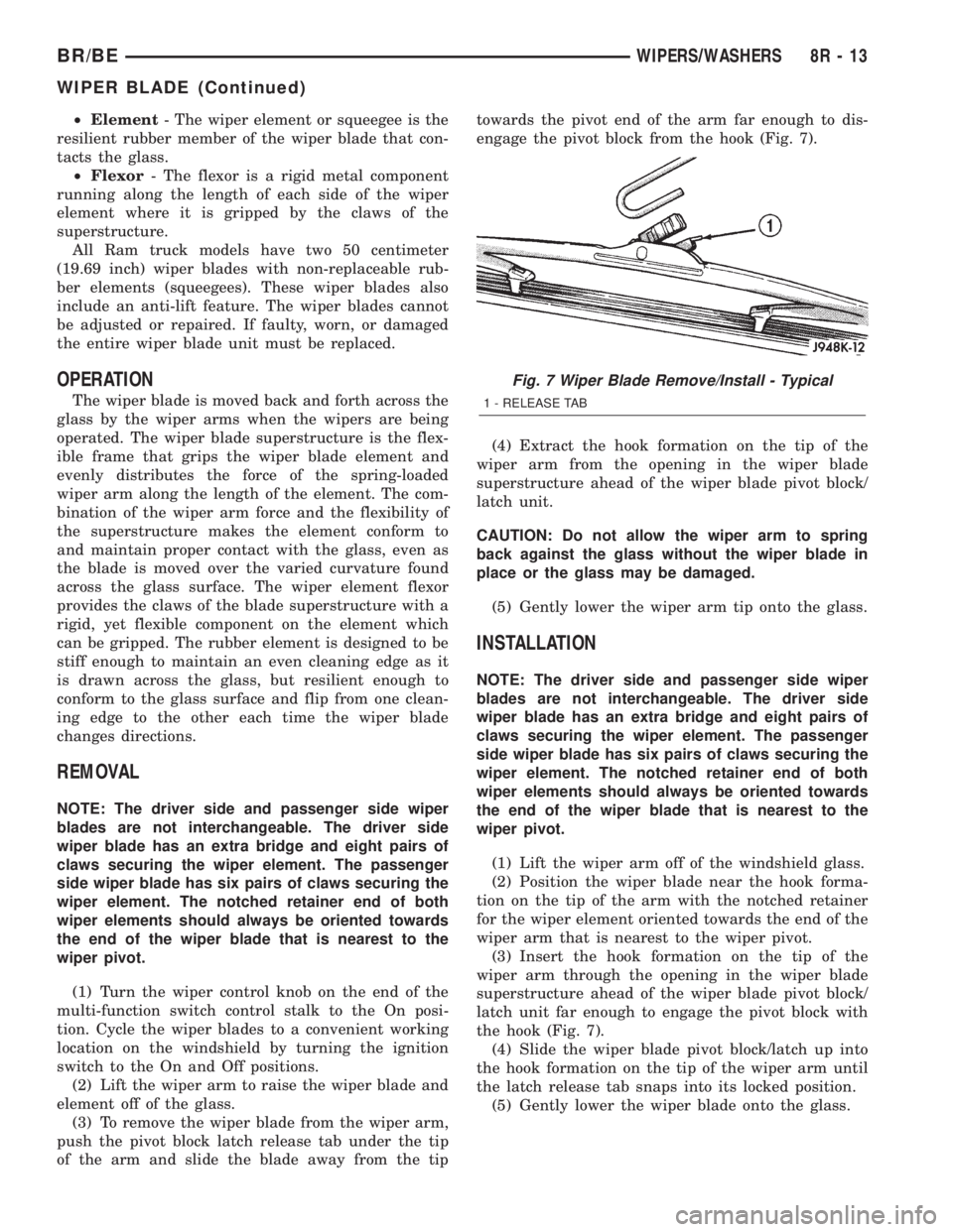
push the pivot block latch release tab under the tip
of the arm and slide the blade away from the tiptowards the pivot end of the arm far enough to dis-
engage the pivot block from the hook (Fig. 7).
(4) Extract the hook formation on the tip of the
wiper arm from the opening in the wiper blade
superstructure ahead of the wiper blade pivot block/
latch unit.
CAUTION: Do not allow the wiper arm to spring
back against the glass without the wiper blade in
place or the glass may be damaged.
(5) Gently lower the wiper arm tip onto the glass.
INSTALLATION
NOTE: The driver side and passenger side wiper
blades are not interchangeable. The driver side
wiper blade has an extra bridge and eight pairs of
claws securing the wiper element. The passenger
side wiper blade has six pairs of claws securing the
wiper element. The notched retainer end of both
wiper elements should always be oriented towards
the end of the wiper blade that is nearest to the
wiper pivot.
(1) Lift the wiper arm off of the windshield glass.
(2) Position the wiper blade near the hook forma-
tion on the tip of the arm with the notched retainer
for the wiper element oriented towards the end of the
wiper arm that is nearest to the wiper pivot.
(3) Insert the hook formation on the tip of the
wiper arm through the opening in the wiper blade
superstructure ahead of the wiper blade pivot block/
latch unit far enough to engage the pivot block with
the hook (Fig. 7).
(4) Slide the wiper blade pivot block/latch up into
the hook formation on the tip of the wiper arm until
the latch release tab snaps into its locked position.
(5) Gently lower the wiper blade onto the glass.
Fig. 7 Wiper Blade Remove/Install - Typical
1 - RELEASE TAB
BR/BEWIPERS/WASHERS 8R - 13
WIPER BLADE (Continued)
Page 737 of 2889
WIPER MODULE
DESCRIPTION
The wiper module is secured with screws to the
cowl plenum panel and concealed within the cowl
plenum area beneath the cowl plenum cover/grille
panel. The ends of the wiper pivot shafts that pro-
trude through dedicated openings in the cowl plenum
cover/grille panel to drive the wiper arms and blades
are the only visible components of the wiper module.
The wiper module consists of the following major
components:
²Bracket- The wiper module bracket consists of
a long tubular steel main member that has a
stamped pivot bracket formation near each end
where the two wiper pivots are secured. A stamped
steel mounting plate for the wiper motor is secured
with welds near the center of the main member.
²Crank Arm- The wiper motor crank arm is a
stamped steel unit that has a slotted hole on the
driven end that is secured to the wiper motor output
shaft with a nut, and has a ball stud secured to the
drive end.
²Linkage- The two wiper linkage members are
each constructed of stamped steel. A driver side drive
link with a plastic socket-type bushing in the left
end, and a plastic sleeve-type bushing in the right
end. Socket bushing is snap-fit over the pivot ball
stud on the left pivot, while the sleeve bushing is fit
over the longer wiper motor crank arm pivot stud.
The passenger side drive link has a plastic socket-
type bushing on each end. One end of this drive link
is snap-fit over the pivot ball stud on the right pivot,
while the other end is snap-fit over the exposed end
of the longer ball stud on the wiper motor crank arm.
²Motor- The wiper motor is secured with three
screws to the motor mounting plate near the center
of the wiper module bracket. The wiper motor output
shaft passes through a hole in the module bracket,
where a nut secures the wiper motor crank arm to
the motor output shaft. The two-speed permanent
magnet wiper motor features an integral transmis-
sion, an internal park switch, and an internal Posi-
tive Temperature Coefficient (PTC) circuit breaker.
²Pivots- The two wiper pivots are secured to the
ends of the wiper module bracket. The crank arms
that extend from the bottom of the pivot shafts each
have a ball stud on their end. The upper end of each
pivot shaft where the wiper arms will be fastened
each has an externally serrated drum secured to it.
The wiper module cannot be adjusted or repaired.
If any component of the module is faulty or damaged,
the entire wiper module unit must be replaced.
OPERATION
The wiper module operation is controlled by the
vehicle operator through battery current inputs
received by the wiper motor from the multi-function
switch on the steering column. The wiper motor
speed is controlled by current flow to either the low
speed or the high speed set of brushes. The park
switch is a single pole, single throw, momentary
switch within the wiper motor that is mechanically
actuated by the wiper motor transmission compo-
nents. The park switch alternately closes the wiper
park switch sense circuit to ground or to battery cur-
rent, depending upon the position of the wipers on
the glass. This feature allows the motor to complete
its current wipe cycle after the wiper system has
been turned Off, and to park the wiper blades in the
lowest portion of the wipe pattern. The automatic
resetting circuit breaker protects the motor from
overloads. The wiper motor crank arm, the two wiper
linkage members, and the two wiper pivots mechan-
ically convert the rotary output of the wiper motor to
the back and forth wiping motion of the wiper arms
and blades on the glass.
REMOVAL
(1) Disconnect and isolate the battery negative
cable.
(2) Remove the wiper arms from the wiper pivots.
(Refer to 8 - ELECTRICAL/WIPERS/WASHERS/
WIPER ARMS - REMOVAL).
(3) Remove the cowl plenum cover/grille panel
from the cowl plenum. (Refer to 23 - BODY/EXTERI-
OR/COWL GRILLE - REMOVAL).
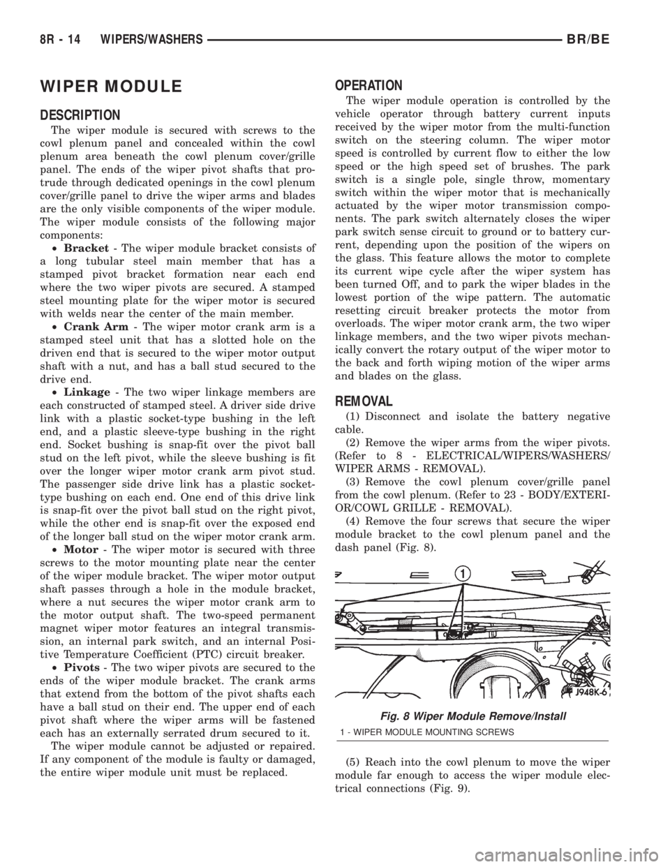
(4) Remove the four screws that secure the wiper
module bracket to the cowl plenum panel and the
dash panel (Fig. 8).
(5) Reach into the cowl plenum to move the wiper
module far enough to access the wiper module elec-
trical connections (Fig. 9).
Fig. 8 Wiper Module Remove/Install
1 - WIPER MODULE MOUNTING SCREWS
8R - 14 WIPERS/WASHERSBR/BE
Page 739 of 2889
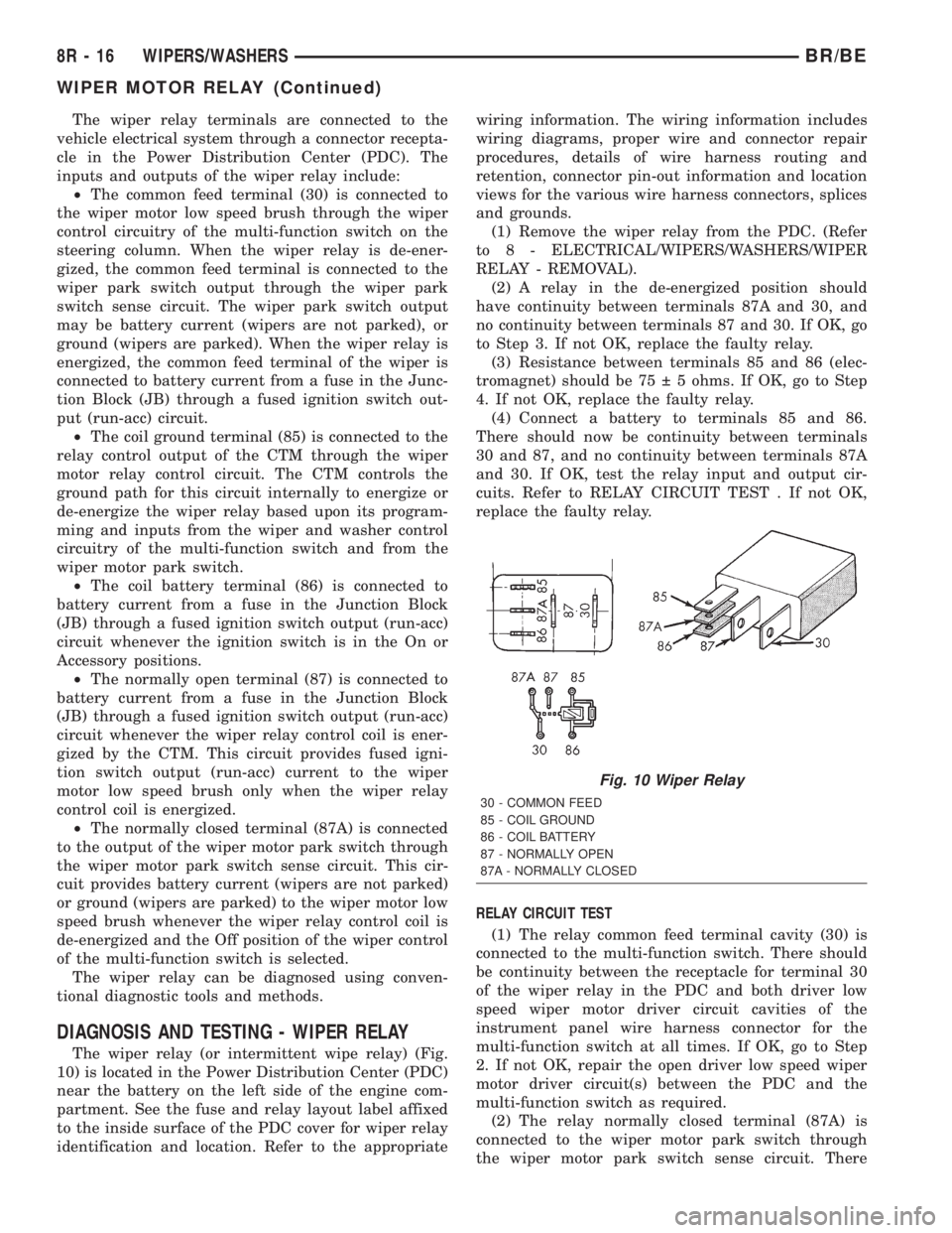
The wiper relay terminals are connected to the
vehicle electrical system through a connector recepta-
cle in the Power Distribution Center (PDC). The
inputs and outputs of the wiper relay include:
²The common feed terminal (30) is connected to
the wiper motor low speed brush through the wiper
control circuitry of the multi-function switch on the
steering column. When the wiper relay is de-ener-
gized, the common feed terminal is connected to the
wiper park switch output through the wiper park
switch sense circuit. The wiper park switch output
may be battery current (wipers are not parked), or
ground (wipers are parked). When the wiper relay is
energized, the common feed terminal of the wiper is
connected to battery current from a fuse in the Junc-
tion Block (JB) through a fused ignition switch out-
put (run-acc) circuit.
²The coil ground terminal (85) is connected to the
relay control output of the CTM through the wiper
motor relay control circuit. The CTM controls the
ground path for this circuit internally to energize or
de-energize the wiper relay based upon its program-
ming and inputs from the wiper and washer control
circuitry of the multi-function switch and from the
wiper motor park switch.
²The coil battery terminal (86) is connected to
battery current from a fuse in the Junction Block
(JB) through a fused ignition switch output (run-acc)
circuit whenever the ignition switch is in the On or
Accessory positions.
²The normally open terminal (87) is connected to
battery current from a fuse in the Junction Block
(JB) through a fused ignition switch output (run-acc)
circuit whenever the wiper relay control coil is ener-
gized by the CTM. This circuit provides fused igni-
tion switch output (run-acc) current to the wiper
motor low speed brush only when the wiper relay
control coil is energized.
²The normally closed terminal (87A) is connected
to the output of the wiper motor park switch through
the wiper motor park switch sense circuit. This cir-
cuit provides battery current (wipers are not parked)
or ground (wipers are parked) to the wiper motor low
speed brush whenever the wiper relay control coil is
de-energized and the Off position of the wiper control
of the multi-function switch is selected.
The wiper relay can be diagnosed using conven-
tional diagnostic tools and methods.
DIAGNOSIS AND TESTING - WIPER RELAY
The wiper relay (or intermittent wipe relay) (Fig.
10) is located in the Power Distribution Center (PDC)
near the battery on the left side of the engine com-
partment. See the fuse and relay layout label affixed
to the inside surface of the PDC cover for wiper relay
identification and location. Refer to the appropriatewiring information. The wiring information includes
wiring diagrams, proper wire and connector repair
procedures, details of wire harness routing and
retention, connector pin-out information and location
views for the various wire harness connectors, splices
and grounds.
(1) Remove the wiper relay from the PDC. (Refer
to 8 - ELECTRICAL/WIPERS/WASHERS/WIPER
RELAY - REMOVAL).
(2) A relay in the de-energized position should
have continuity between terminals 87A and 30, and
no continuity between terminals 87 and 30. If OK, go
to Step 3. If not OK, replace the faulty relay.
(3) Resistance between terminals 85 and 86 (elec-
tromagnet) should be 75 5 ohms. If OK, go to Step
4. If not OK, replace the faulty relay.
(4) Connect a battery to terminals 85 and 86.
There should now be continuity between terminals
30 and 87, and no continuity between terminals 87A
and 30. If OK, test the relay input and output cir-
cuits. Refer to RELAY CIRCUIT TEST . If not OK,
replace the faulty relay.
RELAY CIRCUIT TEST
(1) The relay common feed terminal cavity (30) is
connected to the multi-function switch. There should
be continuity between the receptacle for terminal 30
of the wiper relay in the PDC and both driver low
speed wiper motor driver circuit cavities of the
instrument panel wire harness connector for the
multi-function switch at all times. If OK, go to Step
2. If not OK, repair the open driver low speed wiper
motor driver circuit(s) between the PDC and the
multi-function switch as required.
(2) The relay normally closed terminal (87A) is
connected to the wiper motor park switch through
the wiper motor park switch sense circuit. There
Fig. 10 Wiper Relay
30 - COMMON FEED
85 - COIL GROUND
86 - COIL BATTERY
87 - NORMALLY OPEN
87A - NORMALLY CLOSED
8R - 16 WIPERS/WASHERSBR/BE
WIPER MOTOR RELAY (Continued)
Page 1016 of 2889
Component Page
Left Speed Control Switch............ 8W-80-58
Left Tail/Stop/Turn Signal Lamp........ 8W-80-58
Left Tweeter (Premium).............. 8W-80-58
Left Visor/Vanity Lamp............... 8W-80-58
Low Note Horn..................... 8W-80-58
Manifold ABSolute Pressure Sensor
(3.9L/5.2L/5.9L)................... 8W-80-58
Manifold ABSolute Pressure Sensor
(8.0L).......................... 8W-80-59
Manifold Air Pressure Sensor (Diesel).... 8W-80-59
Multi-Function Switch............... 8W-80-59
Output Speed Sensor................ 8W-80-59
Overdrive Switch................... 8W-80-60
Overhead Console (Base).............. 8W-80-60
Overhead Console (Highline)........... 8W-80-60
Oxygen Sensor 1/1 Left Bank Up
(5.9L HD/8.0L)................... 8W-80-60
Oxygen Sensor 1/1 Left Bank Up
(California)...................... 8W-80-60
Oxygen Sensor 1/1 Upstream
(A/T Except 8.0L)................. 8W-80-61
Oxygen Sensor 1/1 Upstream
(M/T Except 8.0L)................. 8W-80-61
Oxygen Sensor 1/2 Downstream
(3.9L/5.2L)....................... 8W-80-61
Oxygen Sensor 1/2 Left Bank Down
(California)...................... 8W-80-61
Oxygen Sensor 1/2 Pre-Catalyst (8.0L) . . . 8W-80-61
Oxygen Sensor 1/3 Post Catalyst (8.0L) . . 8W-80-62
Oxygen Sensor 2/1 Right Bank Up (5.9L HD)
(5.2L/5.9L/8.0L California).......... 8W-80-62
Oxygen Sensor 2/2 Right Bank Down
(California)...................... 8W-80-62
Park/Neutral Position Switch
(A/T Except 8.0L)................. 8W-80-62
Park/Neutral Position Switch (A/T 8.0L) . . 8W-80-62
Passenger Airbag................... 8W-80-63
Passenger Airbag On/Off Switch C1..... 8W-80-63
Passenger Airbag On/Off Switch C2..... 8W-80-63
Passenger Cylinder Lock Switch........ 8W-80-63
Passenger Door Ajar Switch........... 8W-80-63
Passenger Door Lock Motor........... 8W-80-63
Passenger Door Window/Lock Switch.... 8W-80-64
Passenger Heated Seat Cushion........ 8W-80-64
Passenger Heated Seat Switch......... 8W-80-64
Passenger Lumbar Motor............. 8W-80-64
Passenger Power Seat Front Vertical Motor
(Club Cab)....................... 8W-80-64
Passenger Power Seat Horizontal Motor
(Club Cab)....................... 8W-80-65
Passenger Power Seat Rear Vertical Motor
(Club Cab)....................... 8W-80-65Component Page
Passenger Power Seat Switch
(Club Cab)....................... 8W-80-65
Passenger Power Window Motor........ 8W-80-65
Power Mirror Switch................. 8W-80-65
Power Outlet....................... 8W-80-66
Powertrain Control Module C1 (Diesel) . . . 8W-80-66
Powertrain Control Module C1 (Gas).... 8W-80-67
Powertrain Control Module C2 (Diesel) . . . 8W-80-67
Powertrain Control Module C2 (Gas).... 8W-80-68
Powertrain Control Module C3 (Diesel) . . . 8W-80-69
Powertrain Control Module C3 (Gas).... 8W-80-70
Radio C1.......................... 8W-80-70
Radio C2.......................... 8W-80-71
Radio C3.......................... 8W-80-71
Radio Choke Relay.................. 8W-80-71
Rear Wheel Speed Sensor (ABS)........ 8W-80-71
Right Back-Up Lamp................ 8W-80-71
Right Fog Lamp.................... 8W-80-72
Right Front Door Speaker (Premium).... 8W-80-72
Right Front Door Speaker (Standard).... 8W-80-72
Right Front Fender Lamp
(Dual Rear Wheels)................ 8W-80-72
Right Front Wheel Speed Sensor (ABS) . . 8W-80-72
Right Headlamp.................... 8W-80-73
Right License Lamp................. 8W-80-73
Right Outboard Clearance Lamp....... 8W-80-73
Right Outboard Headlamp............ 8W-80-73
Right Outboard Identification Lamp..... 8W-80-73
Right Park/Turn Signal Lamp.......... 8W-80-73
Right Power Mirror.................. 8W-80-74
Right Rear Fender Lamp
(Dual Rear Wheels)................ 8W-80-74
Right Rear Speaker (2 Door Premium) . . . 8W-80-74
Right Rear Speaker (4 Door Premium) . . . 8W-80-74
Right Rear Speaker (Standard 2 Door) . . . 8W-80-74
Right Rear Speaker (Standard 4 Door) . . . 8W-80-74
Right Remote Radio Switch........... 8W-80-75
Right Speed Control Switch........... 8W-80-75
Right Tail/Stop/Turn Signal Lamp...... 8W-80-75
Right Tweeter (Premium)............. 8W-80-75
Right Visor/Vanity Lamp.............. 8W-80-75
Seat Belt Switch (Club Cab)........... 8W-80-75
Seat Belt Switch (Standard Cab)....... 8W-80-76
Seat Heat Interface Module........... 8W-80-76
Speed Control Servo................. 8W-80-76
Tailgate Lamp (Dual Rear Wheels)...... 8W-80-76
Throttle Position Sensor (Gas)......... 8W-80-76
Trailer Tow Connector................ 8W-80-77
Transmission Solenoid Assembly........ 8W-80-77
Underhood Lamp................... 8W-80-77
Washer Fluid Level Switch............ 8W-80-77
Water In Fuel Sensor (Diesel).......... 8W-80-78
Wiper Motor....................... 8W-80-78
BR/BE8W-80 CONNECTOR PIN-OUTS 8W - 80 - 3