multi-function switch DODGE RAM 2001 Service User Guide
[x] Cancel search | Manufacturer: DODGE, Model Year: 2001, Model line: RAM, Model: DODGE RAM 2001Pages: 2889, PDF Size: 68.07 MB
Page 622 of 2889
spring mechanism rotates with the steering wheel
and the cam lobes contact the cancel actuator when
it is extended from the multi-function switch. When
the steering wheel is rotated during a turning
maneuver, one of the two turn signal cancel cam
lobes will contact the turn signal cancel actuator. The
cancel actuator latches against the cancel cam rota-
tion in the direction opposite that which is signaled.
In other words, if the left turn signal detent is
selected, the lobes of the cancel cam will ratchet past
the cancel actuator when the steering wheel is
rotated to the left, but will unlatch the cancel actua-
tor as the steering wheel rotates to the right and
returns to center, which will cancel the turn signal
event and release the control stalk from the detent so
it returns to the neutral Off position.
²Washer Mode- Pushing the button on the end
of the multi-function switch control knob towards the
steering column provides a battery current output
through the momentary single pole, single throw
washer switch circuitry to operate the washer pump/
motor and provides a signal to the CTM. If the wip-
ers are not operating when the washer switch is
actuated, the CTM will operate the wiper motor for
as long as the washer switch is depressed plus about
three additional wipe cycles. If the wipers are oper-
ating in the intermittent mode when the washer
switch is actuated, the CTM will operate the wiper
motor at a fixed low speed for as long as the washer
switch is depressed plus about three additional wipe
cycles before the wipers return to the selected inter-
mittent wipe interval.DIAGNOSIS AND TESTING - MULTI-FUNCTION
SWITCH
Refer to the appropriate wiring information. The
wiring information includes wiring diagrams, proper
wire and connector repair procedures, details of wire
harness routing and retention, connector pin-out
information and location views for the various wire
harness connectors, splices and grounds.
WARNING: ON VEHICLES EQUIPPED WITH AIR-
BAGS, DISABLE THE AIRBAG SYSTEM BEFORE
ATTEMPTING ANY STEERING WHEEL, STEERING
COLUMN, OR INSTRUMENT PANEL COMPONENT
DIAGNOSIS OR SERVICE. DISCONNECT AND ISO-
LATE THE BATTERY NEGATIVE (GROUND) CABLE,
THEN WAIT TWO MINUTES FOR THE AIRBAG SYS-
TEM CAPACITOR TO DISCHARGE BEFORE PER-
FORMING FURTHER DIAGNOSIS OR SERVICE. THIS
IS THE ONLY SURE WAY TO DISABLE THE AIRBAG
SYSTEM. FAILURE TO TAKE THE PROPER PRE-
CAUTIONS COULD RESULT IN ACCIDENTAL AIR-
BAG DEPLOYMENT AND POSSIBLE PERSONAL
INJURY.
(1) Disconnect and isolate the battery negative
cable. Disconnect the instrument panel wire harness
connector from the multi-function switch connector
receptacle.
(2) Using an ohmmeter, perform the continuity
and resistance tests at the terminals in the multi-
function switch connector receptacle as shown in the
Multi-Function Switch Tests chart (Fig. 25).
BR/BELAMPS/LIGHTING - EXTERIOR 8L - 25
MULTI-FUNCTION SWITCH (Continued)
Page 623 of 2889
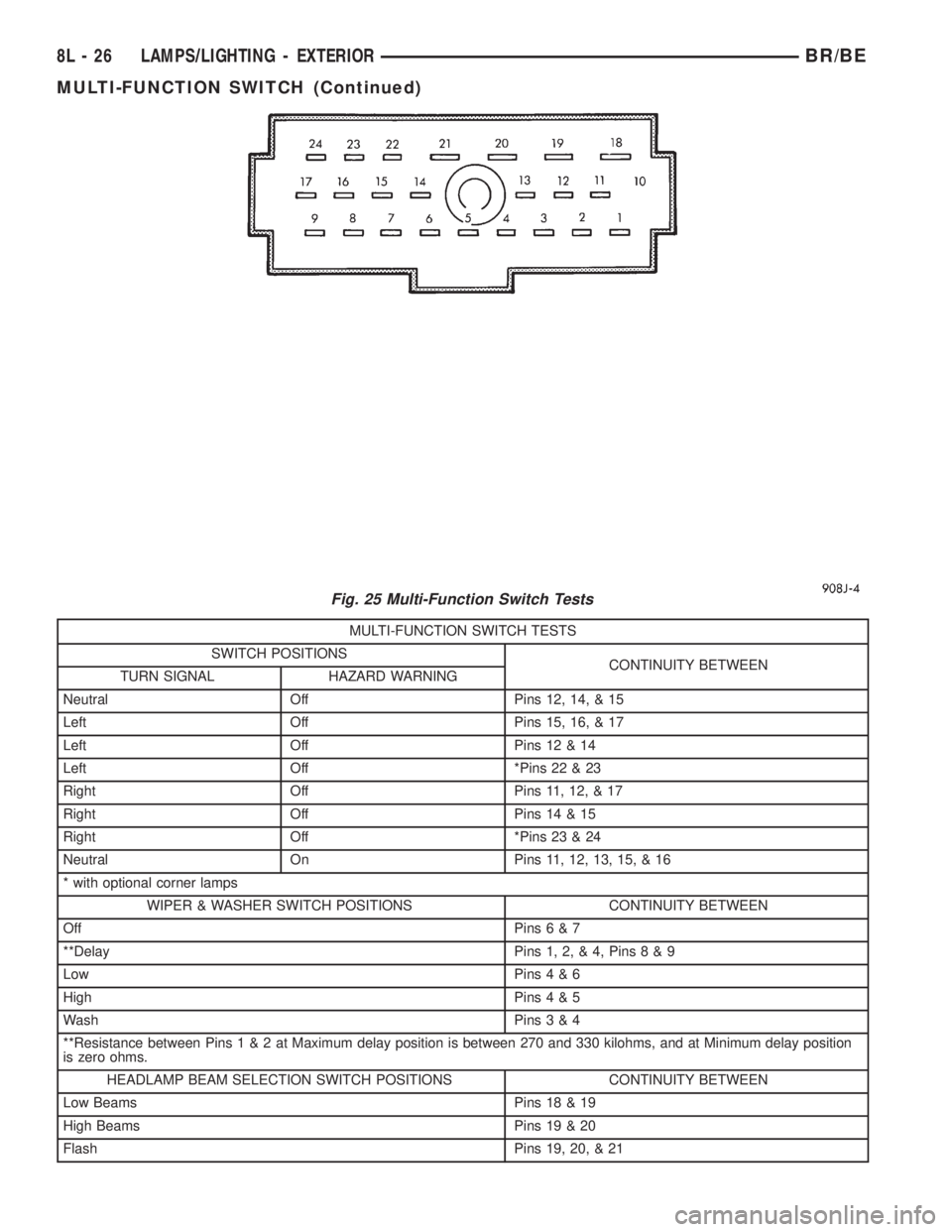
MULTI-FUNCTION SWITCH TESTS
SWITCH POSITIONS
CONTINUITY BETWEEN
TURN SIGNAL HAZARD WARNING
Neutral Off Pins 12, 14, & 15
Left Off Pins 15, 16, & 17
Left Off Pins 12 & 14
Left Off *Pins 22 & 23
Right Off Pins 11, 12, & 17
Right Off Pins 14 & 15
Right Off *Pins 23 & 24
Neutral On Pins 11, 12, 13, 15, & 16
* with optional corner lamps
WIPER & WASHER SWITCH POSITIONS CONTINUITY BETWEEN
Off Pins6&7
**Delay Pins 1, 2, & 4, Pins8&9
Low Pins4&6
High Pins4&5
Wash Pins3&4
**Resistance between Pins1&2atMaximum delay position is between 270 and 330 kilohms, and at Minimum delay position
is zero ohms.
HEADLAMP BEAM SELECTION SWITCH POSITIONS CONTINUITY BETWEEN
Low Beams Pins 18 & 19
High Beams Pins 19 & 20
Flash Pins 19, 20, & 21
Fig. 25 Multi-Function Switch Tests
8L - 26 LAMPS/LIGHTING - EXTERIORBR/BE
MULTI-FUNCTION SWITCH (Continued)
Page 624 of 2889
(3) If the multi-function switch fails any of the
continuity or resistance tests, replace the faulty
switch unit as required.
REMOVAL
WARNING: ON VEHICLES EQUIPPED WITH AIR-
BAGS, DISABLE THE AIRBAG SYSTEM BEFORE
ATTEMPTING ANY STEERING WHEEL, STEERING
COLUMN, OR INSTRUMENT PANEL COMPONENT
DIAGNOSIS OR SERVICE. DISCONNECT AND ISO-
LATE THE BATTERY NEGATIVE (GROUND) CABLE,
THEN WAIT TWO MINUTES FOR THE AIRBAG SYS-
TEM CAPACITOR TO DISCHARGE BEFORE PER-
FORMING FURTHER DIAGNOSIS OR SERVICE. THIS
IS THE ONLY SURE WAY TO DISABLE THE AIRBAG
SYSTEM. FAILURE TO TAKE THE PROPER PRE-
CAUTIONS COULD RESULT IN ACCIDENTAL AIR-
BAG DEPLOYMENT AND POSSIBLE PERSONAL
INJURY.
(1) Disconnect and isolate the battery negative
cable.
(2) If the vehicle is so equipped, unscrew the lever
from the tilt steering column adjuster mechanism
located on the left side of the column just below the
multi-function switch control stalk. Turn the lever
counterclockwise to unscrew it from the adjuster.
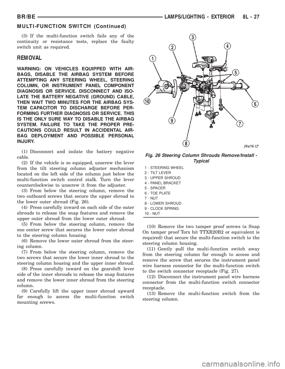
(3) From below the steering column, remove the
two outboard screws that secure the upper shroud to
the lower outer shroud (Fig. 26).
(4) Press carefully inward on each side of the outer
shrouds to release the snap features and remove the
upper outer shroud from the lower outer shroud.
(5) From below the steering column, remove the
one center screw that secures the lower outer shroud
to the steering column housing.
(6) Remove the lower outer shroud from the steer-
ing column.
(7) From below the steering column, remove the
two screws that secure the lower inner shroud to the
steering column housing and the upper inner shroud.
(8) Press carefully inward on the gearshift lever
side of the inner shrouds to release the snap features
and remove the lower inner shroud from the steering
column.
(9) Carefully lift the upper inner shroud upward
far enough to access the multi-function switch
mounting screws.(10) Remove the two tamper proof screws (a Snap
On tamper proof Torx bit TTXR20B2 or equivalent is
required) that secure the multi-function switch to the
steering column housing.
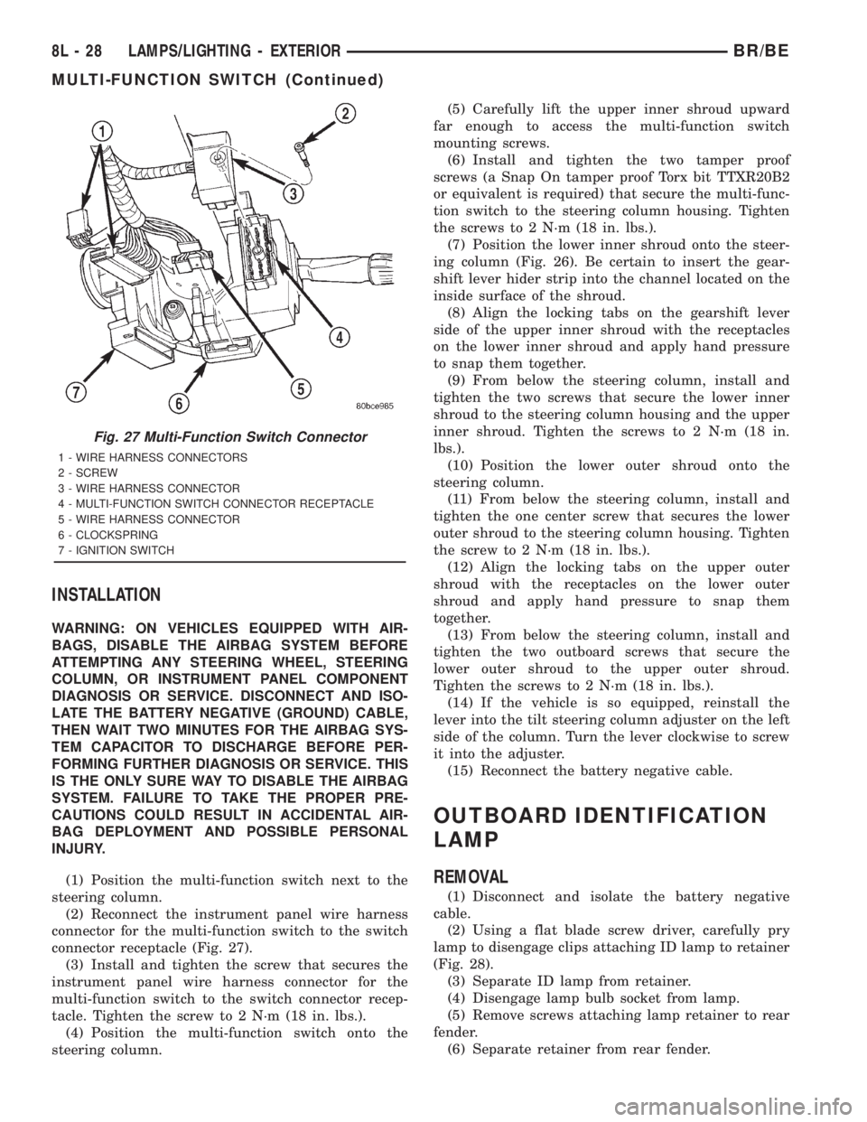
(11) Gently pull the multi-function switch away
from the steering column far enough to access and
remove the screw that secures the instrument panel
wire harness connector for the multi-function switch
to the switch connector receptacle (Fig. 27).
(12) Disconnect the instrument panel wire harness
connector from the multi-function switch connector
receptacle.
(13) Remove the multi-function switch from the
steering column.
Fig. 26 Steering Column Shrouds Remove/Install -
Typical
1 - STEERING WHEEL
2 - TILT LEVER
3 - UPPER SHROUD
4 - PANEL BRACKET
5 - SPACER
6 - TOE PLATE
7 - NUT
8 - LOWER SHROUD
9 - CLOCK SPRING
10 - NUT
BR/BELAMPS/LIGHTING - EXTERIOR 8L - 27
MULTI-FUNCTION SWITCH (Continued)
Page 625 of 2889
INSTALLATION
WARNING: ON VEHICLES EQUIPPED WITH AIR-
BAGS, DISABLE THE AIRBAG SYSTEM BEFORE
ATTEMPTING ANY STEERING WHEEL, STEERING
COLUMN, OR INSTRUMENT PANEL COMPONENT
DIAGNOSIS OR SERVICE. DISCONNECT AND ISO-
LATE THE BATTERY NEGATIVE (GROUND) CABLE,
THEN WAIT TWO MINUTES FOR THE AIRBAG SYS-
TEM CAPACITOR TO DISCHARGE BEFORE PER-
FORMING FURTHER DIAGNOSIS OR SERVICE. THIS
IS THE ONLY SURE WAY TO DISABLE THE AIRBAG
SYSTEM. FAILURE TO TAKE THE PROPER PRE-
CAUTIONS COULD RESULT IN ACCIDENTAL AIR-
BAG DEPLOYMENT AND POSSIBLE PERSONAL
INJURY.
(1) Position the multi-function switch next to the
steering column.
(2) Reconnect the instrument panel wire harness
connector for the multi-function switch to the switch
connector receptacle (Fig. 27).
(3) Install and tighten the screw that secures the
instrument panel wire harness connector for the
multi-function switch to the switch connector recep-
tacle. Tighten the screw to 2 N´m (18 in. lbs.).
(4) Position the multi-function switch onto the
steering column.(5) Carefully lift the upper inner shroud upward
far enough to access the multi-function switch
mounting screws.
(6) Install and tighten the two tamper proof
screws (a Snap On tamper proof Torx bit TTXR20B2
or equivalent is required) that secure the multi-func-
tion switch to the steering column housing. Tighten
the screws to 2 N´m (18 in. lbs.).
(7) Position the lower inner shroud onto the steer-
ing column (Fig. 26). Be certain to insert the gear-
shift lever hider strip into the channel located on the
inside surface of the shroud.
(8) Align the locking tabs on the gearshift lever
side of the upper inner shroud with the receptacles
on the lower inner shroud and apply hand pressure
to snap them together.
(9) From below the steering column, install and
tighten the two screws that secure the lower inner
shroud to the steering column housing and the upper
inner shroud. Tighten the screws to 2 N´m (18 in.
lbs.).
(10) Position the lower outer shroud onto the
steering column.
(11) From below the steering column, install and
tighten the one center screw that secures the lower
outer shroud to the steering column housing. Tighten
the screw to 2 N´m (18 in. lbs.).
(12) Align the locking tabs on the upper outer
shroud with the receptacles on the lower outer
shroud and apply hand pressure to snap them
together.
(13) From below the steering column, install and
tighten the two outboard screws that secure the
lower outer shroud to the upper outer shroud.
Tighten the screws to 2 N´m (18 in. lbs.).
(14) If the vehicle is so equipped, reinstall the
lever into the tilt steering column adjuster on the left
side of the column. Turn the lever clockwise to screw
it into the adjuster.
(15) Reconnect the battery negative cable.
OUTBOARD IDENTIFICATION
LAMP
REMOVAL
(1) Disconnect and isolate the battery negative
cable.
(2) Using a flat blade screw driver, carefully pry
lamp to disengage clips attaching ID lamp to retainer
(Fig. 28).
(3) Separate ID lamp from retainer.
(4) Disengage lamp bulb socket from lamp.
(5) Remove screws attaching lamp retainer to rear
fender.
(6) Separate retainer from rear fender.
Fig. 27 Multi-Function Switch Connector
1 - WIRE HARNESS CONNECTORS
2 - SCREW
3 - WIRE HARNESS CONNECTOR
4 - MULTI-FUNCTION SWITCH CONNECTOR RECEPTACLE
5 - WIRE HARNESS CONNECTOR
6 - CLOCKSPRING
7 - IGNITION SWITCH
8L - 28 LAMPS/LIGHTING - EXTERIORBR/BE
MULTI-FUNCTION SWITCH (Continued)
Page 628 of 2889
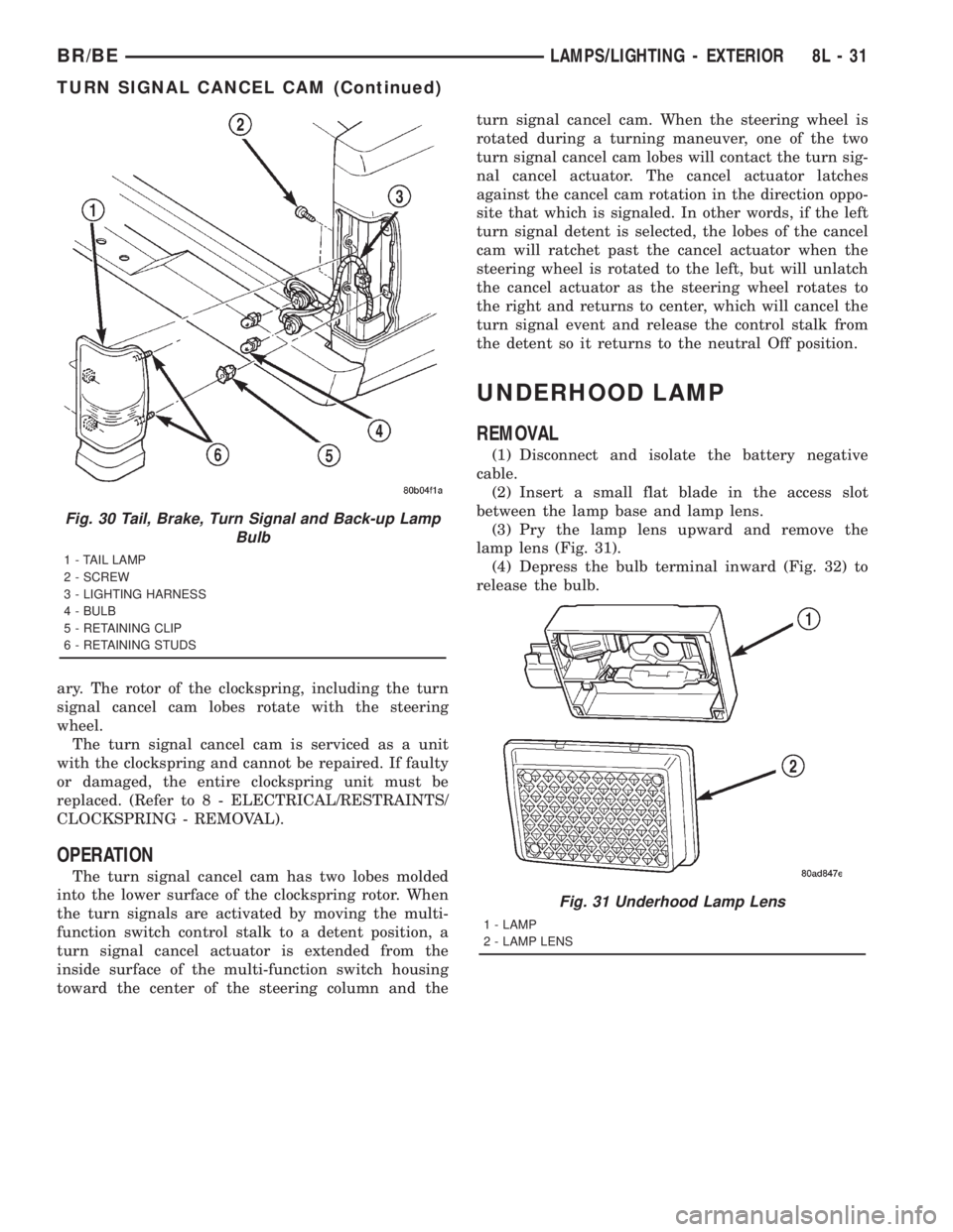
ary. The rotor of the clockspring, including the turn
signal cancel cam lobes rotate with the steering
wheel.
The turn signal cancel cam is serviced as a unit
with the clockspring and cannot be repaired. If faulty
or damaged, the entire clockspring unit must be
replaced. (Refer to 8 - ELECTRICAL/RESTRAINTS/
CLOCKSPRING - REMOVAL).
OPERATION
The turn signal cancel cam has two lobes molded
into the lower surface of the clockspring rotor. When
the turn signals are activated by moving the multi-
function switch control stalk to a detent position, a
turn signal cancel actuator is extended from the
inside surface of the multi-function switch housing
toward the center of the steering column and theturn signal cancel cam. When the steering wheel is
rotated during a turning maneuver, one of the two
turn signal cancel cam lobes will contact the turn sig-
nal cancel actuator. The cancel actuator latches
against the cancel cam rotation in the direction oppo-
site that which is signaled. In other words, if the left
turn signal detent is selected, the lobes of the cancel
cam will ratchet past the cancel actuator when the
steering wheel is rotated to the left, but will unlatch
the cancel actuator as the steering wheel rotates to
the right and returns to center, which will cancel the
turn signal event and release the control stalk from
the detent so it returns to the neutral Off position.
UNDERHOOD LAMP
REMOVAL
(1) Disconnect and isolate the battery negative
cable.
(2) Insert a small flat blade in the access slot
between the lamp base and lamp lens.
(3) Pry the lamp lens upward and remove the
lamp lens (Fig. 31).
(4) Depress the bulb terminal inward (Fig. 32) to
release the bulb.
Fig. 30 Tail, Brake, Turn Signal and Back-up Lamp
Bulb
1 - TAIL LAMP
2 - SCREW
3 - LIGHTING HARNESS
4 - BULB
5 - RETAINING CLIP
6 - RETAINING STUDS
Fig. 31 Underhood Lamp Lens
1 - LAMP
2 - LAMP LENS
BR/BELAMPS/LIGHTING - EXTERIOR 8L - 31
TURN SIGNAL CANCEL CAM (Continued)
Page 661 of 2889
REMOVAL
(1) Disconnect and isolate the battery negative
cable.
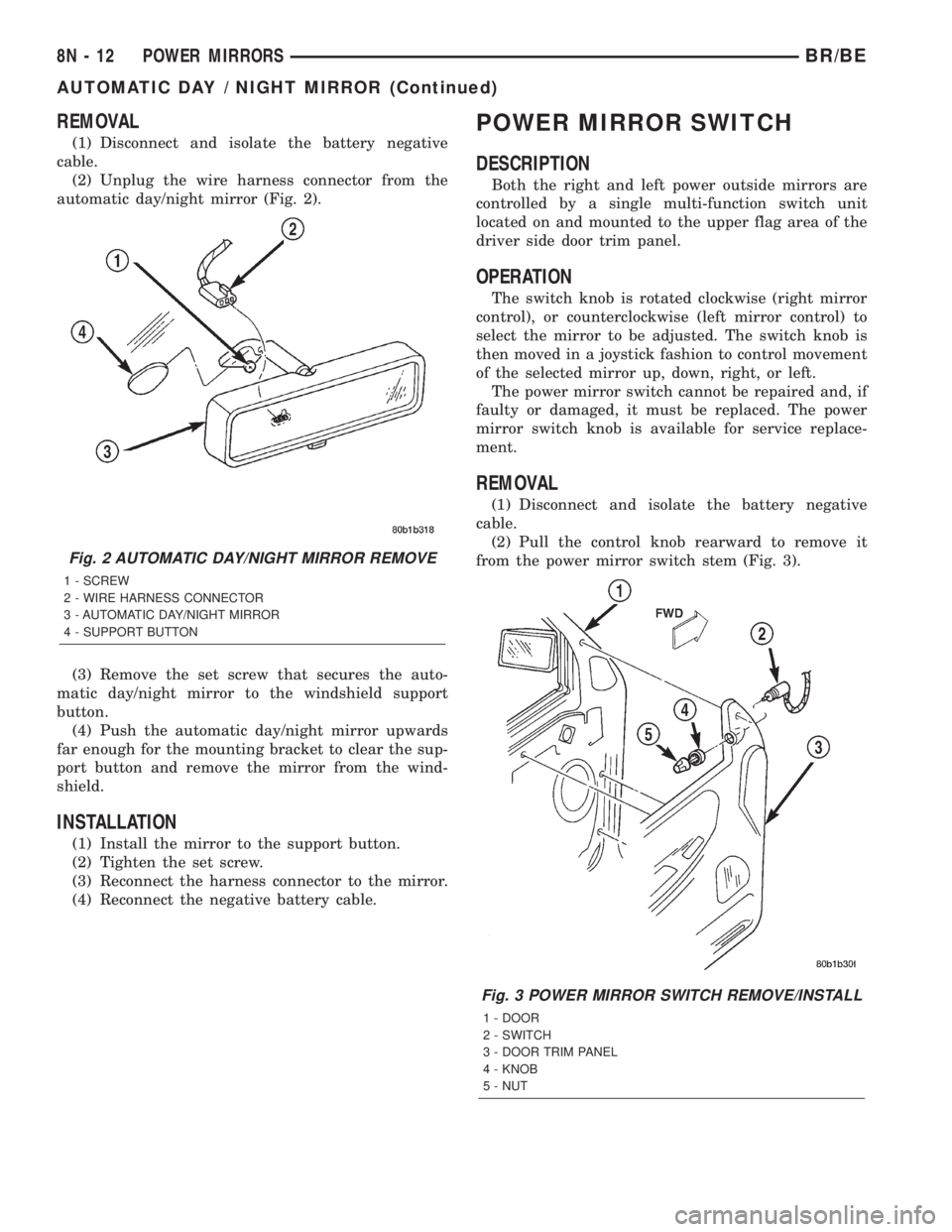
(2) Unplug the wire harness connector from the
automatic day/night mirror (Fig. 2).
(3) Remove the set screw that secures the auto-
matic day/night mirror to the windshield support
button.
(4) Push the automatic day/night mirror upwards
far enough for the mounting bracket to clear the sup-
port button and remove the mirror from the wind-
shield.
INSTALLATION
(1) Install the mirror to the support button.
(2) Tighten the set screw.
(3) Reconnect the harness connector to the mirror.
(4) Reconnect the negative battery cable.
POWER MIRROR SWITCH
DESCRIPTION
Both the right and left power outside mirrors are
controlled by a single multi-function switch unit
located on and mounted to the upper flag area of the
driver side door trim panel.
OPERATION
The switch knob is rotated clockwise (right mirror
control), or counterclockwise (left mirror control) to
select the mirror to be adjusted. The switch knob is
then moved in a joystick fashion to control movement
of the selected mirror up, down, right, or left.
The power mirror switch cannot be repaired and, if
faulty or damaged, it must be replaced. The power
mirror switch knob is available for service replace-
ment.
REMOVAL
(1) Disconnect and isolate the battery negative
cable.
(2) Pull the control knob rearward to remove it
from the power mirror switch stem (Fig. 3).
Fig. 2 AUTOMATIC DAY/NIGHT MIRROR REMOVE
1 - SCREW
2 - WIRE HARNESS CONNECTOR
3 - AUTOMATIC DAY/NIGHT MIRROR
4 - SUPPORT BUTTON
Fig. 3 POWER MIRROR SWITCH REMOVE/INSTALL
1 - DOOR
2 - SWITCH
3 - DOOR TRIM PANEL
4 - KNOB
5 - NUT
8N - 12 POWER MIRRORSBR/BE
AUTOMATIC DAY / NIGHT MIRROR (Continued)
Page 685 of 2889
(1) Position the child tether anchor (standard cab)
or child tether (club/quad cab) onto the cab back
panel (Fig. 7).
(2) Install and tighten the screw that secures the
child tether anchor (standard cab) or child tether
(club/quad cab) onto the cab back panel. Tighten the
screw to 13.5 N´m (120 in. lbs.).
(3) Reinstall the trim onto the inside of the cab
back panel. (Refer to 23 - BODY/INTERIOR/REAR
CLOSURE PANEL TRIM - INSTALLATION).
CLOCKSPRING
DESCRIPTION
The clockspring assembly is secured with two inte-
gral plastic latches onto the steering column lock
housing near the top of the steering column, behind
the steering wheel. The clockspring consists of a flat,
round molded plastic case with a stubby tail that
hangs below the steering column and contains a con-
nector receptacle and a long pigtail wire with connec-
tor that face toward the instrument panel. Within
the plastic housing is a spool-like molded plastic
rotor with a large exposed hub. The upper surface of
the rotor hub has a large center hole, two large flats,
two auto-locking tabs, and three short pigtail wires
with connectors that face toward the steering wheel.
The lower surface of the rotor hub has two integral
turn signal cancelling cam lobes. Within the plastic
case and wound around the rotor spool is a long rib-
bon-like tape that consists of several thin copper wire
leads sandwiched between two thin plastic mem-
branes. The outer end of the tape terminates at the
connector receptacle and pigtail wire that face the
instrument panel, while the inner end of the tape
terminates at the pigtail wires on the hub of the
clockspring rotor that face the steering wheel.
Service replacement clocksprings are shipped pre-
centered and with a piece of tape covering the
engaged auto-locking tabs. The auto-locking tabs
secure the centered clockspring rotor to the clock-
spring case during shipment, but these tabs are auto-
matically disengaged once the clockspring is installed
on the steering column. (Refer to 8 - ELECTRICAL/
RESTRAINTS/CLOCKSPRING - STANDARD PRO-
CEDURE - CLOCKSPRING CENTERING).
The clockspring cannot be repaired. If the clock-
spring is faulty, damaged, or if the driver airbag has
been deployed, the clockspring must be replaced.
OPERATION
The clockspring is a mechanical electrical circuit
component that is used to provide continuous electri-
cal continuity between the fixed instrument panel
wire harness and the electrical components mountedon or in the rotating steering wheel. On this model
the rotating electrical components include the driver
airbag, the horn switch, the speed control switches,
and the remote radio switches if the vehicle is so
equipped. The clockspring case is positioned and
secured to the upper steering column lock housing by
two integral plastic latches. The connector receptacle
on the tail of the fixed clockspring housing connect
the clockspring to the vehicle electrical system
through a take out with connector from the instru-
ment panel wire harness. The lower clockspring pig-
tail on the tail of the clockspring housing connect the
clockspring driver airbag circuits to a separate take
out and connector of the instrument panel wire har-
ness located near the lower instrument panel rein-
forcement, below the steering column. The
clockspring rotor is movable and is keyed to the hub
of the steering wheel by two large flats that are
molded into the rotor hub. The two lobes on the
lower surface of the clockspring rotor hub contact a
turn signal cancel actuator of the multi-function
switch to provide automatic turn signal cancellation.
The pigtail wires on the upper surface of the clock-
spring connect the clockspring to the horn switch, the
two speed control switches, and the remote radio
switches on vehicles that are so equipped.
Like the clockspring in a timepiece, the clockspring
tape has travel limits and can be damaged by being
wound too tightly during full stop-to-stop steering
wheel rotation. To prevent this from occurring, the
clockspring must be centered when it is installed on
the steering column. Centering the clockspring
indexes the clockspring spool to the movable steering
components so that the tape can operate within its
designed travel limits. However, if the clockspring is
removed from the steering column or if the steering
shaft is disconnected from the steering gear, the
clockspring spool can change position relative to the
movable steering components and must be re-cen-
tered following completion of the service or the tape
may be damaged. Service replacement clocksprings
are shipped pre-centered and with the auto-locking
tabs engaged. A piece of tape covers the auto-locking
tabs to discourage tampering. These auto-locking
tabs should not be disengaged until the clockspring
has been installed on the steering column. If this
shipping tape is removed or damaged, or if the auto-
locking tabs are disengaged before the clockspring is
installed on a steering column, the clockspring cen-
tering procedure must be performed. (Refer to 8 -
ELECTRICAL/RESTRAINTS/CLOCKSPRING -
STANDARD PROCEDURE - CLOCKSPRING CEN-
TERING).
8O - 10 RESTRAINTSBR/BE
CHILD TETHER (Continued)
Page 687 of 2889
WARNING: DISABLE THE AIRBAG SYSTEM
BEFORE ATTEMPTING ANY STEERING WHEEL,
STEERING COLUMN, OR INSTRUMENT PANEL
COMPONENT DIAGNOSIS OR SERVICE. DISCON-
NECT AND ISOLATE THE BATTERY NEGATIVE
(GROUND) CABLE, THEN WAIT TWO MINUTES FOR
THE AIRBAG SYSTEM CAPACITOR TO DISCHARGE
BEFORE PERFORMING FURTHER DIAGNOSIS OR
SERVICE. THIS IS THE ONLY SURE WAY TO DIS-
ABLE THE AIRBAG SYSTEM. FAILURE TO TAKE
THE PROPER PRECAUTIONS COULD RESULT IN
ACCIDENTAL AIRBAG DEPLOYMENT AND POSSI-
BLE PERSONAL INJURY.
NOTE: Before starting this procedure, be certain to
turn the steering wheel until the front wheels are in
the straight-ahead position.
(1) Place the front wheels in the straight-ahead
position.
(2) Remove the driver airbag from the steering
wheel. (Refer to 8 - ELECTRICAL/RESTRAINTS/
DRIVER AIRBAG - REMOVAL).
(3) If the vehicle is so equipped, disconnect the
clockspring pigtail wire connectors from the speed
control switches and the remote radio switches
located within the hub cavity of the steering wheel.
(4) Remove the nut that secures the steering wheel
armature to the steering column upper shaft, which
is located within the hub cavity of the steering wheel.
(5) Pull the steering wheel off of the steering col-
umn upper shaft spline using a steering wheel puller
(Special Tool C-3428-B).
(6) Remove the steering column opening cover
from the instrument panel. (Refer to 23 - BODY/IN-
STRUMENT PANEL/STEERING COLUMN OPEN-
ING COVER - REMOVAL).
(7) If the vehicle is so equipped, unscrew the lever
from the tilt steering column adjuster mechanism
located on the left side of the column just below the
multi-function switch control stalk. Turn the lever
counterclockwise to unscrew it from the adjuster.
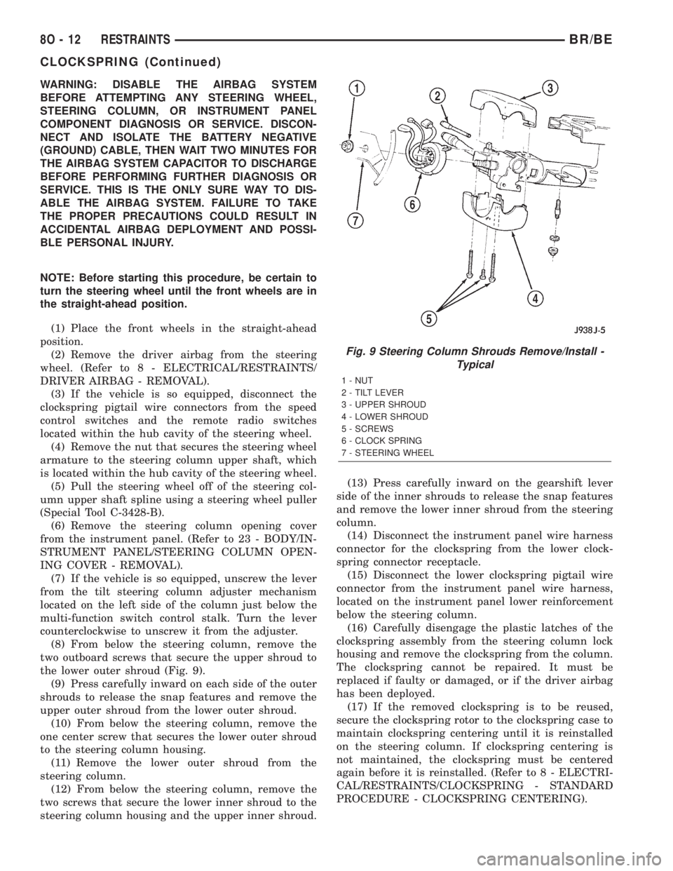
(8) From below the steering column, remove the
two outboard screws that secure the upper shroud to
the lower outer shroud (Fig. 9).
(9) Press carefully inward on each side of the outer
shrouds to release the snap features and remove the
upper outer shroud from the lower outer shroud.
(10) From below the steering column, remove the
one center screw that secures the lower outer shroud
to the steering column housing.
(11) Remove the lower outer shroud from the
steering column.
(12) From below the steering column, remove the
two screws that secure the lower inner shroud to the
steering column housing and the upper inner shroud.(13) Press carefully inward on the gearshift lever
side of the inner shrouds to release the snap features
and remove the lower inner shroud from the steering
column.
(14) Disconnect the instrument panel wire harness
connector for the clockspring from the lower clock-
spring connector receptacle.
(15) Disconnect the lower clockspring pigtail wire
connector from the instrument panel wire harness,
located on the instrument panel lower reinforcement
below the steering column.
(16) Carefully disengage the plastic latches of the
clockspring assembly from the steering column lock
housing and remove the clockspring from the column.
The clockspring cannot be repaired. It must be
replaced if faulty or damaged, or if the driver airbag
has been deployed.
(17) If the removed clockspring is to be reused,
secure the clockspring rotor to the clockspring case to
maintain clockspring centering until it is reinstalled
on the steering column. If clockspring centering is
not maintained, the clockspring must be centered
again before it is reinstalled. (Refer to 8 - ELECTRI-
CAL/RESTRAINTS/CLOCKSPRING - STANDARD
PROCEDURE - CLOCKSPRING CENTERING).
Fig. 9 Steering Column Shrouds Remove/Install -
Typical
1 - NUT
2 - TILT LEVER
3 - UPPER SHROUD
4 - LOWER SHROUD
5 - SCREWS
6 - CLOCK SPRING
7 - STEERING WHEEL
8O - 12 RESTRAINTSBR/BE
CLOCKSPRING (Continued)
Page 724 of 2889
WIPERS/WASHERS
TABLE OF CONTENTS
page page
WIPERS/WASHERS
DESCRIPTION............................1
OPERATION.............................2
DIAGNOSIS AND TESTING..................3
WIPER & WASHER SYSTEM...............3
CLEANING...............................6
INSPECTION.............................6
WASHER FLUID LEVEL SWITCH
DESCRIPTION............................7
OPERATION.............................7
REMOVAL...............................8
INSTALLATION............................8
WASHER HOSES/TUBES
DESCRIPTION............................8
OPERATION.............................8
WASHER NOZZLE
DESCRIPTION............................9
OPERATION.............................9
REMOVAL...............................9
INSTALLATION............................9
WASHER PUMP/MOTOR
DESCRIPTION............................9
OPERATION.............................9
REMOVAL..............................10
INSTALLATION...........................10
WASHER RESERVOIR
DESCRIPTION...........................10OPERATION.............................10
REMOVAL..............................10
INSTALLATION...........................11
WIPER ARM
DESCRIPTION...........................11
OPERATION.............................12
REMOVAL..............................12
INSTALLATION...........................12
WIPER BLADE
DESCRIPTION...........................12
OPERATION.............................13
REMOVAL..............................13
INSTALLATION...........................13
WIPER MODULE
DESCRIPTION...........................14
OPERATION.............................14
REMOVAL..............................14
INSTALLATION...........................15
WIPER RELAY
DESCRIPTION...........................15
OPERATION.............................15
DIAGNOSIS AND TESTING.................16
WIPER RELAY.........................16
REMOVAL..............................17
INSTALLATION...........................17
WIPERS/WASHERS
DESCRIPTION
An electrically operated intermittent wiper and
washer system is standard factory-installed safety
equipment on this model. The wiper and washer sys-
tem includes the following major components, which
are described in further detail elsewhere in this ser-
vice information:
²Central Timer Module- The Central Timer
Module (CTM) is located under the driver side end of
the instrument panel, inboard of the instrument
panel steering column opening. A base version of the
CTM is used on base models of this vehicle. The base
version of the CTM combines the functions of a
chime module and an intermittent wipe module in a
single unit. The high-line version of the CTM is used
on high-line vehicles. The high-line CTM provides all
of the functions of the base version of the CTM, but
also is used to control and integrate many additionalelectronic functions and features included on high-
line models. The premium version of the CTM is the
same as the high-line version, but is used only on
models equipped with the heated seat option. The
high-line and premium versions of the CTM contain
integrated circuitry, a central processing unit and the
programming to provide all of the proper wiper and
washer system features based upon the monitored
inputs. The high-line and premium CTM circuitry
monitors hard wired switch inputs, as well as mes-
sage inputs received from other vehicle electronic
modules on the Chrysler Collision Detection (CCD)
data bus network. (Refer to 8 - ELECTRICAL/ELEC-
TRONIC CONTROL MODULES/BODY CONTROL/
CENTRAL TIMER MODULE - DESCRIPTION).
²Multi-Function Switch- The multi-function
switch is secured to the left side of the steering col-
umn, just below the steering wheel. Only the control
stalk for the multi-function switch is visible, the
remainder of the switch is concealed beneath the
steering column shrouds. The multi-function switch
BR/BEWIPERS/WASHERS 8R - 1
Page 725 of 2889
contains all of the switches for both the wiper and
washer systems.
²Washer Fluid Level Switch- The washer fluid
level switch is located in a dedicated hole on the
lower rear side of the washer reservoir, above the
washer pump/motor unit near the left front corner of
the engine compartment.
²Washer Nozzles- The dual fluidic washer noz-
zles are secured with integral snap features to dedi-
cated openings in the cowl plenum cover/grille panel
located near the base of the windshield. The washer
plumbing fittings for the washer nozzles are con-
cealed beneath the cowl plenum cover/grille panel.
²Washer Pump/Motor- The washer pump/mo-
tor unit is located in a dedicated hole on the lower
rear side of the washer reservoir near the left front
corner of the engine compartment.
²Washer Reservoir- The washer reservoir is
secured to the left side of the radiator fan shroud in
the left front corner of the engine compartment.
²Wiper Arms- The two wiper arms are secured
to the two wiper pivots, which extend through the
cowl plenum cover/grille panel located near the base
of the windshield.
²Wiper Blades- The two wiper blades are
secured to the two wiper arms, and are parked on
the glass near the bottom of the windshield when the
wiper system is not in operation.
²Wiper Module- The wiper pivots are the only
visible components of the wiper module. The remain-
der of the module is concealed within the cowl ple-
num beneath the cowl plenum cover/grille panel. The
wiper module includes the module bracket, the single
wiper motor, the wiper linkage, and the two wiper
pivots.
²Wiper Relay- The wiper relay is located in the
Power Distribution Center (PDC) in the engine com-
partment near the battery.
Features of the wiper and washer system include
the following:
²Continuous Wipe Modes- The two-speed
wiper motor and the internal circuitry of the multi-
function switch work in concert to provide two con-
tinuous wipe cycles, low speed or high speed.
²Intermittent Wipe Mode- The internal cir-
cuitry of the multi-function switch, the CTM, and the
wiper relay work in concert to provide an intermit-
tent wipe mode with multiple delay interval selec-
tions. On models with a high-line or premium CTM,
the CTM also automatically adjusts each manually
selected delay interval to compensate for vehicle
speed.
²Washer Mode- When the washer system is
activated with the multi-function switch while the
wiper system is operating, washer fluid will be dis-
pensed onto the windshield glass through the washernozzles for as long as the washer pump/motor is
energized.
²Wipe-After-Wash Mode- The internal circuitry
of the CTM provides a wipe-after-wash feature
which, if the wipers are turned Off, will operate the
washer pump/motor and the wipers for as long as the
washer system is activated, then provide several
additional wipe cycles after the washer system is
deactivated before parking the wiper blades near the
base of the windshield.
Hard wired circuitry connects the wiper and
washer system components to the electrical system of
the vehicle. These hard wired circuits are integral to
several wire harnesses, which are routed throughout
the vehicle and retained by many different methods.
These circuits may be connected to each other, to the
vehicle electrical system and to the wiper and washer
system components through the use of a combination
of soldered splices, splice block connectors, and many
different types of wire harness terminal connectors
and insulators. Refer to the appropriate wiring infor-
mation. The wiring information includes wiring dia-
grams, proper wire and connector repair procedures,
further details on wire harness routing and reten-
tion, as well as pin-out and location views for the
various wire harness connectors, splices and grounds.
OPERATION
The wiper and washer system is intended to pro-
vide the vehicle operator with a convenient, safe, and
reliable means of maintaining visibility through the
windshield glass. The various components of this sys-
tem are designed to convert electrical energy pro-
duced by the vehicle electrical system into the
mechanical action of the wiper blades to wipe the
outside surface of the glass, as well as into the
hydraulic action of the washer system to apply
washer fluid stored in an on-board reservoir to the
area of the glass to be wiped. When combined, these
components provide the means to effectively main-
tain clear visibility for the vehicle operator by remov-
ing excess accumulations of rain, snow, bugs, mud, or
other minor debris from the outside windshield glass
surface that might be encountered while driving the
vehicle under numerous types of inclement operating
conditions. The vehicle operator initiates all wiper
and washer system functions with the multi-function
switch control stalk that extends from the left side of
the steering column, just below the steering wheel.
Rotating the knob on the end of the multi-function
switch control stalk selects the desired wiper system
operating mode. The wiper system allows the vehicle
operator to select from two continuous wiper speeds,
Hi or Lo, or one of several intermittent wipe Delay
mode intervals. Pushing the button on the end of the
control stalk downwards towards the steering column
8R - 2 WIPERS/WASHERSBR/BE
WIPERS/WASHERS (Continued)