multi-function switch DODGE RAM 2001 Service Repair Manual
[x] Cancel search | Manufacturer: DODGE, Model Year: 2001, Model line: RAM, Model: DODGE RAM 2001Pages: 2889, PDF Size: 68.07 MB
Page 581 of 2889
bol icon for ªHigh Beamº in the opaque layer of the
instrument cluster overlay. The dark outer layer of
the overlay prevents the indicator from being clearly
visible when it is not illuminated. A blue lens behind
the cutout in the opaque layer of the overlay causes
the icon to appear in blue through the translucent
outer layer of the overlay when it is illuminated from
behind by a replaceable incandescent bulb and bulb
holder unit located on the instrument cluster elec-
tronic circuit board. The high beam indicator is ser-
viced as a unit with the instrument cluster.
OPERATION
The high beam indicator gives an indication to the
vehicle operator when the headlamp high beams are
illuminated. This indicator is hard wired on the
instrument cluster electronic circuit board, and is
controlled by a headlamp beam select switch input to
the cluster. The headlamp high beam indicator bulb
receives battery current on the instrument cluster
electronic circuit board through a fused B(+) circuit
at all times; therefore, the indicator remains opera-
tional regardless of the ignition switch position. The
headlamp beam select switch is integral to the multi-
function switch on the left side of the steering col-
umn, and is connected in series between ground and
the headlamp high beam indicator. The indicator
bulb only illuminates when it is provided with a path
to ground through the high beam indicator driver cir-
cuit by the headlamp beam select switch. (Refer to 8
- ELECTRICAL/LAMPS/LIGHTING - EXTERIOR/
MULTI-FUNCTION SWITCH - OPERATION). The
high beam indicator can be diagnosed using conven-
tional diagnostic tools and methods.
DIAGNOSIS AND TESTING - HIGH BEAM
INDICATOR
The diagnosis found here addresses an inoperative
headlamp high beam indicator condition. If the prob-
lem being diagnosed is related to inoperative head-
lamp high beams, be certain to repair the headlamp
system before attempting to diagnose or repair the
high beam indicator. If no headlamp system problems
are found, the following procedure will help locate a
short or open in the high beam indicator circuit.
Refer to the appropriate wiring information. The wir-
ing information includes wiring diagrams, proper
wire and connector repair procedures, details of wire
harness routing and retention, connector pin-out
information and location views for the various wire
harness connectors, splices and grounds.
WARNING: ON VEHICLES EQUIPPED WITH AIR-
BAGS, DISABLE THE AIRBAG SYSTEM BEFORE
ATTEMPTING ANY STEERING WHEEL, STEERING
COLUMN, OR INSTRUMENT PANEL COMPONENTDIAGNOSIS OR SERVICE. DISCONNECT AND ISO-
LATE THE BATTERY NEGATIVE (GROUND) CABLE,
THEN WAIT TWO MINUTES FOR THE AIRBAG SYS-
TEM CAPACITOR TO DISCHARGE BEFORE PER-
FORMING FURTHER DIAGNOSIS OR SERVICE. THIS
IS THE ONLY SURE WAY TO DISABLE THE AIRBAG
SYSTEM. FAILURE TO TAKE THE PROPER PRE-
CAUTIONS COULD RESULT IN ACCIDENTAL AIR-
BAG DEPLOYMENT AND POSSIBLE PERSONAL
INJURY.
INDICATOR DOES NOT ILLUMINATE WITH HIGH BEAMS
SELECTED
(1) Check the fused B(+) fuse (Fuse 14 - 10
ampere) in the Junction Block (JB). If OK, go to Step
2. If not OK, repair the shorted circuit or component
as required and replace the faulty fuse.
(2) Check for battery voltage at the fused B(+) fuse
(Fuse 14 - 10 ampere) in the JB. If OK, go to Step 3.
If not OK, repair the open fused B(+) circuit between
the JB and the Power Distribution Center (PDC) as
required.
(3) Be certain that the headlamp high beams are
selected with the headlamp beam select switch by
turning the headlamp switch to the On position, pull-
ing the multi-function switch stalk toward the steer-
ing wheel, then inspecting the headlamps at the
front of the vehicle. Once the headlamp high beams
are selected, turn the headlamp switch to the Off
position.
(4) Disconnect and isolate the battery negative
cable. Remove the instrument cluster from the
instrument panel. Reconnect the battery negative
cable. Check for battery voltage at the fused B(+) cir-
cuit cavity of the instrument panel wire harness con-
nector (Connector C1) for the instrument cluster. If
OK, go to . If not OK, repair the open fused B(+) cir-
cuit between the instrument cluster and the JB as
required.
(5) Disconnect and isolate the battery negative
cable. Check for continuity between the high beam
indicator driver circuit cavity of the instrument panel
wire harness connector (Connector C2) for the instru-
ment cluster and a good ground. There should be
continuity. If OK, replace the faulty headlamp high
beam indicator bulb and bulb holder unit. If not OK,
repair the open high beam indicator driver circuit
between the instrument cluster and the headlamp
beam select (multi-function) switch as required.
INDICATOR STAYS ILLUMINATED WITH HIGH BEAMS NOT
SELECTED
(1) Be certain that the headlamp low beams are
selected with the headlamp beam select switch by
turning the headlamp switch to the On position, pull-
ing the multi-function switch stalk toward the steer-
8J - 22 INSTRUMENT CLUSTERBR/BE
HIGH BEAM INDICATOR (Continued)
Page 582 of 2889
ing wheel, then inspecting the headlamps at the
front of the vehicle. Once the headlamp low beams
are selected, turn the headlamp switch to the Off
position.
(2) Disconnect and isolate the battery negative
cable. Remove the instrument cluster from the
instrument panel. Check for continuity between the
high beam indicator driver circuit cavity of the
instrument panel wire harness connector (Connector
C2) for the instrument cluster and a good ground.
There should be no continuity. If OK, replace the
faulty instrument cluster. If not OK, repair the
shorted high beam indicator driver circuit between
the instrument cluster and the headlamp beam select
(multi-function) switch as required.
LOW FUEL INDICATOR
DESCRIPTION
A low fuel indicator is standard equipment on all
instrument clusters. The low fuel indicator is located
near the lower edge of the instrument cluster overlay,
to the right of center. The low fuel indicator consists
of a stenciled cutout of the International Control and
Display Symbol icon for ªFuelº in the opaque layer of
the instrument cluster overlay. The dark outer layer
of the overlay prevents the indicator from being
clearly visible when it is not illuminated. An amber
lens behind the cutout in the opaque layer of the
overlay causes the icon to appear in amber through
the translucent outer layer of the overlay when the
indicator is illuminated from behind by a Light Emit-
ting Diode (LED) soldered onto the instrument clus-
ter electronic circuit board. The low fuel indicator
lamp is serviced as a unit with the instrument clus-
ter.
OPERATION
The low fuel indicator gives an indication to the
vehicle operator when the level of fuel in the fuel
tank becomes low. This indicator is controlled by a
transistor on the instrument cluster circuit board
based upon cluster programming and electronic mes-
sages received by the cluster from the Powertrain
Control Module (PCM) over the Chrysler Collision
Detection (CCD) data bus. The low fuel indicator
Light Emitting Diode (LED) receives battery current
on the instrument cluster electronic circuit board
through the fused ignition switch output (st-run) cir-
cuit whenever the ignition switch is in the On or
Start positions; therefore, the LED will always be off
when the ignition switch is in any position except On
or Start. The LED only illuminates when it is pro-
vided a path to ground by the instrument clustertransistor. The instrument cluster will turn on the
low fuel indicator for the following reasons:
²Bulb Test- Each time the ignition switch is
turned to the On position the indicator is illuminated
for about two seconds as a bulb test.
²Less Than 12.5 Percent Tank Full Message-
Each time the cluster receives messages from the
PCM indicating the percent tank full is 12.5 (one-
eighth) or less for 10 consecutive seconds and the
vehicle speed is zero, or for 60 consecutive seconds
and the vehicle speed is greater than zero, the low
fuel indicator is illuminated and a single chime tone
is sounded. The low fuel indicator remains illumi-
nated until the cluster receives messages from the
PCM indicating that the percent tank full is greater
than 12.5 (one-eighth) for 10 consecutive seconds and
the vehicle speed is zero, or for 60 consecutive sec-
onds and the vehicle speed is greater than zero, or
until the ignition switch is turned to the Off position,
whichever occurs first. The chime tone feature will
only repeat during the same ignition cycle if the low
fuel indicator is cycled off and then on again by the
appropriate percent tank full messages from the
PCM.
²Less Than Empty Percent Tank Full Mes-
sage- Each time the cluster receives a message from
the PCM indicating the percent tank full is less than
empty, the low fuel indicator is illuminated immedi-
ately. This message would indicate that the fuel tank
sender input to the PCM is a short circuit.
²More Than Full Percent Tank Full Message
- Each time the cluster receives a message from the
PCM indicating the percent tank full is more than
full, the low fuel indicator is illuminated immedi-
ately. This message would indicate that the fuel tank
sender input to the PCM is an open circuit.
²Actuator Test- Each time the cluster is put
through the actuator test, the indicator will be
turned on during the bulb check portion of the test to
confirm the functionality of the LED and the cluster
control circuitry.
The PCM continually monitors the fuel tank send-
ing unit, then sends the proper messages to the
instrument cluster. For further diagnosis of the low
fuel indicator or the instrument cluster circuitry that
controls the LED, (Refer to 8 - ELECTRICAL/IN-
STRUMENT CLUSTER - DIAGNOSIS AND TEST-
ING). For proper diagnosis of the fuel tank sending
unit, the PCM, the CCD data bus, or the message
inputs to the instrument cluster that control the low
fuel indicator, a DRBIIItscan tool is required. Refer
to the appropriate diagnostic information.
BR/BEINSTRUMENT CLUSTER 8J - 23
HIGH BEAM INDICATOR (Continued)
Page 591 of 2889
(st-run) circuit whenever the ignition switch is in the
On or Start positions; therefore, the LED will always
be off when the ignition switch is in any position
except On or Start. The LED bulb only illuminates
when it is provided a path to ground by the instru-
ment cluster transistor. The instrument cluster will
turn on the transmission over-temperature indicator
for the following reasons:
²Bulb Test- Each time the ignition switch is
turned to the On position the transmission over-tem-
perature indicator is illuminated for about two sec-
onds as a bulb test.
²Trans Over-Temp Lamp-On Message- Each
time the cluster receives a trans over-temp lamp-on
message from the PCM indicating that the transmis-
sion fluid temperature is 135É C (275É F) or higher,
the indicator will be illuminated and a single chime
tone is sounded. The lamp remains illuminated until
the cluster receives a trans over-temp lamp-off mes-
sage from the PCM, or until the ignition switch is
turned to the Off position, whichever occurs first.
The chime tone feature will only repeat during the
same ignition cycle if the transmission over-tempera-
ture indicator is cycled off and then on again by the
appropriate trans over-temp messages from the PCM.
²Actuator Test- Each time the cluster is put
through the actuator test, the indicator will be
turned on during the bulb check portion of the test to
confirm the functionality of the LED and the cluster
control circuitry.
The PCM continually monitors the transmission
temperature sensor to determine the transmission
operating condition, then sends the proper messages
to the instrument cluster. If the instrument cluster
turns on the transmission over-temperature indicator
due to a high transmission oil temperature condition,
it may indicate that the transmission and/or the
transmission cooling system are being overloaded or
that they require service. For further diagnosis of the
transmission over-temperature indicator or the
instrument cluster circuitry that controls the LED,
(Refer to 8 - ELECTRICAL/INSTRUMENT CLUS-
TER - DIAGNOSIS AND TESTING). For proper
diagnosis of the transmission temperature sensor, the
PCM, the CCD data bus, or the message inputs to
the instrument cluster that control the transmission
over-temperature indicator, a DRBIIItscan tool is
required. Refer to the appropriate diagnostic infor-
mation.
TURN SIGNAL INDICATORS
DESCRIPTION
Two turn signal indicators are standard equipment
on all instrument clusters. The turn signal indicatorsare located near the upper edge of the instrument
cluster overlay, between the speedometer and the
tachometer. Each turn signal indicator consists of a
stenciled cutout of the International Control and Dis-
play Symbol icon for ªTurn Warningº in the opaque
layer of the instrument cluster overlay. The dark
outer layer of the overlay prevents these icons from
being clearly visible when their lamps are not illumi-
nated. The icons appear in green through the trans-
lucent outer layer of the overlay when the indicator
is illuminated from behind by a replaceable incandes-
cent bulb and bulb holder unit located on the instru-
ment cluster electronic circuit board. The turn signal
indicators are serviced as a unit with the instrument
cluster.
OPERATION
The turn signal indicators give an indication to the
vehicle operator that the turn signal (left or right
indicator flashing) or hazard warning (both left and
right indicators flashing) have been selected. These
indicators are controlled by two individual hard
wired inputs to the instrument cluster electronic cir-
cuit board. The turn signal indicator bulbs are
grounded on the instrument cluster electronic circuit
board at all times. The turn signal indicator bulbs
only illuminate when they are provided with battery
current by the turn signal and hazard warning
switch circuitry of the left multi-function switch on
the steering column through separate left and right
turn signal inputs to the instrument cluster; there-
fore, these indicators can be illuminated, regardless
of the ignition switch position.
The turn signal indicators are connected in series
between ground and the output of the turn signal
and hazard warning switch circuitry, but in parallel
with the other turn signal circuits. This arrangement
allows the turn signal indicators to remain functional
regardless of the condition of the other circuits in the
turn signal and hazard warning system. For more
information on the turn signal and hazard warning
system, (Refer to 8 - ELECTRICAL/LAMPS/LIGHT-
ING - EXTERIOR - OPERATION - TURN SIGNAL &
HAZARD WARNING SYSTEM). The turn signal
indicators can be diagnosed using conventional diag-
nostic tools and methods.
DIAGNOSIS AND TESTING - TURN SIGNAL
INDICATORS
The diagnosis found here addresses an inoperative
turn signal indicator lamp condition. If the problem
being diagnosed is related to inoperative turn signals
or hazard warning lamps, be certain to repair the
turn signal and hazard warning system before
attempting to diagnose or repair the turn signal indi-
cators. If no turn signal or hazard warning system
8J - 32 INSTRUMENT CLUSTERBR/BE
TRANSMISSION OVERTEMP INDICATOR (Continued)
Page 592 of 2889
problems are found, the following procedure will help
locate a short or open in the left or right turn signal
indicator circuit. Refer to the appropriate wiring
information. The wiring information includes wiring
diagrams, proper wire and connector repair proce-
dures, details of wire harness routing and retention,
connector pin-out information and location views for
the various wire harness connectors, splices and
grounds.
(1) Disconnect and isolate the battery negative
cable. Remove the instrument cluster.
(2) Connect the battery negative cable. Activate
the hazard warning system by moving the hazard
warning switch button to the On position. Check for
battery voltage at the inoperative (right or left) turn
signal circuit cavity of the instrument panel wire
harness connector (Connector C2) for the instrument
cluster. There should be a switching (on and off) bat-
tery voltage signal. If OK, replace the faulty turn sig-
nal indicator bulb. If not OK, repair the open (right
or left) turn signal circuit to the left multi-function
switch as required.
UPSHIFT INDICATOR
DESCRIPTION
An upshift indicator is standard equipment on all
instrument clusters. However, on vehicles not
equipped with a manual transmission, this indicator
is disabled. The upshift indicator is located near the
fuel gauge in the instrument cluster overlay, to the
left of center. The upshift indicator consists of an
upward pointed arrow icon that is a stenciled cutout
in the opaque layer of the instrument cluster overlay.
The dark outer layer of the overlay prevents the indi-
cator from being clearly visible when it is not illumi-
nated. An amber lens behind the cutout in the
opaque layer of the overlay causes the icon to appear
in amber through the translucent outer layer of the
overlay when the indicator is illuminated from
behind by a replaceable incandescent bulb and bulb
holder unit located on the instrument cluster elec-
tronic circuit board. The upshift indicator is serviced
as a unit with the instrument cluster.
OPERATION
The upshift indicator gives an indication to the
vehicle operator when the transmission should be
shifted to the next highest gear in order to achieve
the best fuel economy. This indicator is controlled by
a transistor on the instrument cluster circuit board
based upon the cluster programming and electronic
messages received by the cluster from the Powertrain
Control Module (PCM) over the Chrysler Collision
Detection (CCD) data bus. The upshift indicator bulbreceives battery current on the instrument cluster
electronic circuit board through the fused ignition
switch output (st-run) circuit whenever the ignition
switch is in the On or Start positions; therefore, the
lamp will always be off when the ignition switch is in
any position except On or Start. The bulb only illu-
minates when it is provided a path to ground by the
instrument cluster transistor. On models not
equipped with a manual transmission, the incandes-
cent bulb and bulb holder unit are not installed at
the factory when the vehicle is built. The instrument
cluster will turn on the upshift indicator for the fol-
lowing reasons:
²Upshift Lamp-On Message- Each time the
cluster receives an upshift lamp-on message from the
PCM indicating the engine speed and load conditions
are right for a transmission upshift to occur, the
upshift indicator is illuminated. The indicator
remains illuminated until the cluster receives an
upshift lamp-off message from the PCM or until the
ignition switch is turned to the Off position, which-
ever occurs first. The PCM will normally send an
upshift lamp-off message three to five seconds after a
lamp-on message, if an upshift is not performed. The
indicator will then remain off until the vehicle stops
accelerating and is brought back into the range of
indicator operation, or until the transmission is
shifted into another gear.
²Actuator Test- Each time the cluster is put
through the actuator test, the indicator will be
turned on during the bulb check portion of the test to
confirm the functionality of the indicator and the
cluster control circuitry.
The PCM continually monitors the engine speed
and load conditions to determine the proper fuel and
ignition requirements. The PCM then sends the
proper messages to the instrument cluster. If the
upshift indicator fails to light during normal vehicle
operation, replace the bulb with a known good unit.
For further diagnosis of the upshift indicator or the
instrument cluster circuitry that controls the indica-
tor, (Refer to 8 - ELECTRICAL/INSTRUMENT
CLUSTER - DIAGNOSIS AND TESTING). For
proper diagnosis of the PCM, the CCD data bus, or
the message inputs to the instrument cluster that
control the upshift indicator, a DRBIIItscan tool is
required. Refer to the appropriate diagnostic infor-
mation.
VOLTAGE GAUGE
DESCRIPTION
A voltage gauge is standard equipment on all
instrument clusters. The voltage gauge is located in
the upper left quadrant of the instrument cluster,
BR/BEINSTRUMENT CLUSTER 8J - 33
TURN SIGNAL INDICATORS (Continued)
Page 599 of 2889
MARKER LAMP
REMOVAL..............................22
INSTALLATION...........................23
MULTI-FUNCTION SWITCH
DESCRIPTION...........................23
OPERATION.............................24
DIAGNOSIS AND TESTING.................25
MULTI-FUNCTION SWITCH...............25
REMOVAL..............................27
INSTALLATION...........................28
OUTBOARD IDENTIFICATION LAMP
REMOVAL..............................28
INSTALLATION...........................29
PARK/TURN SIGNAL LAMP
REMOVAL..............................29
INSTALLATION...........................29
PARK/TURN SIGNAL LAMP UNIT
REMOVAL..............................29INSTALLATION...........................29
TAIL LAMP
DESCRIPTION...........................29
OPERATION.............................29
REMOVAL..............................29
INSTALLATION...........................30
TAIL LAMP UNIT
REMOVAL..............................30
INSTALLATION...........................30
TURN SIGNAL CANCEL CAM
DESCRIPTION...........................30
OPERATION.............................31
UNDERHOOD LAMP
REMOVAL..............................31
INSTALLATION...........................32
UNDERHOOD LAMP UNIT
REMOVAL..............................32
INSTALLATION...........................32
LAMPS/LIGHTING - EXTERIOR
DESCRIPTION - TURN SIGNAL & HAZARD
WARNING SYSTEM
A turn signal and hazard warning system is stan-
dard factory-installed safety equipment on this
model. The turn signal and hazard warning system
includes the following major components, which are
described in further detail elsewhere in this service
information:
²Combination Flasher- The electronic combi-
nation flasher is installed in the Junction Block (JB),
which is located behind the fuse access panel on the
left outboard end of the instrument panel.
²Hazard Warning Switch- The hazard warning
switch is integral to the multi-function switch on the
left side of the steering column. The hazard warning
switch button protrudes from a dedicated opening in
the shroud on the top of the steering column, just
below the steering wheel.
²Turn Signal Cancel Cam- The turn signal
cancel cam is integral to the clockspring, which is
located beneath the steering column shrouds at the
top of the steering column, just below the steering
wheel.
²Turn Signal Indicators- The two turn signal
indicators, one right and one left, are integral to the
ElectroMechanical Instrument Cluster (EMIC)
located in the instrument panel.
²Turn Signal Lamps- The front turn signal
lamps are integral to the lower front outboard ends
of the headlamp modules, located just outboard of the
two sides of the radiator grille opening. The rear
turn signal lamps are integral to the taillamp mod-
ules located on either side of the vehicle. For pickup
models the taillamp modules are secured to the rear
of the quarter panels at each side of the tailgate
opening. For cab and chassis models the taillampmodules are secured by a stamped steel bracket on
the outboard side of each frame rail near the rear of
the vehicle.
²Turn Signal Switch- The turn signal switch is
integral to the multi-function switch on the left side
of the steering column. The multi-function switch
control stalk that actuates the turn signal switch
protrudes from a dedicated opening in the steering
column shrouds on the left side of the column, just
below the steering wheel.
Hard wired circuitry connects the turn signal and
hazard warning system components to each other
through the electrical system of the vehicle. These
hard wired circuits are integral to several wire har-
nesses, which are routed throughout the vehicle and
retained by many different methods. These circuits
may be connected to each other, to the vehicle elec-
trical system and to the turn signal and hazard
warning system components through the use of a
combination of soldered splices, splice block connec-
tors and many different types of wire harness termi-
nal connectors and insulators. Refer to the
appropriate wiring information. The wiring informa-
tion includes wiring diagrams, proper wire and con-
nector repair procedures, details of wire harness
routing and retention, connector pin-out information
and location views for the various wire harness con-
nectors, splices and grounds.
OPERATION - TURN SIGNAL & HAZARD
WARNING SYSTEM
The turn signal system operates on battery current
received on a fused ignition switch output (run-acc)
circuit so that the turn signals will only operate with
the ignition switch in the On or Accessory positions.
The hazard warning system operates on non-
switched battery current received on a fused B(+) cir-
cuit so that the hazard warning remains operational
8L - 2 LAMPS/LIGHTING - EXTERIORBR/BE
Page 600 of 2889
regardless of the ignition switch position. When the
turn signal (multi-function) switch control stalk is
moved up (right turn) or down (left turn), the turn
signal system is activated. When the turn signal sys-
tem is activated, the circuitry of the turn signal
switch and the combination flasher will cause the
selected (right or left) turn signal indicator, front
park/turn signal lamp, and rear tail/stop/turn signal
lamp to flash on and off. With the hazard warning
(multi-function) switch in the On position, the hazard
warning system is activated. When the hazard warn-
ing system is activated, the circuitry of the hazard
warning switch and the combination flasher will
cause both the right side and the left side turn signal
indicators, front park/turn signal lamps, and rear
tail/stop/turn signal lamps to flash on and off.
Refer to the owner's manual in the vehicle glove
box for more information on the features, use and
operation of the turn signal and hazard warning sys-
tem.
DIAGNOSIS AND TESTING - TURN SIGNAL &
HAZARD WARNING SYSTEM
When diagnosing the turn signal and hazard warn-
ing circuits, remember that high generator output
can burn out bulbs rapidly and repeatedly. If this is a
problem on the vehicle being diagnosed, be certain to
diagnose and repair the charging system as required.
If the problem being diagnosed is related to a failure
of the turn signals to automatically cancel following
completion of a turn, inspect the multi-function
switch for a faulty or damaged cancel actuator and
inspect the turn signal cancel cam on the clockspring
for damaged lobes or improper installation. Refer to
the appropriate wiring information. The wiring infor-
mation includes wiring diagrams, proper wire and
connector repair procedures, details of wire harness
routing and retention, connector pin-out information
and location views for the various wire harness con-
nectors, splices and grounds.
WARNING: ON VEHICLES EQUIPPED WITH AIR-
BAGS, DISABLE THE AIRBAG SYSTEM BEFORE
ATTEMPTING ANY STEERING WHEEL, STEERING
COLUMN, OR INSTRUMENT PANEL COMPONENT
DIAGNOSIS OR SERVICE. DISCONNECT AND ISO-
LATE THE BATTERY NEGATIVE (GROUND) CABLE,
THEN WAIT TWO MINUTES FOR THE AIRBAG SYS-
TEM CAPACITOR TO DISCHARGE BEFORE PER-
FORMING FURTHER DIAGNOSIS OR SERVICE. THIS
IS THE ONLY SURE WAY TO DISABLE THE AIRBAG
SYSTEM. FAILURE TO TAKE THE PROPER PRE-
CAUTIONS COULD RESULT IN ACCIDENTAL AIR-
BAG DEPLOYMENT AND POSSIBLE PERSONAL
INJURY.(1) Turn the ignition switch to the On position.
Actuate the turn signal switch or the hazard warning
switch. Observe the turn signal indicator lamp(s) in
the instrument cluster. If the flash rate is very high,
check for a turn signal bulb that is not lit or is very
dimly lit. Repair the circuits to that lamp or replace
the faulty bulb, as required. If the turn signal indi-
cator(s) fail to light, go to Step 2.
(2) Turn the ignition switch to the Off position.
Check the fused ignition switch output (run-acc) fuse
(Fuse 10 - 10 ampere) in the Junction Block (JB) and
the fused B(+) fuse (Fuse4-20ampere) in the
Power Distribution Center (PDC). If OK, go to Step
3. If not OK, repair the shorted circuit or component
as required and replace the faulty fuse(s).
(3) Check for battery voltage at the fused B(+) fuse
(Fuse4-20ampere) in the PDC. If OK, go to Step 4.
If not OK, repair the open fused B(+) circuit between
the PDC and the battery as required.
(4) Turn the ignition switch to the On position.
Check for battery voltage at the fused ignition switch
output (run-acc) fuse (Fuse 10 - 10 ampere) in the
JB. If OK, go to Step 5. If not OK, repair the open
fused ignition switch output (run-acc) circuit between
the JB and the ignition switch as required.
(5) Turn the ignition switch to the Off position.
Disconnect and isolate the battery negative cable.
Remove the combination flasher from the JB and
replace it with a known good unit. Reconnect the bat-
tery negative cable. Test the operation of the turn
signal and hazard warning systems. If OK, discard
the faulty combination flasher. If not OK, remove the
test flasher and go to Step 6.
(6) Turn the ignition switch to the On position.
Check for battery voltage at the fused ignition switch
output (run-acc) circuit cavity in the JB receptacle
for the combination flasher. If OK, go to Step 7. If
not OK, repair the open fused ignition switch output
(run-acc) circuit between the combination flasher and
the fused ignition switch output (run-acc) fuse (Fuse
10 - 10 ampere) in the JB as required.
(7) Turn the ignition switch to the Off position.
Check for battery voltage at the fused B(+) circuit
cavity of the JB receptacle for the combination
flasher. If OK, go to Step 8. If not OK, repair the
open fused B(+) circuit between the combination
flasher and the fused B(+) fuse (Fuse4-20ampere)
in the PDC as required.
(8) Disconnect and isolate the battery negative
cable. Check for continuity between the ground cir-
cuit cavity of the JB receptacle for the combination
flasher and a good ground. There should be continu-
ity. If OK, go to Step 9. If not OK, repair the open
ground circuit to ground (G201) as required.
BR/BELAMPS/LIGHTING - EXTERIOR 8L - 3
LAMPS/LIGHTING - EXTERIOR (Continued)
Page 601 of 2889
(9) Disconnect the instrument panel wire harness
connector for the multi-function switch from the
switch connector receptacle. Check for continuity
between the hazard flasher signal circuit cavities in
the JB receptacle for the combination flasher and the
instrument panel wire harness connector for the
multi-function switch. There should be continuity. If
OK, go to Step 10. If not OK, repair the open hazard
flasher signal circuit between the JB and the multi-
function switch as required.
(10) Check for continuity between the flasher out-
put circuit cavities of the JB receptacle for the com-
bination flasher and in the instrument panel wire
harness connector for the multi-function switch.
There should be continuity. If OK, test the multi-
function switch. (Refer to 8 - ELECTRICAL/LAMPS/
LIGHTING - EXTERIOR/MULTI-FUNCTION
SWITCH - DIAGNOSIS AND TESTING). If not OK,
repair the open flasher output circuit between the JB
and the multi-function switch as required.
SPECIFICATIONS
EXTERIOR LAMPS
LAMP BULB
Back-up 3157
Cargo 921
Center High Mounted
Stop921
Clearance Roof Mounted 168
Fog Lamps 896
Headlamp - SLT 9004LL
Headlamp - Sport Low
Beam9007
Headlamp - Sport High
Beam9004LL
License Plate w/o
Bumper1155
License Plate -Step
Bumper168
Park/Turn Signal 3157NA
Snow Plow Control 161
Tail/Brake/Turn Signal 3157
Tail/Brake/Cab - Chassis 1157
Underhood 105
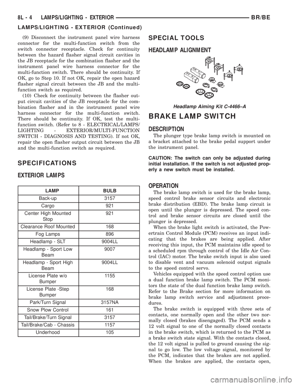
SPECIAL TOOLS
HEADLAMP ALIGNMENT
BRAKE LAMP SWITCH
DESCRIPTION
The plunger type brake lamp switch is mounted on
a bracket attached to the brake pedal support under
the instrument panel.
CAUTION: The switch can only be adjusted during
initial installation. If the switch is not adjusted prop-
erly a new switch must be installed.
OPERATION
The brake lamp switch is used for the brake lamp,
speed control brake sensor circuits and electronic
brake distribution (EBD). The brake lamp circuit is
open until the plunger is depressed. The speed con-
trol and brake sensor circuits are closed until the
plunger is depressed.
When the brake light switch is activated, the Pow-
ertrain Control Module (PCM) receives an input indi-
cating that the brakes are being applied. After
receiving this input, the PCM maintains idle speed to
a scheduled rpm through control of the Idle Air Con-
trol (IAC) motor. The brake switch input is also used
to disable vent and vacuum solenoid output signals
to the speed control servo.
Vehicles equipped with the speed control option use
a dual function brake lamp switch. The PCM moni-
tors the state of the dual function brake lamp switch.
Refer to the Brake section for more information on
brake lamp switch service and adjustment proce-
dures.
The brake switch is equipped with three sets of
contacts, one normally open and the other two nor-
mally closed (brakes disengaged). The PCM sends a
12 volt signal to one of the normally closed contacts
in the brake switch, which is returned to the PCM as
a brake switch state signal. With the contacts closed,
the 12 volt signal is pulled to ground causing the sig-
nal to go low. The low voltage signal, monitored by
the PCM, indicates that the brakes are not applied.
When the brakes are applied, the contacts open,
Headlamp Aiming Kit C-4466±A
8L - 4 LAMPS/LIGHTING - EXTERIORBR/BE
LAMPS/LIGHTING - EXTERIOR (Continued)
Page 604 of 2889
COMBINATION FLASHER
DESCRIPTION
The combination flasher is located in the Junction
Block (JB) behind the fuse access panel on the left
outboard end of the instrument panel. The combina-
tion flasher is a smart relay that functions as both
the turn signal system and the hazard warning sys-
tem flasher. The combination flasher contains active
electronic Integrated Circuitry (IC) elements. This
flasher is designed to handle the current flow
requirements of the factory-installed lighting. If sup-
plemental lighting is added to the turn signal lamp
circuits, such as when towing a trailer with lights,
the combination flasher will automatically try to
compensate to keep the flash rate the same.
The combination flasher has five blade-type termi-
nals that connect it to the vehicle electrical system
through five matching cavities in the receptacle of
the JB. While the combination flasher has a Interna-
tional Standards Organization (ISO)-type relay ter-
minal configuration or footprint, the internal
circuitry is much different. The combination flasher
does not use standard ISO-relay inputs or provide
ISO-relay type outputs or functions. The combination
flasher should never be substituted for an ISO-relay
or replaced with an ISO-relay, or else component and
vehicle damage may occur.
The combination flasher cannot be repaired or
adjusted and, if faulty or damaged, it must be
replaced.
OPERATION
The combination flasher has five blade-type termi-
nals intended for the following inputs and outputs:
fused B(+), fused ignition switch output, ground, turn
signal circuit, and hazard warning circuit. Constant
battery voltage and ground are supplied to the
flasher so that it can perform the hazard warning
function, and ignition switched battery voltage is
supplied for the turn signal function.
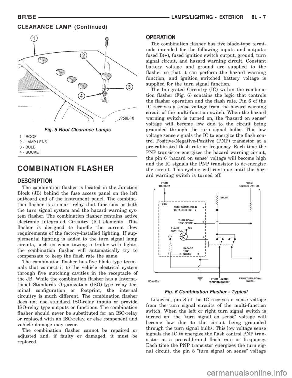
The Integrated Circuitry (IC) within the combina-
tion flasher (Fig. 6) contains the logic that controls
the flasher operation and the flash rate. Pin 6 of the
IC receives a sense voltage from the hazard warning
circuit of the multi-function switch. When the hazard
warning switch is turned on, the9hazard on sense9
voltage will become low due to the circuit being
grounded through the turn signal bulbs. This low
voltage sense signals the IC to energize the flash con-
trol Positive-Negative-Positive (PNP) transistor at a
pre-calibrated flash rate or frequency. Each time the
PNP transistor energizes the hazard warning circuit,
the pin 69hazard on sense9voltage will become high
and the IC signals the PNP transistor to de-energize
the circuit. This cycling will continue until the haz-
ard warning switch is turned off.
Likewise, pin 8 of the IC receives a sense voltage
from the turn signal circuits of the multi-function
switch. When the left or right turn signal switch is
turned on, the9turn signal on sense9voltage will
become low due to the circuit being grounded
through the turn signal bulbs. This low voltage sense
signals the IC to energize the flash control PNP tran-
sistor at a pre-calibrated flash rate or frequency.
Each time the PNP transistor energizes the turn sig-
nal circuit, the pin 89turn signal on sense9voltage
Fig. 5 Roof Clearance Lamps
1 - ROOF
2 - LAMP LENS
3 - BULB
4 - SOCKET
Fig. 6 Combination Flasher - Typical
BR/BELAMPS/LIGHTING - EXTERIOR 8L - 7
CLEARANCE LAMP (Continued)
Page 620 of 2889
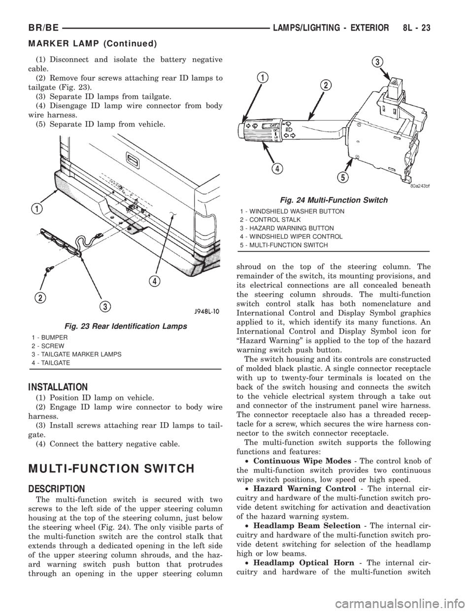
(1) Disconnect and isolate the battery negative
cable.
(2) Remove four screws attaching rear ID lamps to
tailgate (Fig. 23).
(3) Separate ID lamps from tailgate.
(4) Disengage ID lamp wire connector from body
wire harness.
(5) Separate ID lamp from vehicle.
INSTALLATION
(1) Position ID lamp on vehicle.
(2) Engage ID lamp wire connector to body wire
harness.
(3) Install screws attaching rear ID lamps to tail-
gate.
(4) Connect the battery negative cable.
MULTI-FUNCTION SWITCH
DESCRIPTION
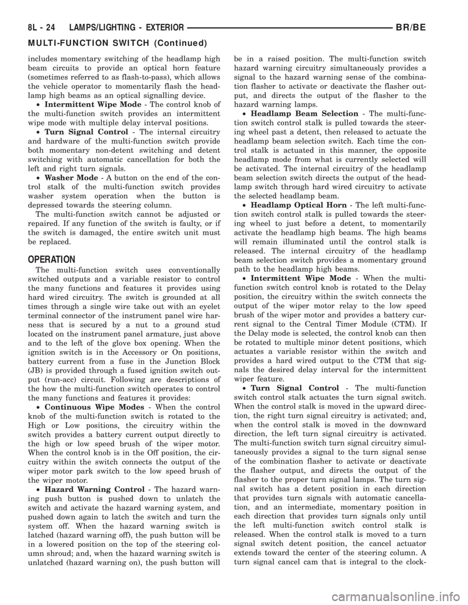
The multi-function switch is secured with two
screws to the left side of the upper steering column
housing at the top of the steering column, just below
the steering wheel (Fig. 24). The only visible parts of
the multi-function switch are the control stalk that
extends through a dedicated opening in the left side
of the upper steering column shrouds, and the haz-
ard warning switch push button that protrudes
through an opening in the upper steering columnshroud on the top of the steering column. The
remainder of the switch, its mounting provisions, and
its electrical connections are all concealed beneath
the steering column shrouds. The multi-function
switch control stalk has both nomenclature and
International Control and Display Symbol graphics
applied to it, which identify its many functions. An
International Control and Display Symbol icon for
ªHazard Warningº is applied to the top of the hazard
warning switch push button.
The switch housing and its controls are constructed
of molded black plastic. A single connector receptacle
with up to twenty-four terminals is located on the
back of the switch housing and connects the switch
to the vehicle electrical system through a take out
and connector of the instrument panel wire harness.
The connector receptacle also has a threaded recep-
tacle for a screw, which secures the wire harness con-
nector to the switch connector receptacle.
The multi-function switch supports the following
functions and features:
²Continuous Wipe Modes- The control knob of
the multi-function switch provides two continuous
wipe switch positions, low speed or high speed.
²Hazard Warning Control- The internal cir-
cuitry and hardware of the multi-function switch pro-
vide detent switching for activation and deactivation
of the hazard warning system.
²Headlamp Beam Selection- The internal cir-
cuitry and hardware of the multi-function switch pro-
vide detent switching for selection of the headlamp
high or low beams.
²Headlamp Optical Horn- The internal cir-
cuitry and hardware of the multi-function switch
Fig. 23 Rear Identification Lamps
1 - BUMPER
2 - SCREW
3 - TAILGATE MARKER LAMPS
4 - TAILGATE
Fig. 24 Multi-Function Switch
1 - WINDSHIELD WASHER BUTTON
2 - CONTROL STALK
3 - HAZARD WARNING BUTTON
4 - WINDSHIELD WIPER CONTROL
5 - MULTI-FUNCTION SWITCH
BR/BELAMPS/LIGHTING - EXTERIOR 8L - 23
MARKER LAMP (Continued)
Page 621 of 2889
includes momentary switching of the headlamp high
beam circuits to provide an optical horn feature
(sometimes referred to as flash-to-pass), which allows
the vehicle operator to momentarily flash the head-
lamp high beams as an optical signalling device.
²Intermittent Wipe Mode- The control knob of
the multi-function switch provides an intermittent
wipe mode with multiple delay interval positions.
²Turn Signal Control- The internal circuitry
and hardware of the multi-function switch provide
both momentary non-detent switching and detent
switching with automatic cancellation for both the
left and right turn signals.
²Washer Mode- A button on the end of the con-
trol stalk of the multi-function switch provides
washer system operation when the button is
depressed towards the steering column.
The multi-function switch cannot be adjusted or
repaired. If any function of the switch is faulty, or if
the switch is damaged, the entire switch unit must
be replaced.
OPERATION
The multi-function switch uses conventionally
switched outputs and a variable resistor to control
the many functions and features it provides using
hard wired circuitry. The switch is grounded at all
times through a single wire take out with an eyelet
terminal connector of the instrument panel wire har-
ness that is secured by a nut to a ground stud
located on the instrument panel armature, just above
and to the left of the glove box opening. When the
ignition switch is in the Accessory or On positions,
battery current from a fuse in the Junction Block
(JB) is provided through a fused ignition switch out-
put (run-acc) circuit. Following are descriptions of
the how the multi-function switch operates to control
the many functions and features it provides:
²Continuous Wipe Modes- When the control
knob of the multi-function switch is rotated to the
High or Low positions, the circuitry within the
switch provides a battery current output directly to
the high or low speed brush of the wiper motor.
When the control knob is in the Off position, the cir-
cuitry within the switch connects the output of the
wiper motor park switch to the low speed brush of
the wiper motor.
²Hazard Warning Control- The hazard warn-
ing push button is pushed down to unlatch the
switch and activate the hazard warning system, and
pushed down again to latch the switch and turn the
system off. When the hazard warning switch is
latched (hazard warning off), the push button will be
in a lowered position on the top of the steering col-
umn shroud; and, when the hazard warning switch is
unlatched (hazard warning on), the push button willbe in a raised position. The multi-function switch
hazard warning circuitry simultaneously provides a
signal to the hazard warning sense of the combina-
tion flasher to activate or deactivate the flasher out-
put, and directs the output of the flasher to the
hazard warning lamps.
²Headlamp Beam Selection- The multi-func-
tion switch control stalk is pulled towards the steer-
ing wheel past a detent, then released to actuate the
headlamp beam selection switch. Each time the con-
trol stalk is actuated in this manner, the opposite
headlamp mode from what is currently selected will
be activated. The internal circuitry of the headlamp
beam selection switch directs the output of the head-
lamp switch through hard wired circuitry to activate
the selected headlamp beam.
²Headlamp Optical Horn- The left multi-func-
tion switch control stalk is pulled towards the steer-
ing wheel to just before a detent, to momentarily
activate the headlamp high beams. The high beams
will remain illuminated until the control stalk is
released. The internal circuitry of the headlamp
beam selection switch provides a momentary ground
path to the headlamp high beams.
²Intermittent Wipe Mode- When the multi-
function switch control knob is rotated to the Delay
position, the circuitry within the switch connects the
output of the wiper motor relay to the low speed
brush of the wiper motor and provides a battery cur-
rent signal to the Central Timer Module (CTM). If
the Delay mode is selected, the control knob can then
be rotated to multiple minor detent positions, which
actuates a variable resistor within the switch and
provides a hard wired output to the CTM that sig-
nals the desired delay interval for the intermittent
wiper feature.
²Turn Signal Control- The multi-function
switch control stalk actuates the turn signal switch.
When the control stalk is moved in the upward direc-
tion, the right turn signal circuitry is activated; and,
when the control stalk is moved in the downward
direction, the left turn signal circuitry is activated.
The multi-function switch turn signal circuitry simul-
taneously provides a signal to the turn signal sense
of the combination flasher to activate or deactivate
the flasher output, and directs the output of the
flasher to the proper turn signal lamps. The turn sig-
nal switch has a detent position in each direction
that provides turn signals with automatic cancella-
tion, and an intermediate, momentary position in
each direction that provides turn signals only until
the left multi-function switch control stalk is
released. When the control stalk is moved to a turn
signal switch detent position, the cancel actuator
extends toward the center of the steering column. A
turn signal cancel cam that is integral to the clock-
8L - 24 LAMPS/LIGHTING - EXTERIORBR/BE
MULTI-FUNCTION SWITCH (Continued)