shaft DODGE RAM 2001 Service Owner's Guide
[x] Cancel search | Manufacturer: DODGE, Model Year: 2001, Model line: RAM, Model: DODGE RAM 2001Pages: 2889, PDF Size: 68.07 MB
Page 106 of 2889
REMOVAL
(1) Disconnect the vacuum and wiring connector
from the shift housing.
(2) Remove indicator switch.
(3) Remove shift motor housing cover, gasket and
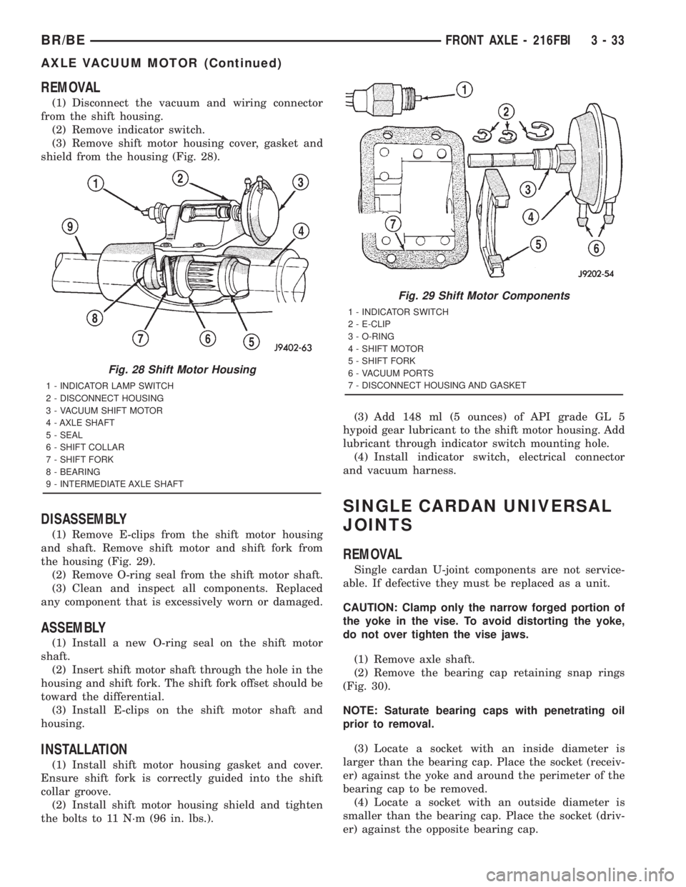
shield from the housing (Fig. 28).
DISASSEMBLY
(1) Remove E-clips from the shift motor housing
and shaft. Remove shift motor and shift fork from
the housing (Fig. 29).
(2) Remove O-ring seal from the shift motor shaft.
(3) Clean and inspect all components. Replaced
any component that is excessively worn or damaged.
ASSEMBLY
(1) Install a new O-ring seal on the shift motor
shaft.
(2) Insert shift motor shaft through the hole in the
housing and shift fork. The shift fork offset should be
toward the differential.
(3) Install E-clips on the shift motor shaft and
housing.
INSTALLATION
(1) Install shift motor housing gasket and cover.
Ensure shift fork is correctly guided into the shift
collar groove.
(2) Install shift motor housing shield and tighten
the bolts to 11 N´m (96 in. lbs.).(3) Add 148 ml (5 ounces) of API grade GL 5
hypoid gear lubricant to the shift motor housing. Add
lubricant through indicator switch mounting hole.
(4) Install indicator switch, electrical connector
and vacuum harness.
SINGLE CARDAN UNIVERSAL
JOINTS
REMOVAL
Single cardan U-joint components are not service-
able. If defective they must be replaced as a unit.
CAUTION: Clamp only the narrow forged portion of
the yoke in the vise. To avoid distorting the yoke,
do not over tighten the vise jaws.
(1) Remove axle shaft.
(2) Remove the bearing cap retaining snap rings
(Fig. 30).
NOTE: Saturate bearing caps with penetrating oil
prior to removal.
(3) Locate a socket with an inside diameter is
larger than the bearing cap. Place the socket (receiv-
er) against the yoke and around the perimeter of the
bearing cap to be removed.
(4) Locate a socket with an outside diameter is
smaller than the bearing cap. Place the socket (driv-
er) against the opposite bearing cap.
Fig. 28 Shift Motor Housing
1 - INDICATOR LAMP SWITCH
2 - DISCONNECT HOUSING
3 - VACUUM SHIFT MOTOR
4 - AXLE SHAFT
5 - SEAL
6 - SHIFT COLLAR
7 - SHIFT FORK
8 - BEARING
9 - INTERMEDIATE AXLE SHAFT
Fig. 29 Shift Motor Components
1 - INDICATOR SWITCH
2 - E-CLIP
3 - O-RING
4 - SHIFT MOTOR
5 - SHIFT FORK
6 - VACUUM PORTS
7 - DISCONNECT HOUSING AND GASKET
BR/BEFRONT AXLE - 216FBI 3 - 33
AXLE VACUUM MOTOR (Continued)
Page 107 of 2889
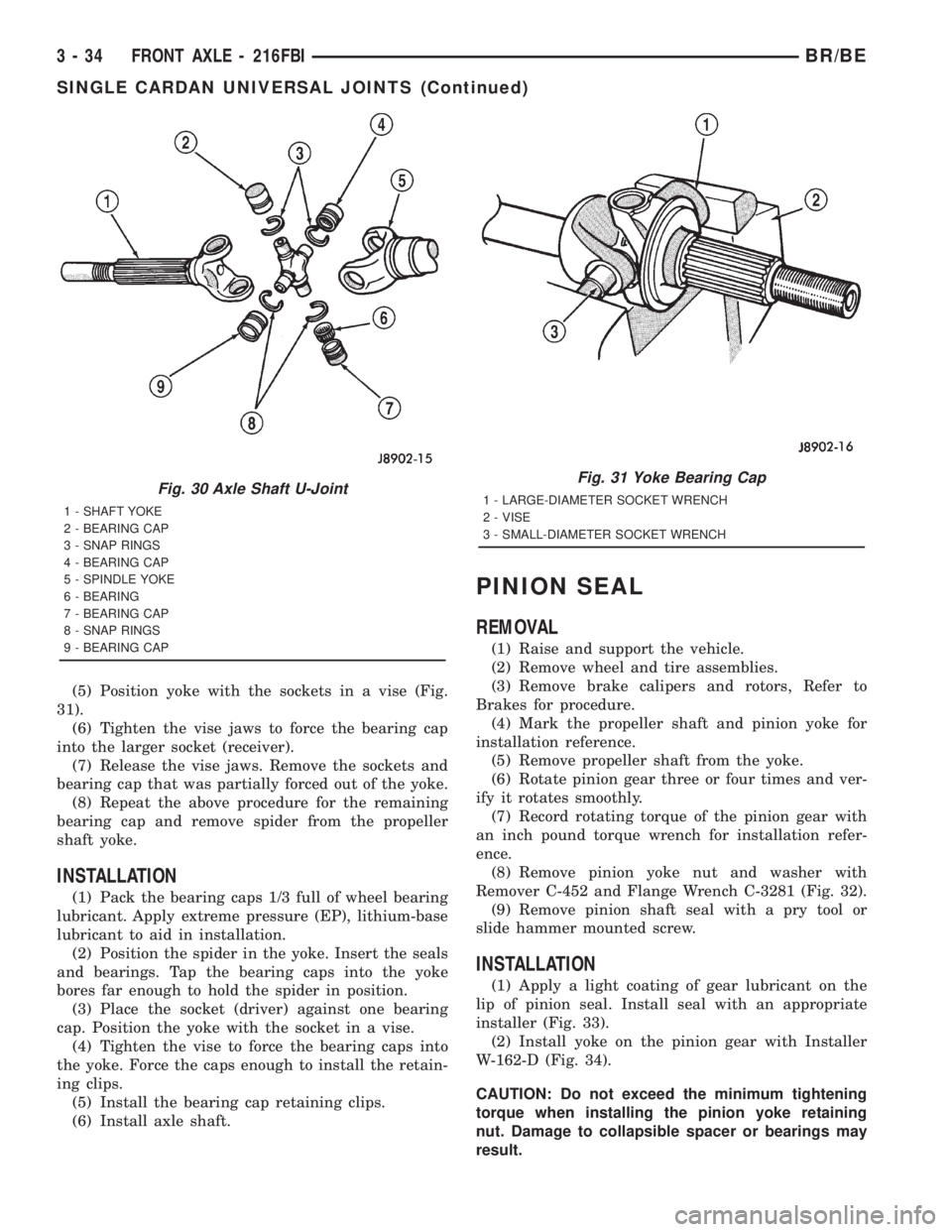
(5) Position yoke with the sockets in a vise (Fig.
31).
(6) Tighten the vise jaws to force the bearing cap
into the larger socket (receiver).
(7) Release the vise jaws. Remove the sockets and
bearing cap that was partially forced out of the yoke.
(8) Repeat the above procedure for the remaining
bearing cap and remove spider from the propeller
shaft yoke.
INSTALLATION
(1) Pack the bearing caps 1/3 full of wheel bearing
lubricant. Apply extreme pressure (EP), lithium-base
lubricant to aid in installation.
(2) Position the spider in the yoke. Insert the seals
and bearings. Tap the bearing caps into the yoke
bores far enough to hold the spider in position.
(3) Place the socket (driver) against one bearing
cap. Position the yoke with the socket in a vise.
(4) Tighten the vise to force the bearing caps into
the yoke. Force the caps enough to install the retain-
ing clips.
(5) Install the bearing cap retaining clips.
(6) Install axle shaft.
PINION SEAL
REMOVAL
(1) Raise and support the vehicle.
(2) Remove wheel and tire assemblies.
(3) Remove brake calipers and rotors, Refer to
Brakes for procedure.
(4) Mark the propeller shaft and pinion yoke for
installation reference.
(5) Remove propeller shaft from the yoke.
(6) Rotate pinion gear three or four times and ver-
ify it rotates smoothly.
(7) Record rotating torque of the pinion gear with
an inch pound torque wrench for installation refer-
ence.
(8) Remove pinion yoke nut and washer with
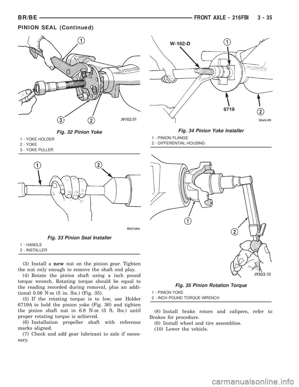
Remover C-452 and Flange Wrench C-3281 (Fig. 32).
(9) Remove pinion shaft seal with a pry tool or
slide hammer mounted screw.
INSTALLATION
(1) Apply a light coating of gear lubricant on the
lip of pinion seal. Install seal with an appropriate
installer (Fig. 33).
(2) Install yoke on the pinion gear with Installer
W-162-D (Fig. 34).
CAUTION: Do not exceed the minimum tightening
torque when installing the pinion yoke retaining
nut. Damage to collapsible spacer or bearings may
result.
Fig. 30 Axle Shaft U-Joint
1 - SHAFT YOKE
2 - BEARING CAP
3 - SNAP RINGS
4 - BEARING CAP
5 - SPINDLE YOKE
6 - BEARING
7 - BEARING CAP
8 - SNAP RINGS
9 - BEARING CAP
Fig. 31 Yoke Bearing Cap
1 - LARGE-DIAMETER SOCKET WRENCH
2 - VISE
3 - SMALL-DIAMETER SOCKET WRENCH
3 - 34 FRONT AXLE - 216FBIBR/BE
SINGLE CARDAN UNIVERSAL JOINTS (Continued)
Page 108 of 2889
(3) Install anewnut on the pinion gear. Tighten
the nut only enough to remove the shaft end play.
(4) Rotate the pinion shaft using a inch pound
torque wrench. Rotating torque should be equal to
the reading recorded during removal, plus an addi-
tional 0.56 N´m (5 in. lbs.) (Fig. 35).
(5) If the rotating torque is to low, use Holder
6719A to hold the pinion yoke (Fig. 36) and tighten
the pinion shaft nut in 6.8 N´m (5 ft. lbs.) until
proper rotating torque is achieved.
(6) Installation propeller shaft with reference
marks aligned.
(7) Check and add gear lubricant to axle if neces-
sary.(8) Install brake rotors and calipers, refer to
Brakes for procedure.
(9) Install wheel and tire assemblies.
(10) Lower the vehicle.
Fig. 32 Pinion Yoke
1 - YOKE HOLDER
2 - YOKE
3 - YOKE PULLER
Fig. 33 Pinion Seal Installer
1 - HANDLE
2 - INSTALLER
Fig. 34 Pinion Yoke Installer
1 - PINION FLANGE
2 - DIFFERENTIAL HOUSING
Fig. 35 Pinion Rotation Torque
1 - PINION YOKE
2 - INCH POUND TORQUE WRENCH
BR/BEFRONT AXLE - 216FBI 3 - 35
PINION SEAL (Continued)
Page 109 of 2889
DIFFERENTIAL
REMOVAL
(1) Raise and support vehicle.
(2) Remove lubricant fill hole plug from the differ-
ential housing cover.
(3) Remove differential housing cover and drain
the lubricant from the housing.
(4) Clean the housing cavity with a flushing oil,
light engine oil or lint free cloth.Do not use water,
steam, kerosene or gasoline for cleaning.
(5) Remove hub bearings and axle shafts.
(6) Note the installation reference letters stamped
on the bearing caps and housing machined sealing
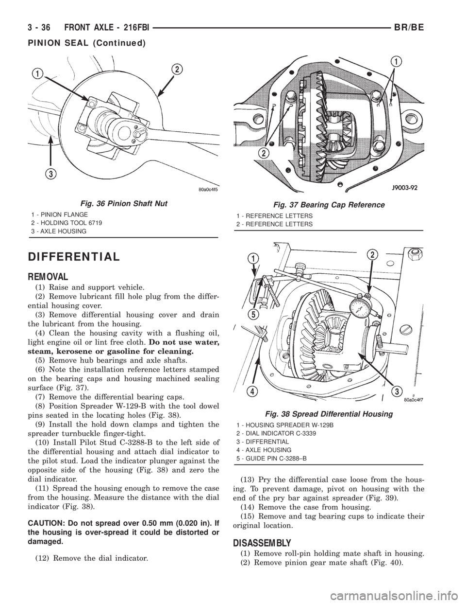
surface (Fig. 37).
(7) Remove the differential bearing caps.
(8) Position Spreader W-129-B with the tool dowel
pins seated in the locating holes (Fig. 38).
(9) Install the hold down clamps and tighten the
spreader turnbuckle finger-tight.
(10) Install Pilot Stud C-3288-B to the left side of
the differential housing and attach dial indicator to
the pilot stud. Load the indicator plunger against the
opposite side of the housing (Fig. 38) and zero the
dial indicator.
(11) Spread the housing enough to remove the case
from the housing. Measure the distance with the dial
indicator (Fig. 38).
CAUTION: Do not spread over 0.50 mm (0.020 in). If
the housing is over-spread it could be distorted or
damaged.
(12) Remove the dial indicator.(13) Pry the differential case loose from the hous-
ing. To prevent damage, pivot on housing with the
end of the pry bar against spreader (Fig. 39).
(14) Remove the case from housing.
(15) Remove and tag bearing cups to indicate their
original location.
DISASSEMBLY
(1) Remove roll-pin holding mate shaft in housing.
(2) Remove pinion gear mate shaft (Fig. 40).
Fig. 36 Pinion Shaft Nut
1 - PINION FLANGE
2 - HOLDING TOOL 6719
3 - AXLE HOUSING
Fig. 37 Bearing Cap Reference
1 - REFERENCE LETTERS
2 - REFERENCE LETTERS
Fig. 38 Spread Differential Housing
1 - HOUSING SPREADER W-129B
2 - DIAL INDICATOR C-3339
3 - DIFFERENTIAL
4 - AXLE HOUSING
5 - GUIDE PIN C-3288±B
3 - 36 FRONT AXLE - 216FBIBR/BE
PINION SEAL (Continued)
Page 110 of 2889

(3) Rotate the differential side gears and remove
the pinion mate gears and thrust washers (Fig. 41).
(4) Remove the differential side gears and thrust
washers.ASSEMBLY
(1) Install the differential side gears and thrust
washers.
(2) Install the pinion mate gears and thrust wash-
ers.
(3) Install the pinion gear mate shaft.
(4) Align the hole in the pinion gear mate shaft
with the hole in the differential case.
(5) Install and seat the pinion mate shaft roll-pin
in the differential case and mate shaft with a punch
and hammer (Fig. 42). Peen the edge of the roll-pin
hole in the differential case slightly in two places,
180É apart.
(6) Lubricate all differential components with
hypoid gear lubricant.
INSTALLATION
NOTE: If replacement differential bearings or differ-
ential case are being installed, differential side
bearing shim requirements may change. Refer to
Adjustments (Differential Bearing Preload and Gear
Backlash) procedures to determine proper shim
selection.
(1) Position Spreader W-129-B with the tool dowel
pins seated in the locating holes. Install the hold
down clamps and tighten the tool turnbuckle finger-
tight.
Fig. 39 Differential Removal
1 - DIFFERENTIAL
2-PRYBAR
Fig. 40 Pinion Mate Shaft
1 - PINION MATE GEAR
2 - PINION MATE SHAFT
3 - SIDE GEAR
4 - DRIFT
Fig. 41 Pinion Mate/Side Gear
1 - THRUST WASHER
2 - SIDE GEAR
3 - PINION MATE GEAR
BR/BEFRONT AXLE - 216FBI 3 - 37
DIFFERENTIAL (Continued)
Page 111 of 2889
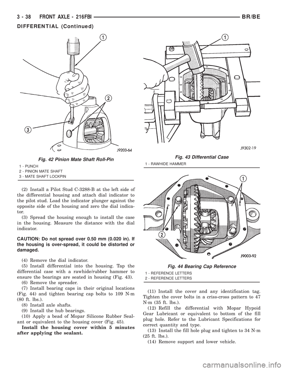
(2) Install a Pilot Stud C-3288-B at the left side of
the differential housing and attach dial indicator to
the pilot stud. Load the indicator plunger against the
opposite side of the housing and zero the dial indica-
tor.
(3) Spread the housing enough to install the case
in the housing. Measure the distance with the dial
indicator.
CAUTION: Do not spread over 0.50 mm (0.020 in). If
the housing is over-spread, it could be distorted or
damaged.
(4) Remove the dial indicator.
(5) Install differential into the housing. Tap the
differential case with a rawhide/rubber hammer to
ensure the bearings are seated in housing (Fig. 43).
(6) Remove the spreader.
(7) Install bearing caps in their original locations
(Fig. 44) and tighten bearing cap bolts to 109 N´m
(80 ft. lbs.).
(8) Install axle shafts.
(9) Install the hub bearings.
(10) Apply a bead of Mopar Silicone Rubber Seal-
ant or equivalent to the housing cover (Fig. 45).
Install the housing cover within 5 minutes
after applying the sealant.(11) Install the cover and any identification tag.
Tighten the cover bolts in a criss-cross pattern to 47
N´m (35 ft. lbs.).
(12) Refill the differential with Mopar Hypoid
Gear Lubricant or equivalent to bottom of the fill
plug hole. Refer to the Lubricant Specifications for
correct quantity and type.
(13) Install the fill hole plug and tighten to 34 N´m
(25 ft. lbs.).
(14) Remove support and lower vehicle.
Fig. 42 Pinion Mate Shaft Roll-Pin
1 - PUNCH
2 - PINION MATE SHAFT
3 - MATE SHAFT LOCKPIN
Fig. 43 Differential Case
1 - RAWHIDE HAMMER
Fig. 44 Bearing Cap Reference
1 - REFERENCE LETTERS
2 - REFERENCE LETTERS
3 - 38 FRONT AXLE - 216FBIBR/BE
DIFFERENTIAL (Continued)
Page 113 of 2889

PINION GEAR/RING GEAR
REMOVAL
NOTE: The ring and pinion gears are serviced as a
matched set. Never replace one gear without replac-
ing the other gear.
(1) Raise and support the vehcile.
(2) Mark pinion yoke and propeller shaft for
installation reference.
(3) Disconnect propeller shaft from pinion yoke
and tie propeller shaft to underbody.
(4) Remove differential from the housing.
(5) Secure differential case in a vise with soft
metal jaw.
(6) Remove ring gear bolts from the differential
case.
(7) Drive ring gear off the differential case with a
rawhide hammer (Fig. 48).
(8) Hold yoke with Holder 6719A and remove pin-
ion nut and washer.
(9) Remove pinion yoke from the pinion shaft with
Puller C-452 and Flange Wrench C-3281 (Fig. 49).
(10) Remove pinion gear from housing (Fig. 50).
(11) Remove pinion seal with a pry bar or slide
hammer mounted screw.(12) Remove front pinion bearing and oil slinger.
(13) Remove front pinion bearing cup with
Remover D-147 and Handle C-4171 (Fig. 51).
(14) Remove rear bearing cup (Fig. 52) with
Remover D-149 and Handle C-4171.
(15) Remove collapsible preload spacer from pinion
shaft (Fig. 53).
(16) Remove rear pinion bearing with Puller
C-293-PA and Adapters C-293-40 (Fig. 54).
(17) Remove pinion depth shims from pinion shaft
and record thickness.
Fig. 47 Differential Bearing Installer
1 - HANDLE
2 - DIFFERENTIAL
3 - BEARING
4 - INSTALLER
Fig. 48 Ring Gear
1 - CASE
2 - RING GEAR
3- HAMMER
Fig. 49 Pinion Yoke
1 - YOKE HOLDER
2 - YOKE
3 - YOKE PULLER
3 - 40 FRONT AXLE - 216FBIBR/BE
DIFFERENTIAL CASE BEARINGS (Continued)
Page 115 of 2889

INSTALLATION
NOTE: Pinion depth shims are placed between the
rear pinion bearing cone and pinion gear to achieve
proper ring and pinion gear mesh. If ring and pinion
gears are reused, the original pinion depth shim
can be used. Refer to Adjustments (Pinion Gear
Depth) to select the proper shim thickness if ring
and pinion gears are replaced.
(1) Apply Mopar Door Ease stick lubricant to out-
side surface of bearing cups.
(2) Install rear pinion bearing cup with Installer
D-146 and Handle C-4171 (Fig. 55) and verify cup is
seated.
(3) Install front pinion bearing cup with Installer
D-144 and Handle C±4171 (Fig. 56) and verify cup is
seated.
(4) Install pinion front bearing, oil slinger. Apply a
light coating of gear lubricant on the lip of pinion
seal.
Fig. 54 Rear Pinion Bearing
1 - PULLER
2 - VISE
3 - ADAPTERS
4 - PINION SHAFTFig. 55 Rear Pinion Bearing Cup
1 - INSTALLER
2 - HANDLE
Fig. 56 Front Pinion Bearing Cup
1 - INSTALLER
2 - HANDLE
3 - 42 FRONT AXLE - 216FBIBR/BE
PINION GEAR/RING GEAR (Continued)
Page 116 of 2889

(5) Install pinion seal with an appropriate installer
(Fig. 57).
(6) Install proper thickness depth shim on the pin-
ion gear.
(7) Install rear bearing and oil slinger, if equipped
on pinion gear with Installer W-262 (Fig. 58).
(8) Install a new collapsible preload spacer on pin-
ion shaft (Fig. 59).
(9) Install pinion gear in housing.
(10) Install yoke with Installer W-162-D and Yoke
Holder 6719A (Fig. 60).
Fig. 57 Pinion Seal Installer
1 - HANDLE
2 - INSTALLER
Fig. 58 Rear Pinion Bearing
1 - PRESS
2 - INSTALLER
3 - PINION GEAR
4 - PINION BEARING
Fig. 59 Collapsible Preload Spacer
1 - COLLAPSIBLE SPACER
2 - SHOULDER
3 - PINION GEAR
4 - OIL SLINGER
5 - REAR PINION BEARING
Fig. 60 Pinion Yoke Installer
1 - INSTALLER
2 - YOKE HOLDER
BR/BEFRONT AXLE - 216FBI 3 - 43
PINION GEAR/RING GEAR (Continued)
Page 117 of 2889

(11) Install yoke washer and anewnut on the
pinion gear. Tighten the nut to 258 N´m (190 ft. lbs.)
minimum.Do not over-tighten.Maximum torque is
393 N´m (290 ft. lbs.).
CAUTION: Never loosen pinion gear nut to decrease
pinion gear bearing preload torque and never
exceed specified preload torque. If preload torque
is exceeded a new collapsible spacer must be
installed.
(12) Use Yoke Holder 6719A to hold the yoke (Fig.
61) and tighten the nut in 6.8 N´m (5 ft. lbs.) until
the rotating torque is achieved. Measure the preload
torque frequently to avoid over-tightening the nut.
(13) Check bearing preload torque with an inch
pound torque wrench (Fig. 62). The torque necessary
to rotate the pinion gear should be:
²Original Bearings: 1 to 3 N´m (10 to 20 in. lbs.).
²New Bearings: 2 to 5 N´m (15 to 35 in. lbs.).
(14) Invert differential case in a vise and start two
ring gear bolts. This will provide case-to-ring gear
bolt hole alignment.
(15) Installnewring gear bolts and alternately
tighten to 108 N´m (80 ft. lbs.). (Fig. 63).
CAUTION: Do not reuse the bolts that held the ring
gear to the differential case. The bolts can fracture
causing extensive damage.
(16) Install differential in axle housing and verify
gear mesh and contact pattern. Refer to Adjustments
(Gear Contact Pattern).
(17) Install differential cover and fill with lubri-
cant.(18) Install propeller shaft with reference marks
aligned.
(19) Remove support and lower vehicle.
Fig. 61 Tightening Pinion Nut
1 - PINION FLANGE
2 - YOKE HOLDING
3 - DIFFERENTIAL HOUSING
Fig. 62 Pinion Rotating Torque
1 - PINION YOKE
2 - INCH POUND TORQUE WRENCH
Fig. 63 Ring Gear Bolt
1 - TORQUE WRENCH
2 - RING GEAR BOLT
3 - RING GEAR
4 - CASE
3 - 44 FRONT AXLE - 216FBIBR/BE
PINION GEAR/RING GEAR (Continued)