seat adjustment DODGE RAM 2001 Service Service Manual
[x] Cancel search | Manufacturer: DODGE, Model Year: 2001, Model line: RAM, Model: DODGE RAM 2001Pages: 2889, PDF Size: 68.07 MB
Page 2153 of 2889

CAUTION: If the condition of the transmission
before the overhaul procedure caused excessive
metallic or fiber contamination in the fluid, replace
the torque converter and reverse flush the cooler(s)
and cooler lines. Fluid contamination and transmis-
sion failure can result if not done.
(7) Install torque converter. Use C-clamp or metal
strap to hold converter in place for installation.
BAND ADJUSTMENT AND FINAL
(1) Adjust front and rear bands as follows:
(a) Loosen locknut on each band adjusting screw
4-5 turns.
(b) Tighten both adjusting screws to 8 N´m (72
in. lbs.).
(c) Back off front band adjusting screw 2-7/8
turns.
(d) Back off rear band adjusting screw 2 turns.
(e) Hold each adjusting screw in position and
tighten locknut to 34 N´m (25 ft. lbs.) torque.(2) Install magnet in oil pan. Magnet seats on
small protrusion at corner of pan.
(3) Position new oil pan gasket on case and install
oil pan. Tighten pan bolts to 17 N´m (13 ft. lbs.).
(4) Install throttle valve and shift selector levers
on valve body manual lever shaft.
(5) Apply small quantity of dielectric grease to ter-
minal pins of solenoid case connector and neutral
switch.
(6) Fill transmission with recommended fluid.
Refer to Service Procedures section of this group.
INSTALLATION
(1) Check torque converter hub and hub drive
notches for sharp edges burrs, scratches, or nicks.
Polish the hub and notches with 320/400 grit paper
and crocus cloth if necessary. The hub must be
smooth to avoid damaging pump seal at installation.
(2) Lubricate pocket in the rear oil pump seal lip
with transmission fluid.
(3) Lubricate converter pilot hub of the crankshaft
with a light coating of MopartHigh Temp Grease.
(4) Align and install converter in oil pump.
(5) Carefully insert converter in oil pump. Then
rotate converter back and forth until fully seated in
pump gears.
(6) Check converter seating with steel scale and
straightedge (Fig. 65). Surface of converter lugs
should be 1/2 in. to rear of straightedge when con-
verter is fully seated.
(7) Temporarily secure converter with C-clamp.
Fig. 63 Accumulator Piston And Springs
1 - ACCUMULATOR PISTON
2 - OUTER SPRING
3 - INNER SPRING
Fig. 64 Manual Lever Shaft Seal
1 - 15/16©© SOCKET
2 - SEAL
Fig. 65 Checking Converter Seating - Typical
1 - SCALE
2 - STRAIGHTEDGE
21 - 518 AUTOMATIC TRANSMISSION - 46REBR/BE
AUTOMATIC TRANSMISSION - 46RE (Continued)
Page 2280 of 2889
(17) Perform Line Pressure and Throttle Pressure
adjustments. (Refer to 21 - TRANSMISSION/TRAN-
SAXLE/AUTOMATIC/VALVE BODY - ADJUST-
MENTS)
(18) Lubricate solenoid case connector O-rings and
shaft of manual lever with light coat of petroleum
jelly.
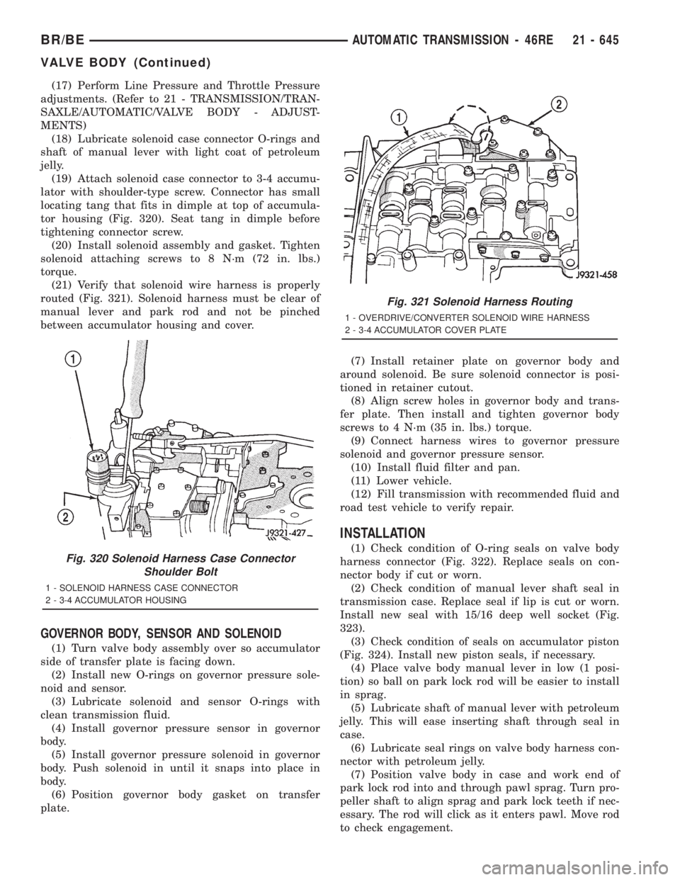
(19) Attach solenoid case connector to 3-4 accumu-
lator with shoulder-type screw. Connector has small
locating tang that fits in dimple at top of accumula-
tor housing (Fig. 320). Seat tang in dimple before
tightening connector screw.
(20) Install solenoid assembly and gasket. Tighten
solenoid attaching screws to 8 N´m (72 in. lbs.)
torque.
(21) Verify that solenoid wire harness is properly
routed (Fig. 321). Solenoid harness must be clear of
manual lever and park rod and not be pinched
between accumulator housing and cover.
GOVERNOR BODY, SENSOR AND SOLENOID
(1) Turn valve body assembly over so accumulator
side of transfer plate is facing down.
(2) Install new O-rings on governor pressure sole-
noid and sensor.
(3) Lubricate solenoid and sensor O-rings with
clean transmission fluid.
(4) Install governor pressure sensor in governor
body.
(5) Install governor pressure solenoid in governor
body. Push solenoid in until it snaps into place in
body.
(6) Position governor body gasket on transfer
plate.(7) Install retainer plate on governor body and
around solenoid. Be sure solenoid connector is posi-
tioned in retainer cutout.
(8) Align screw holes in governor body and trans-
fer plate. Then install and tighten governor body
screws to 4 N´m (35 in. lbs.) torque.
(9) Connect harness wires to governor pressure
solenoid and governor pressure sensor.
(10) Install fluid filter and pan.
(11) Lower vehicle.
(12) Fill transmission with recommended fluid and
road test vehicle to verify repair.
INSTALLATION
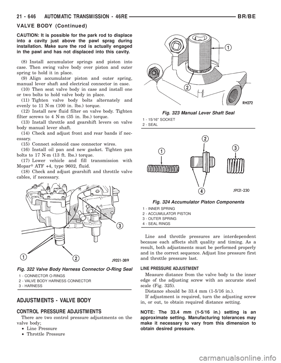
(1) Check condition of O-ring seals on valve body
harness connector (Fig. 322). Replace seals on con-
nector body if cut or worn.
(2) Check condition of manual lever shaft seal in
transmission case. Replace seal if lip is cut or worn.
Install new seal with 15/16 deep well socket (Fig.
323).
(3) Check condition of seals on accumulator piston
(Fig. 324). Install new piston seals, if necessary.
(4) Place valve body manual lever in low (1 posi-
tion) so ball on park lock rod will be easier to install
in sprag.
(5) Lubricate shaft of manual lever with petroleum
jelly. This will ease inserting shaft through seal in
case.
(6) Lubricate seal rings on valve body harness con-
nector with petroleum jelly.
(7) Position valve body in case and work end of
park lock rod into and through pawl sprag. Turn pro-
peller shaft to align sprag and park lock teeth if nec-
essary. The rod will click as it enters pawl. Move rod
to check engagement.Fig. 320 Solenoid Harness Case Connector
Shoulder Bolt
1 - SOLENOID HARNESS CASE CONNECTOR
2 - 3-4 ACCUMULATOR HOUSING
Fig. 321 Solenoid Harness Routing
1 - OVERDRIVE/CONVERTER SOLENOID WIRE HARNESS
2 - 3-4 ACCUMULATOR COVER PLATE
BR/BEAUTOMATIC TRANSMISSION - 46RE 21 - 645
VALVE BODY (Continued)
Page 2281 of 2889
CAUTION: It is possible for the park rod to displace
into a cavity just above the pawl sprag during
installation. Make sure the rod is actually engaged
in the pawl and has not displaced into this cavity.
(8) Install accumulator springs and piston into
case. Then swing valve body over piston and outer
spring to hold it in place.
(9) Align accumulator piston and outer spring,
manual lever shaft and electrical connector in case.
(10) Then seat valve body in case and install one
or two bolts to hold valve body in place.
(11) Tighten valve body bolts alternately and
evenly to 11 N´m (100 in. lbs.) torque.
(12) Install new fluid filter on valve body. Tighten
filter screws to 4 N´m (35 in. lbs.) torque.
(13) Install throttle and gearshift levers on valve
body manual lever shaft.
(14) Check and adjust front and rear bands if nec-
essary.
(15) Connect solenoid case connector wires.
(16) Install oil pan and new gasket. Tighten pan
bolts to 17 N´m (13 ft. lbs.) torque.
(17) Lower vehicle and fill transmission with
MopartATF +4, type 9602, fluid.
(18) Check and adjust gearshift and throttle valve
cables, if necessary.
ADJUSTMENTS - VALVE BODY
CONTROL PRESSURE ADJUSTMENTS
There are two control pressure adjustments on the
valve body;
²Line Pressure
²Throttle PressureLine and throttle pressures are interdependent
because each affects shift quality and timing. As a
result, both adjustments must be performed properly
and in the correct sequence. Adjust line pressure first
and throttle pressure last.
LINE PRESSURE ADJUSTMENT
Measure distance from the valve body to the inner
edge of the adjusting screw with an accurate steel
scale (Fig. 325).
Distance should be 33.4 mm (1-5/16 in.).
If adjustment is required, turn the adjusting screw
in, or out, to obtain required distance setting.
NOTE: The 33.4 mm (1-5/16 in.) setting is an
approximate setting. Manufacturing tolerances may
make it necessary to vary from this dimension to
obtain desired pressure.
Fig. 322 Valve Body Harness Connector O-Ring Seal
1 - CONNECTOR O-RINGS
2 - VALVE BODY HARNESS CONNECTOR
3 - HARNESS
Fig. 323 Manual Lever Shaft Seal
1 - 15/16©© SOCKET
2 - SEAL
Fig. 324 Accumulator Piston Components
1 - INNER SPRING
2 - ACCUMULATOR PISTON
3 - OUTER SPRING
4 - SEAL RINGS
21 - 646 AUTOMATIC TRANSMISSION - 46REBR/BE
VALVE BODY (Continued)
Page 2322 of 2889

INPUT SHAFT END PLAY CHECK
NOTE: Overdrive unit must be installed in order to
correctly measure the input shaft end-play.
(1) Measure input shaft end play (Fig. 56).
NOTE: If end play is incorrect, transmission is
incorrectly assembled, or reaction shaft thrust
washer is incorrect. The reaction shaft thrust
washer is selective.
(a) Attach Adapter 8266-5 to Handle 8266-8.
(b) Attach dial indicator C-3339 to Handle
8266-8.
(c) Install the assembled tool onto the input
shaft of the transmission and tighten the retaining
screw on Adapter 8266-5 to secure it to the input
shaft.
(d) Position the dial indicator plunger against a
flat spot on the oil pump and zero the dial indica-
tor.
(e) Move input shaft in and out and record read-
ing. End play should be 0.86 - 2.13 mm (0.034 -
0.084 in.). Adjust as necessary.
ACCUMULATOR, VALVE BODY, OIL PAN, AND
TORQUE CONVERTER
(1) Install accumulator inner spring, piston and
outer spring (Fig. 57).(2) Verify that park/neutral position switch has
notbeen installed in case. Valve body can not be
installed if switch is in position.
(3) Install new valve body manual shaft seal in
case (Fig. 58). Lubricate seal lip and manual shaft
with petroleum jelly. Start seal over shaft and into
case. Seat seal with 15/16 inch, deep well socket.
(4) Install valve body as follows:
(a) Start park rod into park pawl. If rod will not
slide past park pawl, pawl is engaged in park gear.
Rotate overdrive output shaft with suitable size 12
point socket; this will free pawl and allow rod to
engage.
(b) Align and seat valve body on case. Be sure
manual lever shaft and overdrive connector are
fully seated in case.
(c) Install and start all valve body attaching
bolts by hand. Then tighten bolts evenly, in a diag-
onal pattern to 12 N´m (105 in. lbs.) torque.Do
not overtighten valve body bolts. This could
result in distortion and cross leakage after
installation..
(5) Install new filter on valve body. Tighten filter
screws to 4 N´m (35 in. lbs.).
(6) Install seal on park/neutral position switch.
Then install and tighten switch to 34 N´m (25 ft.
lbs.).
CAUTION: If the condition of the transmission
before the overhaul procedure caused excessive
metallic or fiber contamination in the fluid, replace
the torque converter and reverse flush the cooler(s)
and cooler lines. Fluid contamination and transmis-
sion failure can result if not done.
(7) Install torque converter. Use C-clamp or metal
strap to hold converter in place for installation.
BAND ADJUSTMENT AND FINAL
(1) Adjust front and rear bands as follows:
Fig. 56 Checking Input Shaft End Play
1 - TOOL 8266-8
2 - TOOL 8266-5
3 - TOOL C-3339
Fig. 57 Accumulator Piston And Springs
1 - ACCUMULATOR PISTON
2 - OUTER SPRING
3 - INNER SPRING
BR/BEAUTOMATIC TRANSMISSION - 47RE 21 - 687
AUTOMATIC TRANSMISSION - 47RE (Continued)
Page 2452 of 2889
(11) Install manual valve.
(12) Install throttle valve and spring.
(13) Install kickdown valve and detent.
(14) Install pressure regulator valve.
(15) Install switch valve.
(16) Position adjusting screw bracket on valve
body. Align valve springs and press bracket into
place. Install short, upper bracket screws first and
long bottom screw last. Verify that valve springs and
bracket are properly aligned. Then tighten all three
bracket screws to 4 N´m (35 in. lbs.) torque.
(17) Perform Line Pressure and Throttle Pressure
adjustments. (Refer to 21 - TRANSMISSION/TRAN-
SAXLE/AUTOMATIC/VALVE BODY - ADJUST-
MENTS)
(18) Lubricate solenoid case connector O-rings and
shaft of manual lever with light coat of petroleum
jelly.
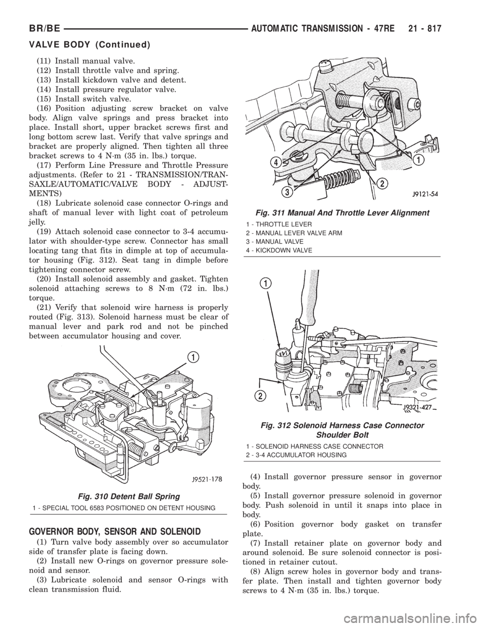
(19) Attach solenoid case connector to 3-4 accumu-
lator with shoulder-type screw. Connector has small
locating tang that fits in dimple at top of accumula-
tor housing (Fig. 312). Seat tang in dimple before
tightening connector screw.
(20) Install solenoid assembly and gasket. Tighten
solenoid attaching screws to 8 N´m (72 in. lbs.)
torque.
(21) Verify that solenoid wire harness is properly
routed (Fig. 313). Solenoid harness must be clear of
manual lever and park rod and not be pinched
between accumulator housing and cover.
GOVERNOR BODY, SENSOR AND SOLENOID
(1) Turn valve body assembly over so accumulator
side of transfer plate is facing down.
(2) Install new O-rings on governor pressure sole-
noid and sensor.
(3) Lubricate solenoid and sensor O-rings with
clean transmission fluid.(4) Install governor pressure sensor in governor
body.
(5) Install governor pressure solenoid in governor
body. Push solenoid in until it snaps into place in
body.
(6) Position governor body gasket on transfer
plate.
(7) Install retainer plate on governor body and
around solenoid. Be sure solenoid connector is posi-
tioned in retainer cutout.
(8) Align screw holes in governor body and trans-
fer plate. Then install and tighten governor body
screws to 4 N´m (35 in. lbs.) torque.
Fig. 310 Detent Ball Spring
1 - SPECIAL TOOL 6583 POSITIONED ON DETENT HOUSING
Fig. 311 Manual And Throttle Lever Alignment
1 - THROTTLE LEVER
2 - MANUAL LEVER VALVE ARM
3 - MANUAL VALVE
4 - KICKDOWN VALVE
Fig. 312 Solenoid Harness Case Connector
Shoulder Bolt
1 - SOLENOID HARNESS CASE CONNECTOR
2 - 3-4 ACCUMULATOR HOUSING
BR/BEAUTOMATIC TRANSMISSION - 47RE 21 - 817
VALVE BODY (Continued)
Page 2453 of 2889
(9) Connect harness wires to governor pressure
solenoid and governor pressure sensor.
(10) Install fluid filter and pan.
(11) Lower vehicle.
(12) Fill transmission with recommended fluid and
road test vehicle to verify repair.
INSTALLATION
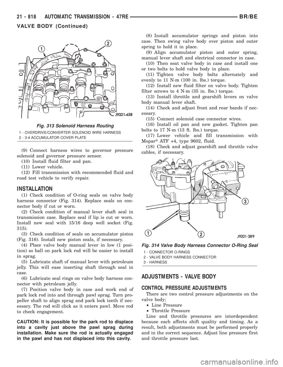
(1) Check condition of O-ring seals on valve body
harness connector (Fig. 314). Replace seals on con-
nector body if cut or worn.
(2) Check condition of manual lever shaft seal in
transmission case. Replace seal if lip is cut or worn.
Install new seal with 15/16 deep well socket (Fig.
315).
(3) Check condition of seals on accumulator piston
(Fig. 316). Install new piston seals, if necessary.
(4) Place valve body manual lever in low (1 posi-
tion) so ball on park lock rod will be easier to install
in sprag.
(5) Lubricate shaft of manual lever with petroleum
jelly. This will ease inserting shaft through seal in
case.
(6) Lubricate seal rings on valve body harness con-
nector with petroleum jelly.
(7) Position valve body in case and work end of
park lock rod into and through pawl sprag. Turn pro-
peller shaft to align sprag and park lock teeth if nec-
essary. The rod will click as it enters pawl. Move rod
to check engagement.
CAUTION: It is possible for the park rod to displace
into a cavity just above the pawl sprag during
installation. Make sure the rod is actually engaged
in the pawl and has not displaced into this cavity.(8) Install accumulator springs and piston into
case. Then swing valve body over piston and outer
spring to hold it in place.
(9) Align accumulator piston and outer spring,
manual lever shaft and electrical connector in case.
(10) Then seat valve body in case and install one
or two bolts to hold valve body in place.
(11) Tighten valve body bolts alternately and
evenly to 11 N´m (100 in. lbs.) torque.
(12) Install new fluid filter on valve body. Tighten
filter screws to 4 N´m (35 in. lbs.) torque.
(13) Install throttle and gearshift levers on valve
body manual lever shaft.
(14) Check and adjust front and rear bands if nec-
essary.
(15) Connect solenoid case connector wires.
(16) Install oil pan and new gasket. Tighten pan
bolts to 17 N´m (13 ft. lbs.) torque.
(17) Lower vehicle and fill transmission with
MopartATF +4, type 9602, fluid.
(18) Check and adjust gearshift and throttle valve
cables, if necessary.
ADJUSTMENTS - VALVE BODY
CONTROL PRESSURE ADJUSTMENTS
There are two control pressure adjustments on the
valve body;
²Line Pressure
²Throttle Pressure
Line and throttle pressures are interdependent
because each affects shift quality and timing. As a
result, both adjustments must be performed properly
and in the correct sequence. Adjust line pressure first
and throttle pressure last.
Fig. 313 Solenoid Harness Routing
1 - OVERDRIVE/CONVERTER SOLENOID WIRE HARNESS
2 - 3-4 ACCUMULATOR COVER PLATE
Fig. 314 Valve Body Harness Connector O-Ring Seal
1 - CONNECTOR O-RINGS
2 - VALVE BODY HARNESS CONNECTOR
3 - HARNESS
21 - 818 AUTOMATIC TRANSMISSION - 47REBR/BE
VALVE BODY (Continued)
Page 2652 of 2889
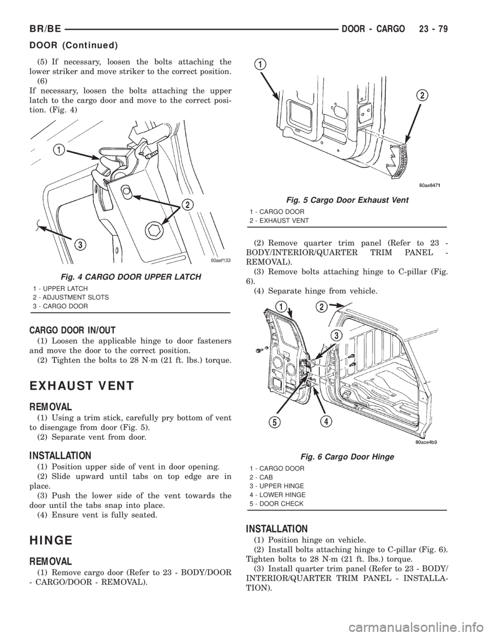
(5) If necessary, loosen the bolts attaching the
lower striker and move striker to the correct position.
(6)
If necessary, loosen the bolts attaching the upper
latch to the cargo door and move to the correct posi-
tion. (Fig. 4)
CARGO DOOR IN/OUT
(1) Loosen the applicable hinge to door fasteners
and move the door to the correct position.
(2) Tighten the bolts to 28 N´m (21 ft. lbs.) torque.
EXHAUST VENT
REMOVAL
(1) Using a trim stick, carefully pry bottom of vent
to disengage from door (Fig. 5).
(2) Separate vent from door.
INSTALLATION
(1) Position upper side of vent in door opening.
(2) Slide upward until tabs on top edge are in
place.
(3) Push the lower side of the vent towards the
door until the tabs snap into place.
(4) Ensure vent is fully seated.
HINGE
REMOVAL
(1) Remove cargo door (Refer to 23 - BODY/DOOR
- CARGO/DOOR - REMOVAL).(2) Remove quarter trim panel (Refer to 23 -
BODY/INTERIOR/QUARTER TRIM PANEL -
REMOVAL).
(3) Remove bolts attaching hinge to C-pillar (Fig.
6).
(4) Separate hinge from vehicle.
INSTALLATION
(1) Position hinge on vehicle.
(2) Install bolts attaching hinge to C-pillar (Fig. 6).
Tighten bolts to 28 N´m (21 ft. lbs.) torque.
(3) Install quarter trim panel (Refer to 23 - BODY/
INTERIOR/QUARTER TRIM PANEL - INSTALLA-
TION).
Fig. 4 CARGO DOOR UPPER LATCH
1 - UPPER LATCH
2 - ADJUSTMENT SLOTS
3 - CARGO DOOR
Fig. 5 Cargo Door Exhaust Vent
1 - CARGO DOOR
2 - EXHAUST VENT
Fig. 6 Cargo Door Hinge
1 - CARGO DOOR
2 - CAB
3 - UPPER HINGE
4 - LOWER HINGE
5 - DOOR CHECK
BR/BEDOOR - CARGO 23 - 79
DOOR (Continued)
Page 2706 of 2889
LUMBAR SUPPORT
REMOVAL
(1) Remove the seat back cover. (Refer to 23 -
BODY/SEATS/SEAT BACK COVER - REMOVAL).
(2) Disengage the heated seat connectors.
(3) Partially separate the seat back foam to access
the lumbar frame clips.
(4) Separate the lumbar assembly from the seat
frame.
INSTALLATION
(1) Position the lumbar assembly on the seat back
frame.
(2) Engage the retaining clips on the seat frame.
(3) Route the lumbar wire harness through seat
assembly.
(4) Engage the heated seat wire connectors.
(5) Install the seat back cover. (Refer to 23 -
BODY/SEATS/SEAT BACK COVER - INSTALLA-
TION).
(6) Perform a function check on the seat opera-
tions.
SEAT - BENCH SEAT
REMOVAL
(1) Move seat track to forward position.
(2) Hinge seat backs forward.
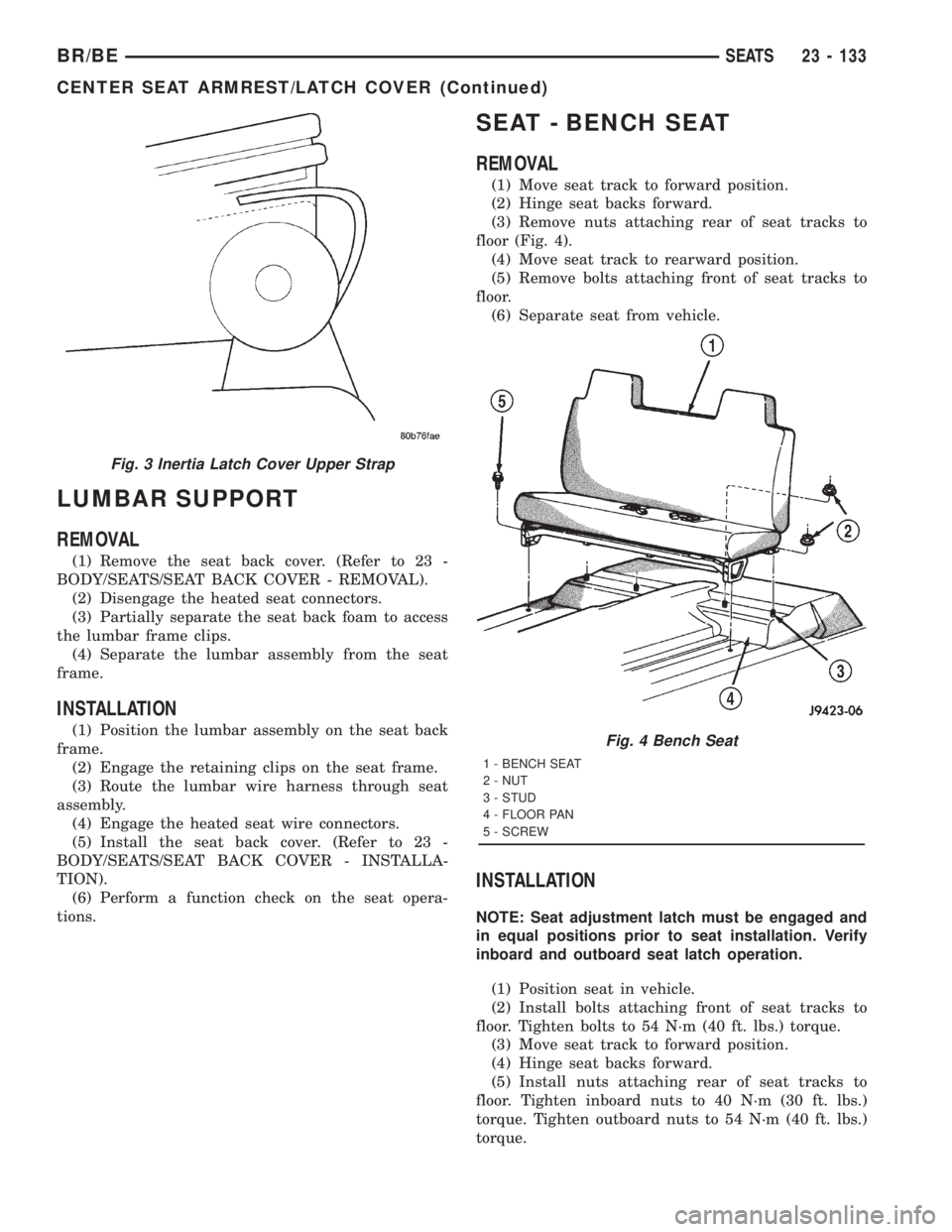
(3) Remove nuts attaching rear of seat tracks to
floor (Fig. 4).
(4) Move seat track to rearward position.
(5) Remove bolts attaching front of seat tracks to
floor.
(6) Separate seat from vehicle.
INSTALLATION
NOTE: Seat adjustment latch must be engaged and
in equal positions prior to seat installation. Verify
inboard and outboard seat latch operation.
(1) Position seat in vehicle.
(2) Install bolts attaching front of seat tracks to
floor. Tighten bolts to 54 N´m (40 ft. lbs.) torque.
(3) Move seat track to forward position.
(4) Hinge seat backs forward.
(5) Install nuts attaching rear of seat tracks to
floor. Tighten inboard nuts to 40 N´m (30 ft. lbs.)
torque. Tighten outboard nuts to 54 N´m (40 ft. lbs.)
torque.
Fig. 3 Inertia Latch Cover Upper Strap
Fig. 4 Bench Seat
1 - BENCH SEAT
2 - NUT
3 - STUD
4 - FLOOR PAN
5 - SCREW
BR/BESEATS 23 - 133
CENTER SEAT ARMREST/LATCH COVER (Continued)
Page 2838 of 2889
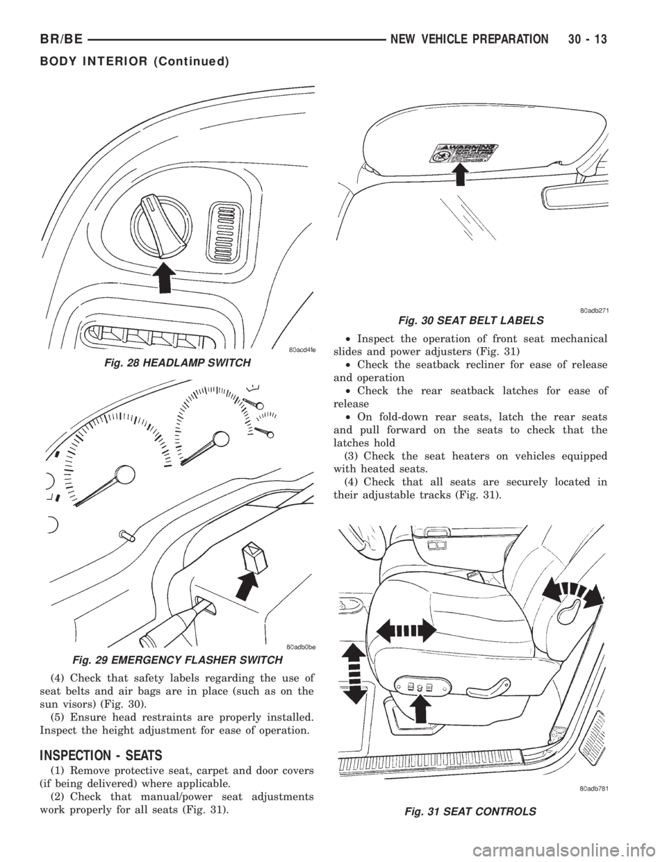
(4) Check that safety labels regarding the use of
seat belts and air bags are in place (such as on the
sun visors) (Fig. 30).
(5) Ensure head restraints are properly installed.
Inspect the height adjustment for ease of operation.
INSPECTION - SEATS
(1) Remove protective seat, carpet and door covers
(if being delivered) where applicable.
(2) Check that manual/power seat adjustments
work properly for all seats (Fig. 31).²Inspect the operation of front seat mechanical
slides and power adjusters (Fig. 31)
²Check the seatback recliner for ease of release
and operation
²Check the rear seatback latches for ease of
release
²On fold-down rear seats, latch the rear seats
and pull forward on the seats to check that the
latches hold
(3) Check the seat heaters on vehicles equipped
with heated seats.
(4) Check that all seats are securely located in
their adjustable tracks (Fig. 31).
Fig. 31 SEAT CONTROLS
Fig. 28 HEADLAMP SWITCH
Fig. 29 EMERGENCY FLASHER SWITCH
Fig. 30 SEAT BELT LABELS
BR/BENEW VEHICLE PREPARATION 30 - 13
BODY INTERIOR (Continued)
Page 2840 of 2889
ROAD TEST
DESCRIPTION - ROAD TEST INSPECTION
The following items must be inspected during the
road test portion of the new vehicle inspection.
²Check neutral safety switch operation
²Check operation of shift/clutch interlock system
²Check operation of gauges and warning lights
²Check horn operation
²Check operation of turn signals and emergency
flashers
²Check all mirror adjustments, including day/
night function
²Check windshield wipers for proper wipe pattern
and intermittent mode (if equipped)
²Check washer spray pattern
²Check heater, defroster and air conditioning for
proper operation
²Check that the fan operates quietly
²Check the rear window defroster (if equipped)
²Leave air selection lever in the fresh air position
²Check the rear heater and air conditioning for
proper operation
²Check the rear air register locations
²Check that the indicator lamps operate properly
²Check the operation of the radio, cassette and/or
compact disc player, and that sound quality is good
²Ensure that the clock displays the correct time
²Check that the trip computer/maintenance
reminder operates in all modes
²Check all speed control functions
²Check the service brakes to ensure that they
stop the vehicle in a straight line, without noise,
shudder or vibration
²Check the brake warning light
²Check the parking brake operation
²Check the engine's performance
²Check the transmission's performance for
smooth, quiet operation. If the vehicle is a 4x4, check
that the transfer case shifts easily among all ranges
²Check Autostick function (if equipped)
²Check the vehicle's steering and handling
²The steering wheel should be centered when
traveling in a straight line
²The vehicle should not pull or vibrate
²Check for squeaks, rattles and wind noise
²Check any other vehicle aspects you believe are
important, but that may not be included on the New
Vehicle Preparation Form
²Fill fuel tank with specified grade of fuel
INSPECTION - FUEL
Fill fuel tank with specified grade of gasoline (reg-
ular, midgrade or premium).
INSPECTION - OTHER
As part of DaimlerChrysler's Customer One philos-
ophy, the ªOtherº blank is provided on the New Vehi-
cle Preparation Form. This is designed to encourage
you to check any aspects of vehicle operation that
you believe are important to your customers, but that
do not appear elsewhere on the form.
INSPECTION - SQUEAKS, RATTLES AND WIND
NOISE
(1) Make sure that the instrument panel, glove
box, seats, steering wheel and column are free from
squeaks and rattles. Tighten any obvious loose fas-
teners.
(2) Check that the windows and doors are free
from squeaks, rattles and wind noise.
(3) Check that the vehicle exterior is free from
squeaks, rattles and noise, front and rear.
(4) Make sure that all interior panels are free from
squeaks and rattles.
INSPECTION - STEERING AND HANDLING
(1) Check that the power assist works properly (if
equipped). Steering should not require excessive
effort.
(2) Make sure the steering wheel does not vibrate
at idle or road speed.
(3) Ensure that the steering wheel is centered
when traveling straight ahead.
(4) Check that the vehicle does not drift to one
side.
(5) Make sure that the vehicle does not vibrate/
shake.
INSPECTION - TRANSMISSION/TRANSFER
CASE
AUTOMATIC TRANSMISSION
(1) Make sure that the park lock holds the vehicle
With the vehicle on a grade, put automatic trans-
mission in PARK and slowly release the service
brake to see if park lock holds. If it does not hold, the
transmission requires further service.
(2) Make sure shift lever operates easily/ smoothly
(Fig. 36).
Check for smooth shifting. Check for proper
upshifting and downshifting.
MANUAL TRANSMISSION
(1) Check that the shifter operates easily (Fig. 38).
(2) Make sure that the clutch operates smoothly
(Fig. 37).
(3) Look for proper synchronization.
The gears should not grind.
BR/BENEW VEHICLE PREPARATION 30 - 15