seat adjustment DODGE RAM 2001 Service Owner's Guide
[x] Cancel search | Manufacturer: DODGE, Model Year: 2001, Model line: RAM, Model: DODGE RAM 2001Pages: 2889, PDF Size: 68.07 MB
Page 1421 of 2889
(10)Verify valve lash adjustment (Refer to 9 -
ENGINE/CYLINDER HEAD/INTAKE/EXHAUST
VALVES & SEATS - STANDARD PROCEDURE).
(11)
Install the cylinder head cover and reusable gas-
ket (Fig. 85) (Refer to 9 - ENGINE/CYLINDER HEAD/
CYLINDER HEAD COVER(S) - INSTALLATION).
(12) Install gear housing cover (Refer to 9 -
ENGINE/VALVE TIMING/GEAR HOUSING COVER
- INSTALLATION).
(13) Install the crankshaft damper (Fig. 83) (Refer
to 9 - ENGINE/ENGINE BLOCK/VIBRATION
DAMPER - INSTALLATION).
(14) Install the fan support/hub assembly (Fig. 82)
and tighten bolts to 24 N´m (18 ft. lbs.) torque.
(15) Install the crankcase breather housing (Refer
to 9 - ENGINE - INSTALLATION).
(16) Install the charge air cooler (with a/c con-
denser and auxiliary transmission oil cooler, if
equipped) and tighten the mounting bolts to 2 N´m
(17 in. lbs.) torque.
(17) Connect charge air cooler inlet and outlet
pipes. Tighten clamps to 10 N´m (100 in. lbs.) torque.
(18) Install the radiator upper support panel.
(19) Close radiator petcock and lower the radiator
into the engine compartment. Tighten the mounting
bolts to 11 N´m (95 in. lbs.) torque.
(20) Raise vehicle on hoist.
(21)
Connect radiator lower hose and install clamp.
(22) Connect transmission auxiliary oil cooler lines
(if equipped).
(23) Lower vehicle.
(24) Install the fan shroud and tighten the mount-
ing screws to 6 N´m (50 in. lbs.) torque.(25) Install the viscous fan/drive assembly (Refer
to 7 - COOLING/ENGINE/RADIATOR FAN -
INSTALLATION).
(26) Install the coolant recovery and windshield
washer fluid reservoirs to the fan shroud.
(27) Connect the coolant recovery hose to the radi-
ator filler neck.
(28) Install the accessory drive belt (Refer to 7 -
COOLING/ACCESSORY DRIVE/DRIVE BELTS -
INSTALLATION).
(29) Install the front bumper assembly (Refer to 13
- FRAMES & BUMPERS/BUMPERS/FRONT
BUMPER - INSTALLATION).
(30) Add engine coolant (Refer to 7 - COOLING -
STANDARD PROCEDURE).
(31) Charge A/C system with refrigerant (if A/C
equipped) (Refer to 24 - HEATING & AIR CONDI-
TIONING/PLUMBING - STANDARD PROCEDURE).
(32) Connect the battery negative cables.
(33) Start engine and check for engine oil and cool-
ant leaks.
CONNECTING ROD BEARINGS
STANDARD PROCEDUREÐCONNECTING ROD
BEARING AND CRANKSHAFT JOURNAL
CLEARANCE
Measure the connecting rod bore with the bearings
installed and the bolts tightened to 100 N´m (73 ft.
lbs.) torque.
Record the smaller diameter.
Measure the diameter of the rod journal at the
location shown (Fig. 99). Calculate the average diam-
eter for each side of the journal.
The clearance is the difference between the con-
necting rod bore (smallest diameter) and the average
diameter for each side of the crankshaft journal.
CONNECTING ROD JOURNAL DIAMETER
LIMITS CHART
DESCRIPTION MEASUREMENT
CRANKSHAFT ROD
JOURNAL DIAMETERMINIMUM 68.962 mm
(2.715 in.)
MAXIMUM 69.013 mm
(2.717 in.)
OUT-OF-ROUND MAXIMUM 0.050 mm
(0.002 in.)
TAPER MAXIMUM 0.013 mm
(0.0005 in.)
BEARING CLEARANCE MAXIMUM 0.089 mm
(0.0035 in.)
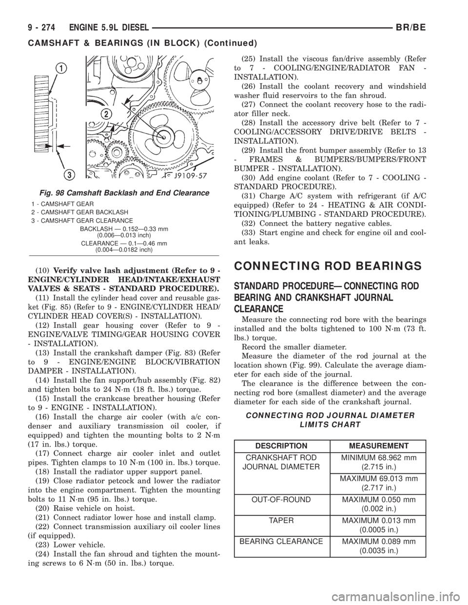
Fig. 98 Camshaft Backlash and End Clearance
1 - CAMSHAFT GEAR
2 - CAMSHAFT GEAR BACKLASH
3 - CAMSHAFT GEAR CLEARANCE
BACKLASH Ð 0.152Ð0.33 mm
(0.006Ð0.013 inch)
CLEARANCE Ð 0.1Ð0.46 mm
(0.004Ð0.0182 inch)
9 - 274 ENGINE 5.9L DIESELBR/BE
CAMSHAFT & BEARINGS (IN BLOCK) (Continued)
Page 1602 of 2889
NOTE: A new grommet should be used when ever
the rod is disconnected from the lever.
(3) Remove the shipping lock pin if necessary.
(4) Install the column through the floor pan.
(5) Position the column bracket breakaway cap-
sules on the mounting studs. Install, butloose
assemblethe two upper bracket nuts.
(6) With the front wheels in the straight-ahead
position. Align steering column shaft to the coupler.
Install anewpinch bolt and tighten to 49 N´m (36
ft. lbs.).
(7) Clip the wiring harness on the steering column.
Connect the multi- function switch wiring and
tighten with 7mm socket.
(8) Install the upper fixed shroud.
(9) Be sure both breakaway capsules are fully
seated in the slots in the column support bracket.
Pull the column rearward then tighten upper bracket
nuts to 12 N´m (105 in. lbs.).
(10) Tighten the toe plate to floor pan attaching
nuts to 22.5 N´m (200 in. lbs.).
(11) Install the wiring connections to the column.
Install the lower fixed shroud.(12) Column shift vehicles, install the PRNDL
driver cable. Place shifter in Park position. If indica-
tor needs adjusting, turn thumb screw on cable
retainer to adjust cable.
(13) Install the lock housing shrouds. Install the
tilt lever (if equipped).
(14) Install the knee blocker and steering column
opening cover, (Refer to 23 - BODY/INSTRUMENT
PANEL/STEERING COLUMN OPENING COVER -
INSTALLATION).
(15) Install steering wheel and tighten nut to 61
N´m (45 ft. lbs.), (Refer to 19 - STEERING/COL-
UMN/STEERING WHEEL - INSTALLATION).
(16) Install the airbag, (Refer to 8 - ELECTRICAL/
RESTRAINTS/DRIVER AIRBAG - INSTALLATION).
(17) Column shift vehicles, connect the shift link
rod to the transmission shift lever. Use multi-purpose
lubricant, or an equivalent product, to aid the instal-
lation.
(18) Install the battery ground (negative) cable.
(19) Verify operation of the automatic transmission
shift linkage and adjust as necessary, (Refer to 21 -
TRANSMISSION/TRANSAXLE/AUTOMATIC -
44RE/GEAR SHIFT CABLE - ADJUSTMENTS).
SPECIFICATIONS
TORQUE CHART
TORQUE SPECIFICATIONS
DESCRIPTION N´m Ft. Lbs. In. Lbs.
Steering Wheel
Nut61 45 Ð
Steering Coupler
Bolt49 36 Ð
Steering Column
Upper Bracket12 Ð 105
Steering Column
Toe Plate23 Ð 200
KEY-IN IGNITION SWITCH
DESCRIPTION
The key-in ignition switch is integral to the igni-
tion switch, which is mounted on the right side of the
steering column. It closes a path to ground for the
Central Timer Module (CTM) when the ignition key
is inserted in the ignition lock cylinder and thedriver door ajar switch is closed (driver door is open).
The key-in ignition switch opens the ground path
when the key is removed from the ignition lock cyl-
inder. The ground path is also opened when the
driver door ajar switch is open (driver door is closed).
The key-in ignition switch cannot be repaired and,
if faulty or damaged, the entire ignition switch must
be replaced,(Refer to 19 - STEERING/COLUMN/IG-
NITION SWITCH - REMOVAL).
BR/BECOLUMN 19 - 9
COLUMN (Continued)
Page 1616 of 2889
INSTALLATION
(1) Install pitman shaft bearing into housing with
a bearing driver and handle.
(2) Coat the oil seal and washer withspecial
greasesupplied with the new seal.
(3) Install the oil seal with a driver and handle.
(4) Install backup washer.
(5) Install the retainer ring with snap ring pliers.
(6) Coat the dust seal withspecial greasesup-
plied with the new seal.
(7) Install dust seal with a driver and handle.
(8) Install pitman shaft to side cover by screwing
shaft in until it fully seats to side cover.
(9) Install preload adjuster nut.Do not tighten
nut until after Over-Center Rotation Torque
adjustment has been made.
(10) Install gasket to side cover and bend tabs
around edges of side cover (Fig. 11).
(11) Install pitman shaft assembly and side cover
to housing.
(12) Install side cover bolts and tighten to 60 N´m
(44 ft. lbs.).
(13) Perform over-center rotation torque adjust-
ment, (Refer to 19 - STEERING/GEAR - ADJUST-
MENTS).
PITMAN SHAFT SEAL
REMOVAL
(1) Clean exposed end of pitman shaft and housing
with a wire brush.
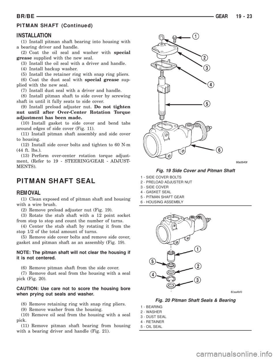
(2) Remove preload adjuster nut (Fig. 19).
(3) Rotate the stub shaft with a 12 point socket
from stop to stop and count the number of turns.
(4) Center the stub shaft by rotating it from the
stop 1/2 of the total amount of turns.
(5) Remove side cover bolts and remove side cover,
gasket and pitman shaft as an assembly (Fig. 19).
NOTE: The pitman shaft will not clear the housing if
it is not centered.
(6) Remove pitman shaft from the side cover.
(7) Remove dust seal from the housing with a seal
pick (Fig. 20).
CAUTION: Use care not to score the housing bore
when prying out seals and washer.
(8) Remove retaining ring with snap ring pliers.
(9) Remove washer from the housing.
(10) Remove oil seal from the housing with a seal
pick.
(11) Remove pitman shaft bearing from housing
with a bearing driver and handle (Fig. 21).
Fig. 19 Side Cover and Pitman Shaft
1 - SIDE COVER BOLTS
2 - PRELOAD ADJUSTER NUT
3 - SIDE COVER
4 - GASKET SEAL
5 - PITMAN SHAFT GEAR
6 - HOUSING ASSEMBLY
Fig. 20 Pitman Shaft Seals & Bearing
1 - BEARING
2 - WASHER
3 - DUST SEAL
4 - RETAINER
5 - OIL SEAL
BR/BEGEAR 19 - 23
PITMAN SHAFT (Continued)
Page 1619 of 2889
(8) Remove the O-ring between the worm shaft
and the stub shaft.
INSTALLATION
NOTE: Clean and dry all components, then lubricate
with power steering fluid.(1) Install spool valve spool O-ring.
(2) Install spool valve in valve body by pushing
and rotating. Hole in spool valve for stub shaft pin
must be accessible from opposite end of valve body.
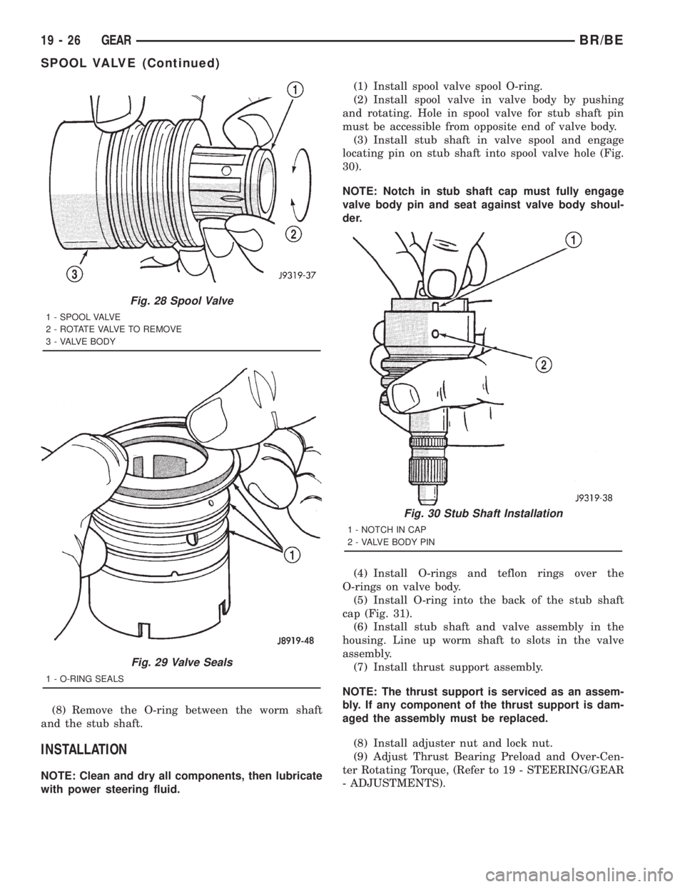
(3) Install stub shaft in valve spool and engage
locating pin on stub shaft into spool valve hole (Fig.
30).
NOTE: Notch in stub shaft cap must fully engage
valve body pin and seat against valve body shoul-
der.
(4) Install O-rings and teflon rings over the
O-rings on valve body.
(5) Install O-ring into the back of the stub shaft
cap (Fig. 31).
(6) Install stub shaft and valve assembly in the
housing. Line up worm shaft to slots in the valve
assembly.
(7) Install thrust support assembly.
NOTE: The thrust support is serviced as an assem-
bly. If any component of the thrust support is dam-
aged the assembly must be replaced.
(8) Install adjuster nut and lock nut.
(9) Adjust Thrust Bearing Preload and Over-Cen-
ter Rotating Torque, (Refer to 19 - STEERING/GEAR
- ADJUSTMENTS).
Fig. 28 Spool Valve
1 - SPOOL VALVE
2 - ROTATE VALVE TO REMOVE
3 - VALVE BODY
Fig. 29 Valve Seals
1 - O-RING SEALS
Fig. 30 Stub Shaft Installation
1 - NOTCH IN CAP
2 - VALVE BODY PIN
19 - 26 GEARBR/BE
SPOOL VALVE (Continued)
Page 1623 of 2889
(11) Install the rack piston and arbor tool into the
housing.
(12) Hold arbor tightly against worm shaft and
turn stub shaft CLOCKWISE until rack piston is
seated on worm shaft.
(13) Install pitman shaft and side cover in the
housing.
(14) Install rack piston plug and tighten to 150
N´m (111 ft. lbs.).
(15) Install housing end plug, (Refer to 19 -
STEERING/GEAR/STEERING GEAR HOUSING
PLUG - INSTALLATION).
(16) Adjust worm shaft thrust bearing preload and
over-center rotating torque, (Refer to 19 - STEER-
ING/GEAR - ADJUSTMENTS).
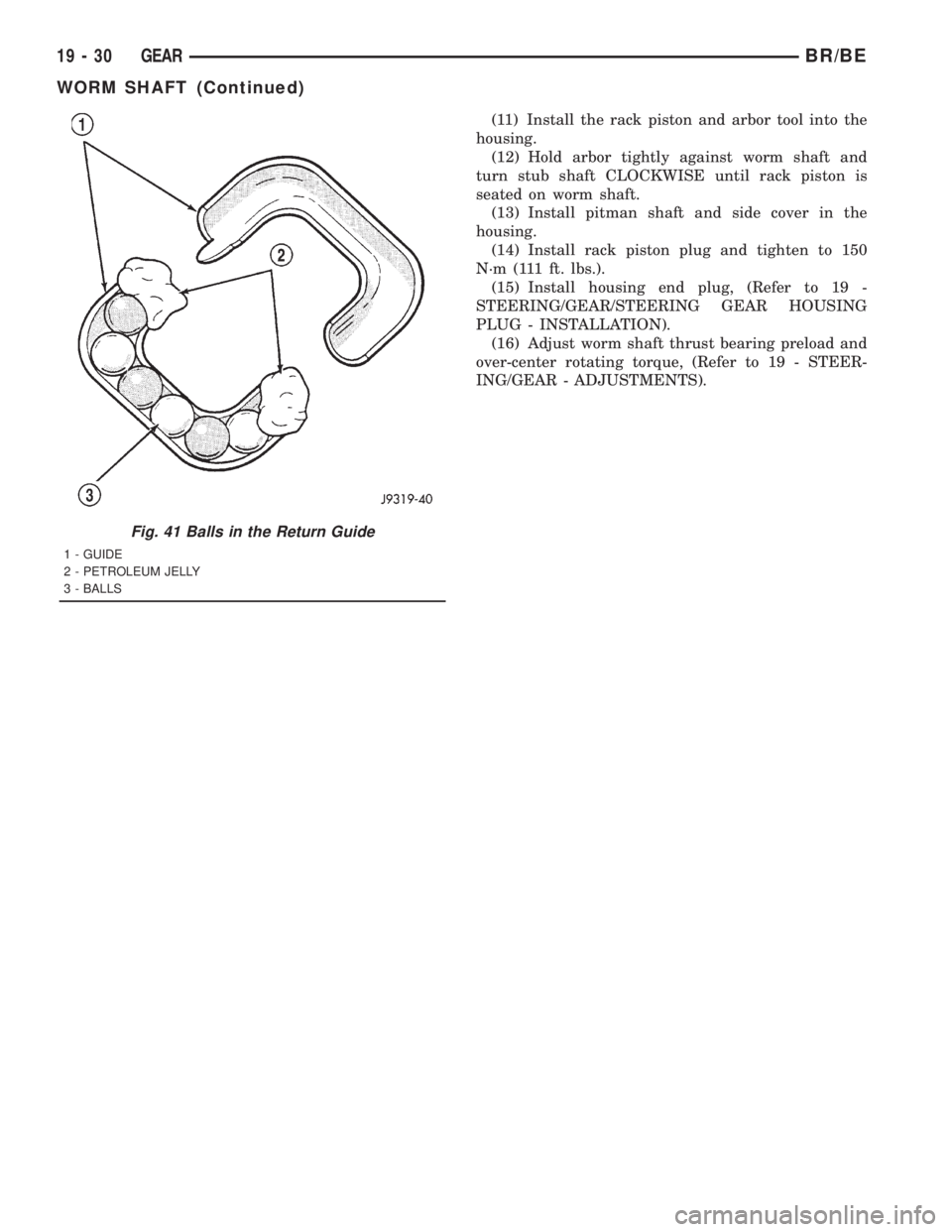
Fig. 41 Balls in the Return Guide
1 - GUIDE
2 - PETROLEUM JELLY
3 - BALLS
19 - 30 GEARBR/BE
WORM SHAFT (Continued)
Page 1713 of 2889
MAINSHAFT END PLAY
(1) Install mainshaft rear bearing cup in case and
over bearing. Tap bearing cup into place with plastic
mallet.
(2) Install rear bearing plate to hold mainshaft
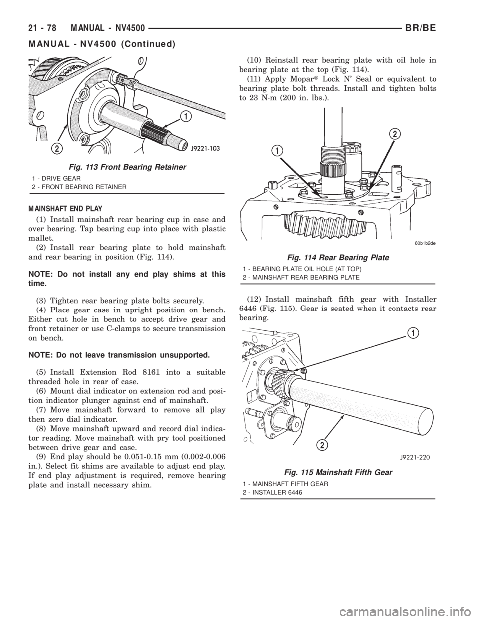
and rear bearing in position (Fig. 114).
NOTE: Do not install any end play shims at this
time.
(3) Tighten rear bearing plate bolts securely.
(4) Place gear case in upright position on bench.
Either cut hole in bench to accept drive gear and
front retainer or use C-clamps to secure transmission
on bench.
NOTE: Do not leave transmission unsupported.
(5) Install Extension Rod 8161 into a suitable
threaded hole in rear of case.
(6) Mount dial indicator on extension rod and posi-
tion indicator plunger against end of mainshaft.
(7) Move mainshaft forward to remove all play
then zero dial indicator.
(8) Move mainshaft upward and record dial indica-
tor reading. Move mainshaft with pry tool positioned
between drive gear and case.
(9) End play should be 0.051-0.15 mm (0.002-0.006
in.). Select fit shims are available to adjust end play.
If end play adjustment is required, remove bearing
plate and install necessary shim.(10) Reinstall rear bearing plate with oil hole in
bearing plate at the top (Fig. 114).
(11) Apply MopartLock N' Seal or equivalent to
bearing plate bolt threads. Install and tighten bolts
to 23 N´m (200 in. lbs.).
(12) Install mainshaft fifth gear with Installer
6446 (Fig. 115). Gear is seated when it contacts rear
bearing.
Fig. 113 Front Bearing Retainer
1 - DRIVE GEAR
2 - FRONT BEARING RETAINER
Fig. 114 Rear Bearing Plate
1 - BEARING PLATE OIL HOLE (AT TOP)
2 - MAINSHAFT REAR BEARING PLATE
Fig. 115 Mainshaft Fifth Gear
1 - MAINSHAFT FIFTH GEAR
2 - INSTALLER 6446
21 - 78 MANUAL - NV4500BR/BE
MANUAL - NV4500 (Continued)
Page 1880 of 2889
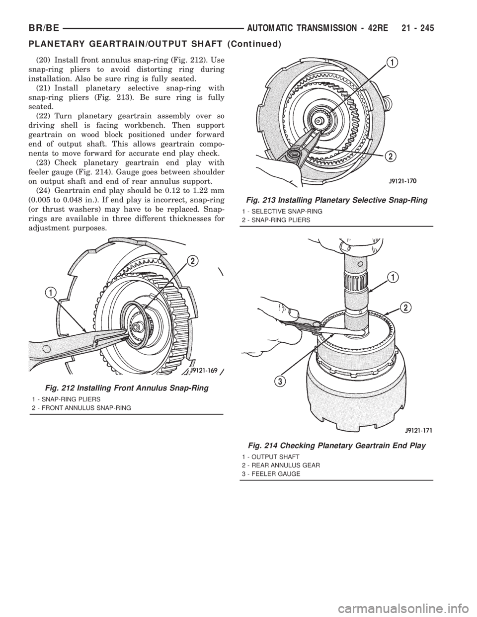
(20) Install front annulus snap-ring (Fig. 212). Use
snap-ring pliers to avoid distorting ring during
installation. Also be sure ring is fully seated.
(21) Install planetary selective snap-ring with
snap-ring pliers (Fig. 213). Be sure ring is fully
seated.
(22) Turn planetary geartrain assembly over so
driving shell is facing workbench. Then support
geartrain on wood block positioned under forward
end of output shaft. This allows geartrain compo-
nents to move forward for accurate end play check.
(23) Check planetary geartrain end play with
feeler gauge (Fig. 214). Gauge goes between shoulder
on output shaft and end of rear annulus support.
(24) Geartrain end play should be 0.12 to 1.22 mm
(0.005 to 0.048 in.). If end play is incorrect, snap-ring
(or thrust washers) may have to be replaced. Snap-
rings are available in three different thicknesses for
adjustment purposes.
Fig. 212 Installing Front Annulus Snap-Ring
1 - SNAP-RING PLIERS
2 - FRONT ANNULUS SNAP-RING
Fig. 213 Installing Planetary Selective Snap-Ring
1 - SELECTIVE SNAP-RING
2 - SNAP-RING PLIERS
Fig. 214 Checking Planetary Geartrain End Play
1 - OUTPUT SHAFT
2 - REAR ANNULUS GEAR
3 - FEELER GAUGE
BR/BEAUTOMATIC TRANSMISSION - 42RE 21 - 245
PLANETARY GEARTRAIN/OUTPUT SHAFT (Continued)
Page 1936 of 2889
3-4 ACCUMULATOR
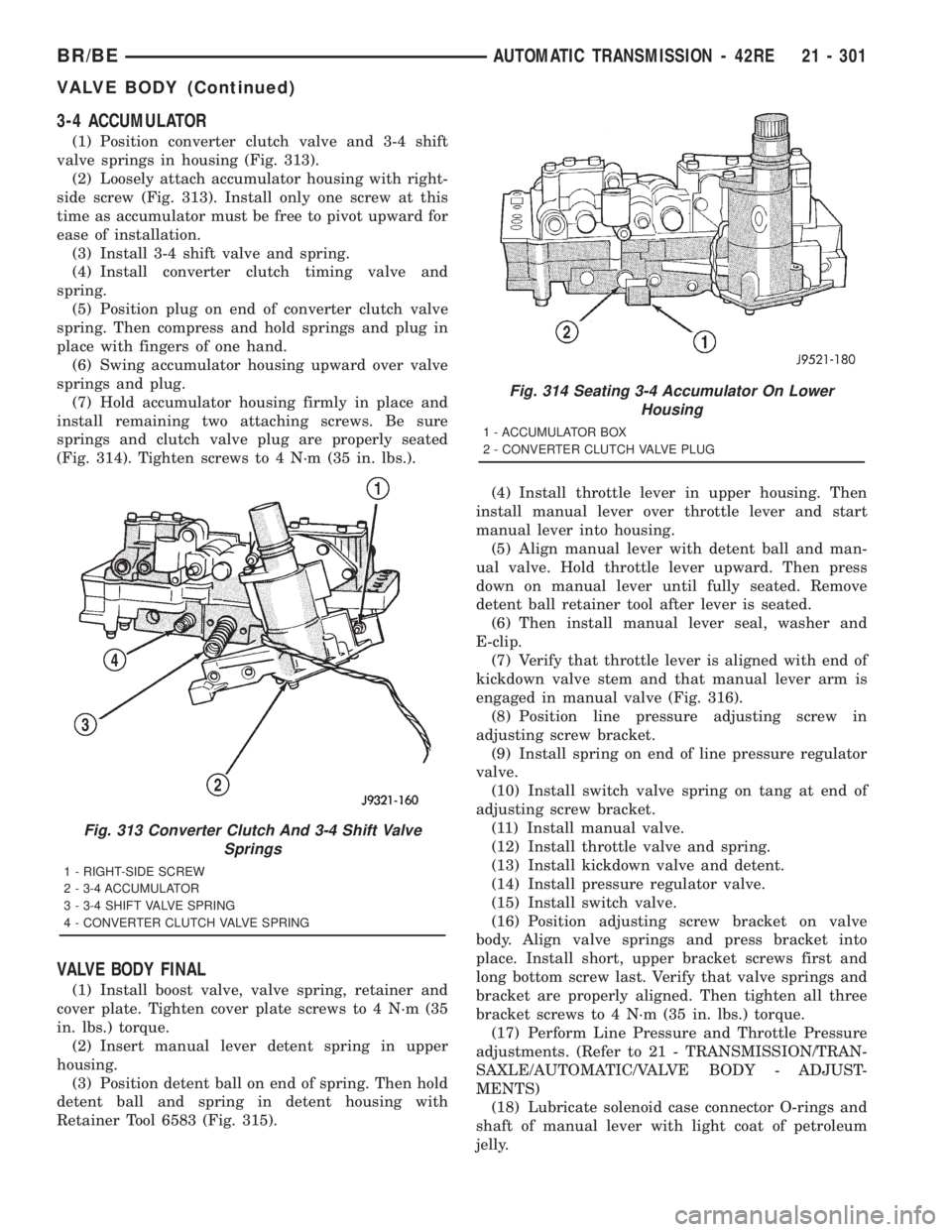
(1) Position converter clutch valve and 3-4 shift
valve springs in housing (Fig. 313).
(2) Loosely attach accumulator housing with right-
side screw (Fig. 313). Install only one screw at this
time as accumulator must be free to pivot upward for
ease of installation.
(3) Install 3-4 shift valve and spring.
(4) Install converter clutch timing valve and
spring.
(5) Position plug on end of converter clutch valve
spring. Then compress and hold springs and plug in
place with fingers of one hand.
(6) Swing accumulator housing upward over valve
springs and plug.
(7) Hold accumulator housing firmly in place and
install remaining two attaching screws. Be sure
springs and clutch valve plug are properly seated
(Fig. 314). Tighten screws to 4 N´m (35 in. lbs.).
VALVE BODY FINAL
(1) Install boost valve, valve spring, retainer and
cover plate. Tighten cover plate screws to 4 N´m (35
in. lbs.) torque.
(2) Insert manual lever detent spring in upper
housing.
(3) Position detent ball on end of spring. Then hold
detent ball and spring in detent housing with
Retainer Tool 6583 (Fig. 315).(4) Install throttle lever in upper housing. Then
install manual lever over throttle lever and start
manual lever into housing.
(5) Align manual lever with detent ball and man-
ual valve. Hold throttle lever upward. Then press
down on manual lever until fully seated. Remove
detent ball retainer tool after lever is seated.
(6) Then install manual lever seal, washer and
E-clip.
(7) Verify that throttle lever is aligned with end of
kickdown valve stem and that manual lever arm is
engaged in manual valve (Fig. 316).
(8) Position line pressure adjusting screw in
adjusting screw bracket.
(9) Install spring on end of line pressure regulator
valve.
(10) Install switch valve spring on tang at end of
adjusting screw bracket.
(11) Install manual valve.
(12) Install throttle valve and spring.
(13) Install kickdown valve and detent.
(14) Install pressure regulator valve.
(15) Install switch valve.
(16) Position adjusting screw bracket on valve
body. Align valve springs and press bracket into
place. Install short, upper bracket screws first and
long bottom screw last. Verify that valve springs and
bracket are properly aligned. Then tighten all three
bracket screws to 4 N´m (35 in. lbs.) torque.
(17) Perform Line Pressure and Throttle Pressure
adjustments. (Refer to 21 - TRANSMISSION/TRAN-
SAXLE/AUTOMATIC/VALVE BODY - ADJUST-
MENTS)
(18) Lubricate solenoid case connector O-rings and
shaft of manual lever with light coat of petroleum
jelly.
Fig. 313 Converter Clutch And 3-4 Shift Valve
Springs
1 - RIGHT-SIDE SCREW
2 - 3-4 ACCUMULATOR
3 - 3-4 SHIFT VALVE SPRING
4 - CONVERTER CLUTCH VALVE SPRING
Fig. 314 Seating 3-4 Accumulator On Lower
Housing
1 - ACCUMULATOR BOX
2 - CONVERTER CLUTCH VALVE PLUG
BR/BEAUTOMATIC TRANSMISSION - 42RE 21 - 301
VALVE BODY (Continued)
Page 2050 of 2889
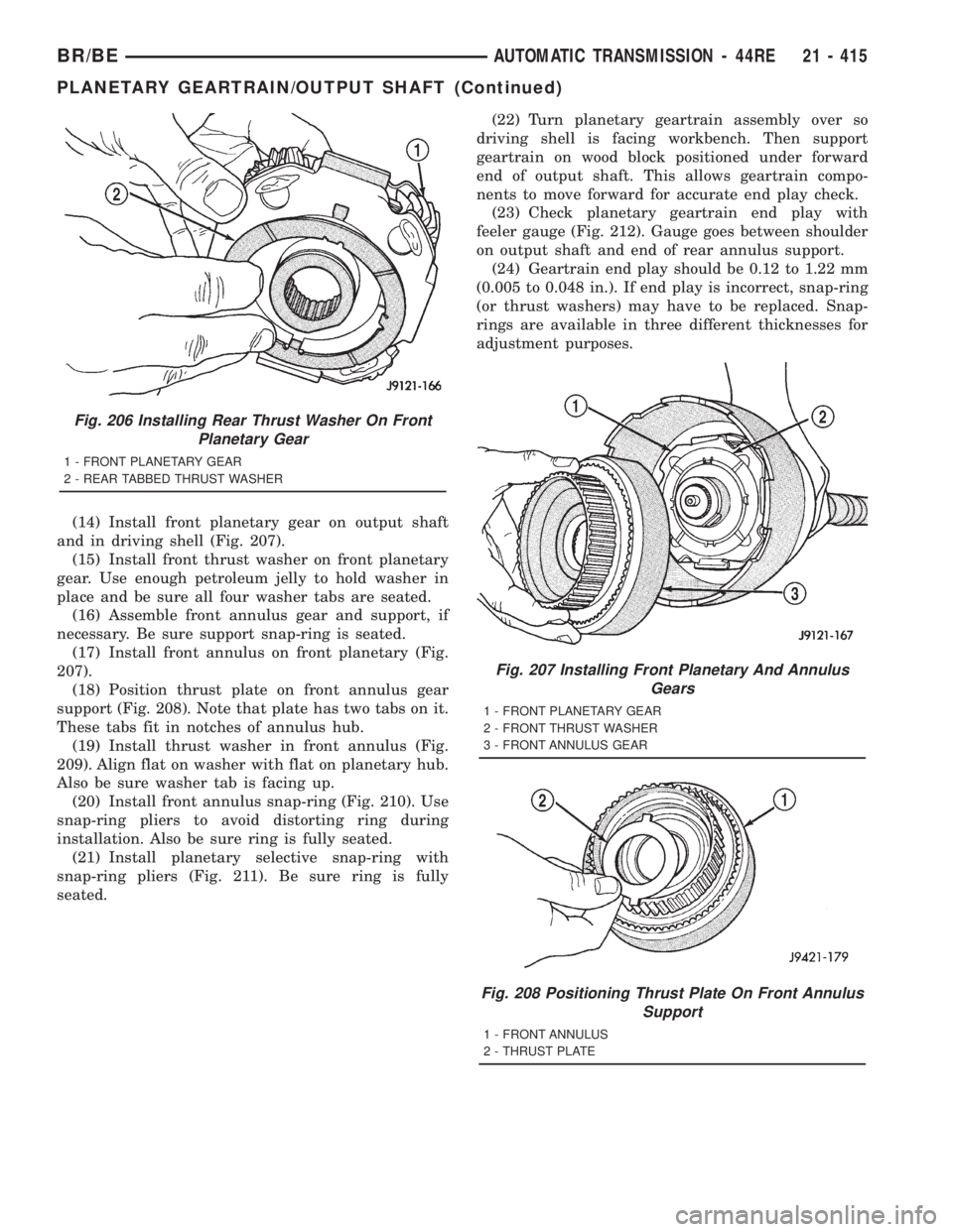
(14) Install front planetary gear on output shaft
and in driving shell (Fig. 207).
(15) Install front thrust washer on front planetary
gear. Use enough petroleum jelly to hold washer in
place and be sure all four washer tabs are seated.
(16) Assemble front annulus gear and support, if
necessary. Be sure support snap-ring is seated.
(17) Install front annulus on front planetary (Fig.
207).
(18) Position thrust plate on front annulus gear
support (Fig. 208). Note that plate has two tabs on it.
These tabs fit in notches of annulus hub.
(19) Install thrust washer in front annulus (Fig.
209). Align flat on washer with flat on planetary hub.
Also be sure washer tab is facing up.
(20) Install front annulus snap-ring (Fig. 210). Use
snap-ring pliers to avoid distorting ring during
installation. Also be sure ring is fully seated.
(21) Install planetary selective snap-ring with
snap-ring pliers (Fig. 211). Be sure ring is fully
seated.(22) Turn planetary geartrain assembly over so
driving shell is facing workbench. Then support
geartrain on wood block positioned under forward
end of output shaft. This allows geartrain compo-
nents to move forward for accurate end play check.
(23) Check planetary geartrain end play with
feeler gauge (Fig. 212). Gauge goes between shoulder
on output shaft and end of rear annulus support.
(24) Geartrain end play should be 0.12 to 1.22 mm
(0.005 to 0.048 in.). If end play is incorrect, snap-ring
(or thrust washers) may have to be replaced. Snap-
rings are available in three different thicknesses for
adjustment purposes.
Fig. 206 Installing Rear Thrust Washer On Front
Planetary Gear
1 - FRONT PLANETARY GEAR
2 - REAR TABBED THRUST WASHER
Fig. 207 Installing Front Planetary And Annulus
Gears
1 - FRONT PLANETARY GEAR
2 - FRONT THRUST WASHER
3 - FRONT ANNULUS GEAR
Fig. 208 Positioning Thrust Plate On Front Annulus
Support
1 - FRONT ANNULUS
2 - THRUST PLATE
BR/BEAUTOMATIC TRANSMISSION - 44RE 21 - 415
PLANETARY GEARTRAIN/OUTPUT SHAFT (Continued)
Page 2108 of 2889
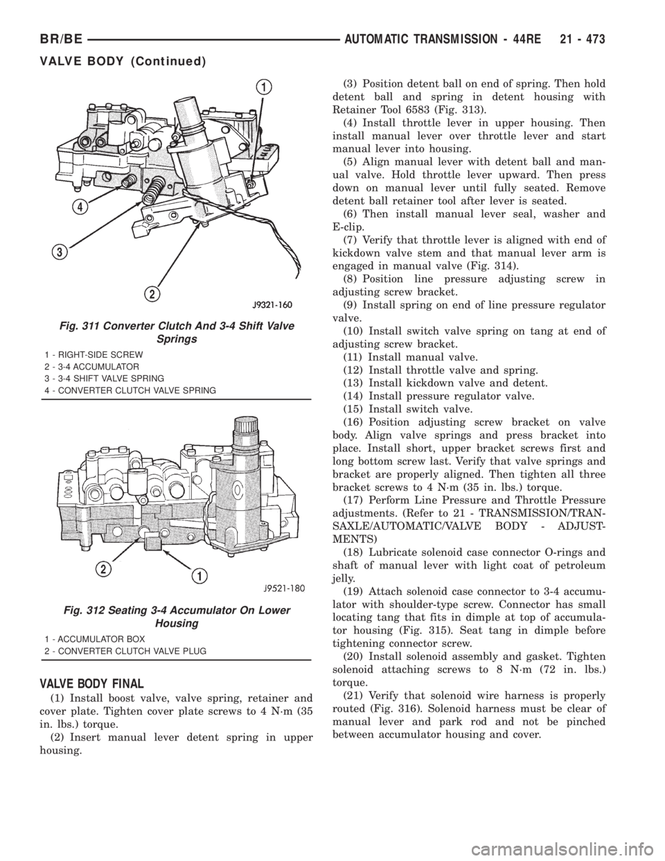
VALVE BODY FINAL
(1) Install boost valve, valve spring, retainer and
cover plate. Tighten cover plate screws to 4 N´m (35
in. lbs.) torque.
(2) Insert manual lever detent spring in upper
housing.(3) Position detent ball on end of spring. Then hold
detent ball and spring in detent housing with
Retainer Tool 6583 (Fig. 313).
(4) Install throttle lever in upper housing. Then
install manual lever over throttle lever and start
manual lever into housing.
(5) Align manual lever with detent ball and man-
ual valve. Hold throttle lever upward. Then press
down on manual lever until fully seated. Remove
detent ball retainer tool after lever is seated.
(6) Then install manual lever seal, washer and
E-clip.
(7) Verify that throttle lever is aligned with end of
kickdown valve stem and that manual lever arm is
engaged in manual valve (Fig. 314).
(8) Position line pressure adjusting screw in
adjusting screw bracket.
(9) Install spring on end of line pressure regulator
valve.
(10) Install switch valve spring on tang at end of
adjusting screw bracket.
(11) Install manual valve.
(12) Install throttle valve and spring.
(13) Install kickdown valve and detent.
(14) Install pressure regulator valve.
(15) Install switch valve.
(16) Position adjusting screw bracket on valve
body. Align valve springs and press bracket into
place. Install short, upper bracket screws first and
long bottom screw last. Verify that valve springs and
bracket are properly aligned. Then tighten all three
bracket screws to 4 N´m (35 in. lbs.) torque.
(17) Perform Line Pressure and Throttle Pressure
adjustments. (Refer to 21 - TRANSMISSION/TRAN-
SAXLE/AUTOMATIC/VALVE BODY - ADJUST-
MENTS)
(18) Lubricate solenoid case connector O-rings and
shaft of manual lever with light coat of petroleum
jelly.
(19) Attach solenoid case connector to 3-4 accumu-
lator with shoulder-type screw. Connector has small
locating tang that fits in dimple at top of accumula-
tor housing (Fig. 315). Seat tang in dimple before
tightening connector screw.
(20) Install solenoid assembly and gasket. Tighten
solenoid attaching screws to 8 N´m (72 in. lbs.)
torque.
(21) Verify that solenoid wire harness is properly
routed (Fig. 316). Solenoid harness must be clear of
manual lever and park rod and not be pinched
between accumulator housing and cover.
Fig. 311 Converter Clutch And 3-4 Shift Valve
Springs
1 - RIGHT-SIDE SCREW
2 - 3-4 ACCUMULATOR
3 - 3-4 SHIFT VALVE SPRING
4 - CONVERTER CLUTCH VALVE SPRING
Fig. 312 Seating 3-4 Accumulator On Lower
Housing
1 - ACCUMULATOR BOX
2 - CONVERTER CLUTCH VALVE PLUG
BR/BEAUTOMATIC TRANSMISSION - 44RE 21 - 473
VALVE BODY (Continued)