seat adjustment DODGE RAM 2001 Service Owner's Manual
[x] Cancel search | Manufacturer: DODGE, Model Year: 2001, Model line: RAM, Model: DODGE RAM 2001Pages: 2889, PDF Size: 68.07 MB
Page 1231 of 2889
(1) When refacing valve seats, it is important that
the correct size valve guide pilot be used for reseat-
ing stones. A true and complete surface must be
obtained.
(2) Measure the concentricity of valve seat using a
dial indicator. Total runout should not exceed 0.051
mm (0.002 in.) total indicator reading.
(3) Inspect the valve seat with Prussian blue, to
determine where the valve contacts the seat. To do
this, coat valve seat LIGHTLY with Prussian blue
then set valve in place. Rotate the valve with light
pressure. If the blue is transferred to the center of
valve face, contact is satisfactory. If the blue is trans-
ferred to the top edge of valve face, lower valve seat
with a 15É stone. If the blue is transferred to bottom
edge of valve face raise valve seat with a 60É stone.
(4) When seat is properly positioned the width of
intake seats should be 1.016-1.524 mm (0.040-0.060
in.). The width of the exhaust seats should be 1.524-
2.032 mm (0.060-0.080 in.).
VALVE SPRINGS
Whenever valves have been removed for inspection,
reconditioning or replacement, valve springs should
be tested. As an example the compression length of
the spring to be tested is 1-5/16 in.. Turn table of
Universal Valve Spring Tester Tool until surface is in
line with the 1-5/16 in. mark on the threaded stud.
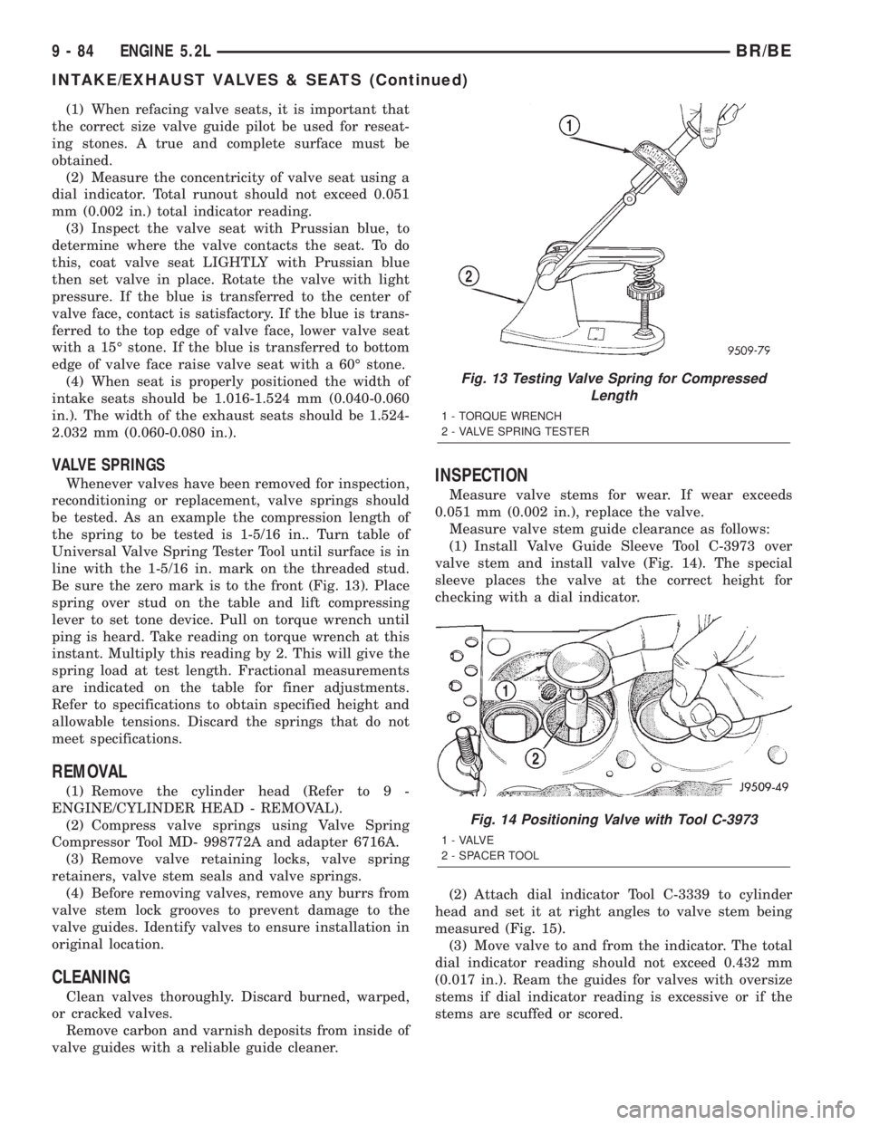
Be sure the zero mark is to the front (Fig. 13). Place
spring over stud on the table and lift compressing
lever to set tone device. Pull on torque wrench until
ping is heard. Take reading on torque wrench at this
instant. Multiply this reading by 2. This will give the
spring load at test length. Fractional measurements
are indicated on the table for finer adjustments.
Refer to specifications to obtain specified height and
allowable tensions. Discard the springs that do not
meet specifications.
REMOVAL
(1) Remove the cylinder head (Refer to 9 -
ENGINE/CYLINDER HEAD - REMOVAL).
(2) Compress valve springs using Valve Spring
Compressor Tool MD- 998772A and adapter 6716A.
(3) Remove valve retaining locks, valve spring
retainers, valve stem seals and valve springs.
(4) Before removing valves, remove any burrs from
valve stem lock grooves to prevent damage to the
valve guides. Identify valves to ensure installation in
original location.
CLEANING
Clean valves thoroughly. Discard burned, warped,
or cracked valves.
Remove carbon and varnish deposits from inside of
valve guides with a reliable guide cleaner.
INSPECTION
Measure valve stems for wear. If wear exceeds
0.051 mm (0.002 in.), replace the valve.
Measure valve stem guide clearance as follows:
(1) Install Valve Guide Sleeve Tool C-3973 over
valve stem and install valve (Fig. 14). The special
sleeve places the valve at the correct height for
checking with a dial indicator.
(2) Attach dial indicator Tool C-3339 to cylinder
head and set it at right angles to valve stem being
measured (Fig. 15).
(3) Move valve to and from the indicator. The total
dial indicator reading should not exceed 0.432 mm
(0.017 in.). Ream the guides for valves with oversize
stems if dial indicator reading is excessive or if the
stems are scuffed or scored.
Fig. 13 Testing Valve Spring for Compressed
Length
1 - TORQUE WRENCH
2 - VALVE SPRING TESTER
Fig. 14 Positioning Valve with Tool C-3973
1 - VALVE
2 - SPACER TOOL
9 - 84 ENGINE 5.2LBR/BE
INTAKE/EXHAUST VALVES & SEATS (Continued)
Page 1287 of 2889
VALVES
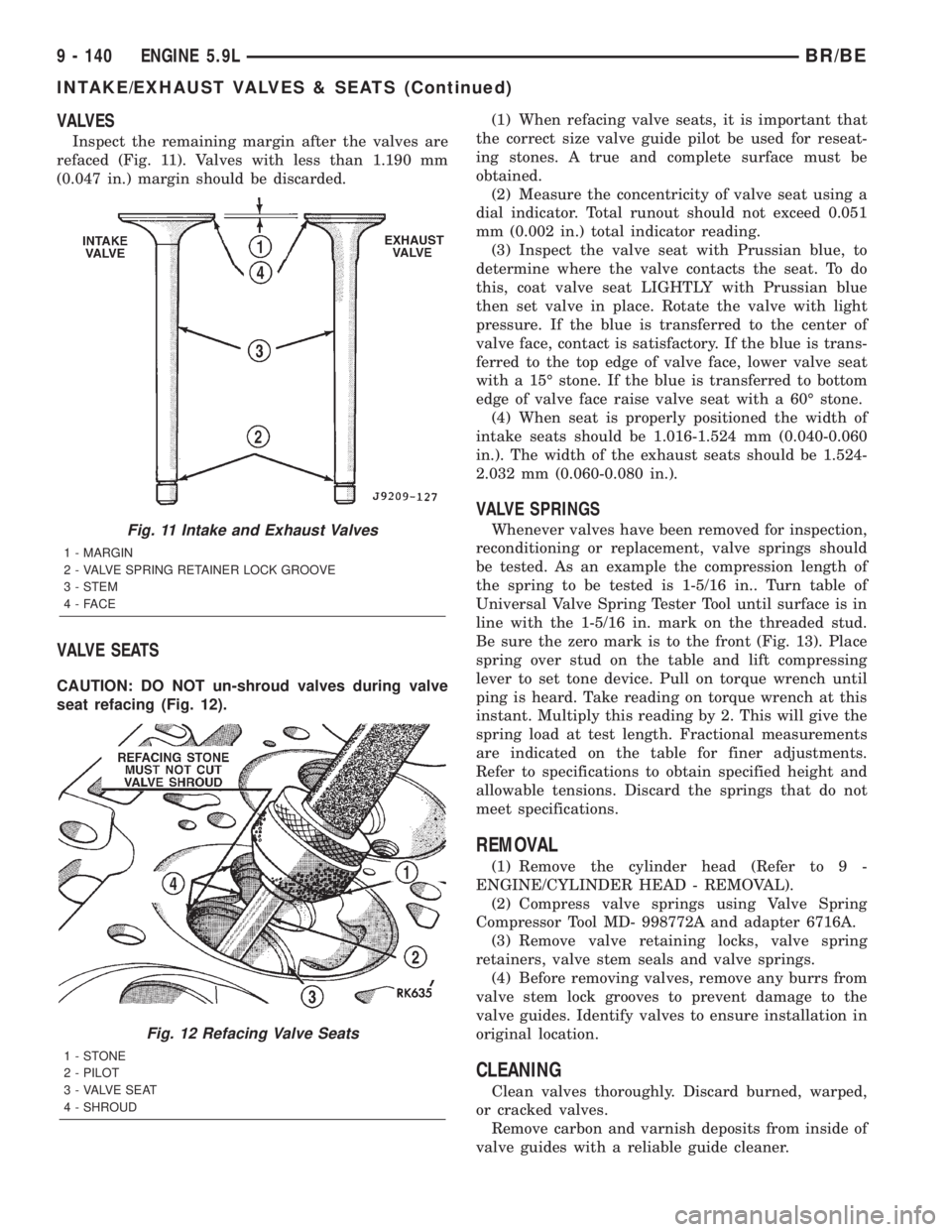
Inspect the remaining margin after the valves are
refaced (Fig. 11). Valves with less than 1.190 mm
(0.047 in.) margin should be discarded.
VALVE SEATS
CAUTION: DO NOT un-shroud valves during valve
seat refacing (Fig. 12).(1) When refacing valve seats, it is important that
the correct size valve guide pilot be used for reseat-
ing stones. A true and complete surface must be
obtained.
(2) Measure the concentricity of valve seat using a
dial indicator. Total runout should not exceed 0.051
mm (0.002 in.) total indicator reading.
(3) Inspect the valve seat with Prussian blue, to
determine where the valve contacts the seat. To do
this, coat valve seat LIGHTLY with Prussian blue
then set valve in place. Rotate the valve with light
pressure. If the blue is transferred to the center of
valve face, contact is satisfactory. If the blue is trans-
ferred to the top edge of valve face, lower valve seat
with a 15É stone. If the blue is transferred to bottom
edge of valve face raise valve seat with a 60É stone.
(4) When seat is properly positioned the width of
intake seats should be 1.016-1.524 mm (0.040-0.060
in.). The width of the exhaust seats should be 1.524-
2.032 mm (0.060-0.080 in.).
VALVE SPRINGS
Whenever valves have been removed for inspection,
reconditioning or replacement, valve springs should
be tested. As an example the compression length of
the spring to be tested is 1-5/16 in.. Turn table of
Universal Valve Spring Tester Tool until surface is in
line with the 1-5/16 in. mark on the threaded stud.
Be sure the zero mark is to the front (Fig. 13). Place
spring over stud on the table and lift compressing
lever to set tone device. Pull on torque wrench until
ping is heard. Take reading on torque wrench at this
instant. Multiply this reading by 2. This will give the
spring load at test length. Fractional measurements
are indicated on the table for finer adjustments.
Refer to specifications to obtain specified height and
allowable tensions. Discard the springs that do not
meet specifications.
REMOVAL
(1) Remove the cylinder head (Refer to 9 -
ENGINE/CYLINDER HEAD - REMOVAL).
(2) Compress valve springs using Valve Spring
Compressor Tool MD- 998772A and adapter 6716A.
(3) Remove valve retaining locks, valve spring
retainers, valve stem seals and valve springs.
(4) Before removing valves, remove any burrs from
valve stem lock grooves to prevent damage to the
valve guides. Identify valves to ensure installation in
original location.
CLEANING
Clean valves thoroughly. Discard burned, warped,
or cracked valves.
Remove carbon and varnish deposits from inside of
valve guides with a reliable guide cleaner.
Fig. 11 Intake and Exhaust Valves
1 - MARGIN
2 - VALVE SPRING RETAINER LOCK GROOVE
3 - STEM
4-FACE
Fig. 12 Refacing Valve Seats
1-STONE
2 - PILOT
3 - VALVE SEAT
4 - SHROUD
9 - 140 ENGINE 5.9LBR/BE
INTAKE/EXHAUST VALVES & SEATS (Continued)
Page 1344 of 2889
(3) Inspect the valve seat with Prussian blue to
determine where the valve contacts the seat. To do
this, coat valve seat LIGHTLY with Prussian blue
then set valve in place. Rotate the valve with light
pressure. If the blue is transferred to the center of
valve face, contact is satisfactory. If the blue is trans-
ferred to the top edge of valve face, lower valve seat
with a 15É stone. If the blue is transferred to bottom
edge of valve face raise valve seat with a 60É stone.
(4) When seat is properly positioned the width of
valve seats should be 1.016-1.524 mm (0.040-0.060
inch).
VALVE SPRING INSPECTION
Whenever valves have been removed for inspection,
reconditioning or replacement, valve springs should
be tested. As an example the compression length of
the spring to be tested is 1-5/16 inch. Turn table of
Universal Valve Spring Tester Tool until surface is in
line with the 1-5/16 inch mark on the threaded stud.
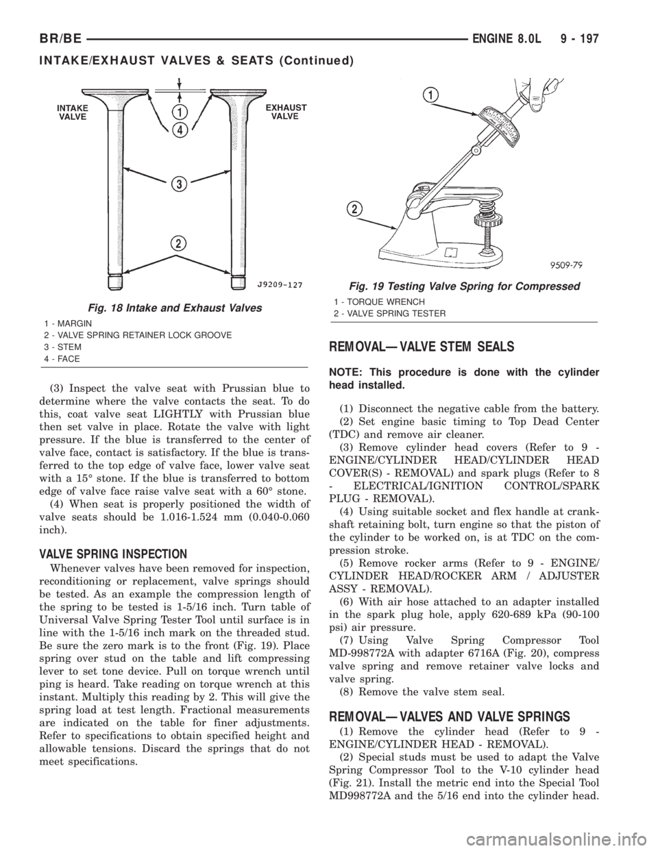
Be sure the zero mark is to the front (Fig. 19). Place
spring over stud on the table and lift compressing
lever to set tone device. Pull on torque wrench until
ping is heard. Take reading on torque wrench at this
instant. Multiply this reading by 2. This will give the
spring load at test length. Fractional measurements
are indicated on the table for finer adjustments.
Refer to specifications to obtain specified height and
allowable tensions. Discard the springs that do not
meet specifications.
REMOVALÐVALVE STEM SEALS
NOTE: This procedure is done with the cylinder
head installed.
(1) Disconnect the negative cable from the battery.
(2) Set engine basic timing to Top Dead Center
(TDC) and remove air cleaner.
(3) Remove cylinder head covers (Refer to 9 -
ENGINE/CYLINDER HEAD/CYLINDER HEAD
COVER(S) - REMOVAL) and spark plugs (Refer to 8
- ELECTRICAL/IGNITION CONTROL/SPARK
PLUG - REMOVAL).
(4) Using suitable socket and flex handle at crank-
shaft retaining bolt, turn engine so that the piston of
the cylinder to be worked on, is at TDC on the com-
pression stroke.
(5) Remove rocker arms (Refer to 9 - ENGINE/
CYLINDER HEAD/ROCKER ARM / ADJUSTER
ASSY - REMOVAL).
(6) With air hose attached to an adapter installed
in the spark plug hole, apply 620-689 kPa (90-100
psi) air pressure.
(7) Using Valve Spring Compressor Tool
MD-998772A with adapter 6716A (Fig. 20), compress
valve spring and remove retainer valve locks and
valve spring.
(8) Remove the valve stem seal.
REMOVALÐVALVES AND VALVE SPRINGS
(1) Remove the cylinder head (Refer to 9 -
ENGINE/CYLINDER HEAD - REMOVAL).
(2) Special studs must be used to adapt the Valve
Spring Compressor Tool to the V-10 cylinder head
(Fig. 21). Install the metric end into the Special Tool
MD998772A and the 5/16 end into the cylinder head.
Fig. 18 Intake and Exhaust Valves
1 - MARGIN
2 - VALVE SPRING RETAINER LOCK GROOVE
3 - STEM
4-FACE
Fig. 19 Testing Valve Spring for Compressed
1 - TORQUE WRENCH
2 - VALVE SPRING TESTER
BR/BEENGINE 8.0L 9 - 197
INTAKE/EXHAUST VALVES & SEATS (Continued)
Page 1376 of 2889
ENGINE 5.9L DIESEL
TABLE OF CONTENTS
page page
ENGINE 5.9L DIESEL
DESCRIPTION..........................231
DIAGNOSIS AND TESTING................232
ENGINE DIAGNOSIS - MECHANICAL.......232
SMOKE DIAGNOSIS CHARTS............234
STANDARD PROCEDURE.................237
FORM-IN-PLACE GASKETS AND SEALERS . . 237
REPAIR DAMAGED OR WORN THREADS . . . 238
HYDROSTATIC LOCK...................238
REMOVAL.............................238
INSTALLATION..........................241
SPECIFICATIONS........................242
SPECIAL TOOLS........................244
ENGINE DATA PLATE
DESCRIPTION..........................244
AIR CLEANER ELEMENT
REMOVAL.............................244
INSTALLATION..........................245
CYLINDER HEAD
DESCRIPTION..........................246
REMOVAL.............................246
CLEANING.............................248
INSPECTION...........................250
INSTALLATION..........................250
CYLINDER HEAD COVER(S)
REMOVAL.............................253
CLEANING.............................253
INSPECTION...........................253
INSTALLATION..........................253
INTAKE/EXHAUST VALVES & SEATS
DESCRIPTION..........................253
STANDARD PROCEDURE.................253
VALVES, GUIDES AND SPRINGS..........253
VALVE LASH ADJUSTMENT AND
VERIFICATION........................256
REMOVAL.............................258
INSTALLATION..........................260
ROCKER ARM / ADJUSTER ASSY
DESCRIPTION..........................261
REMOVAL.............................261
CLEANING.............................262
INSPECTION...........................262
INSTALLATION..........................263
ENGINE BLOCK
STANDARD PROCEDURE.................263
CYLINDER BORE REFACING.............263
CYLINDER BORE DE-GLAZE.............264
CYLINDER BORE REPAIR...............265
CAM BORE REPAIR....................267INSPECTION...........................267
CAMSHAFT & BEARINGS (IN BLOCK)
REMOVAL.............................268
INSPECTION...........................272
INSTALLATION..........................273
CONNECTING ROD BEARINGS
STANDARD PROCEDURE.................274
CONNECTING ROD BEARING AND
CRANKSHAFT JOURNAL CLEARANCE......274
CRANKSHAFT
DESCRIPTION..........................275
CRANKSHAFT MAIN BEARINGS
STANDARD PROCEDURE.................275
MAIN BEARING CLEARANCE............275
CRANKSHAFT OIL SEAL - FRONT
REMOVAL.............................276
INSTALLATION..........................277
CRANKSHAFT OIL SEAL - REAR
REMOVAL.............................278
INSTALLATION..........................278
CRANKSHAFT REAR OIL SEAL RETAINER
REMOVAL.............................278
INSTALLATION..........................279
SOLID LIFTERS/TAPPETS
REMOVAL.............................280
CLEANING.............................281
INSPECTION...........................281
INSTALLATION..........................281
PISTON & CONNECTING ROD
DESCRIPTION..........................282
STANDARD PROCEDURE.................282
PISTON GRADING....................282
REMOVAL.............................285
CLEANING.............................285
INSPECTION...........................285
INSTALLATION..........................287
PISTON RINGS
STANDARD PROCEDURE.................288
PISTON RINGS - FITTING...............288
VIBRATION DAMPER
REMOVAL.............................289
INSPECTION...........................289
INSTALLATION..........................289
FRONT MOUNT
REMOVAL.............................290
INSTALLATION..........................290
REAR MOUNT
REMOVAL.............................291
INSTALLATION..........................291
BR/BEENGINE 5.9L DIESEL 9 - 229
Page 1383 of 2889
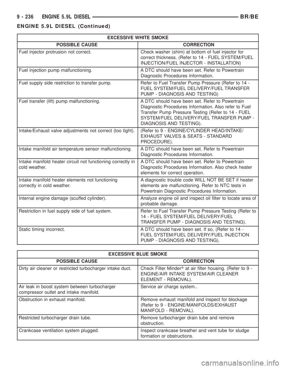
EXCESSIVE WHITE SMOKE
POSSIBLE CAUSE CORRECTION
Fuel injector protrusion not correct. Check washer (shim) at bottom of fuel injector for
correct thickness. (Refer to 14 - FUEL SYSTEM/FUEL
INJECTION/FUEL INJECTOR - INSTALLATION)
Fuel injection pump malfunctioning. A DTC should have been set. Refer to Powertrain
Diagnostic Procedures Information.
Fuel supply side restriction to transfer pump. Refer to Fuel Transfer Pump Pressure (Refer to 14 -
FUEL SYSTEM/FUEL DELIVERY/FUEL TRANSFER
PUMP - DIAGNOSIS AND TESTING)
Fuel transfer (lift) pump malfunctioning. A DTC should have been set. Refer to Powertrain
Diagnostic Procedures Information. Also refer to Fuel
Transfer Pump Pressure Testing (Refer to 14 - FUEL
SYSTEM/FUEL DELIVERY/FUEL TRANSFER PUMP -
DIAGNOSIS AND TESTING).
Intake/Exhaust valve adjustments not correct (too tight). (Refer to 9 - ENGINE/CYLINDER HEAD/INTAKE/
EXHAUST VALVES & SEATS - STANDARD
PROCEDURE).
Intake manifold air temperature sensor malfunctioning. A DTC should have been set. Refer to Powertrain
Diagnostic Procedures Information.
Intake manifold heater circuit not functioning correctly in
cold weather.A DTC should have been set. Refer to Powertrain
Diagnostic Procedures Information. Also check heater
elements for correct operation.
Intake manifold heater elements not functioning
correctly in cold weather.A diagnostic trouble code WILL NOT BE SET if heater
elements are malfunctioning. Refer to NTC tests in
Powertrain Diagnostic Procedures Information.
Internal engine damage (scuffed cylinder). Analyze engine oil and inspect oil filter to locate area of
probable damage.
Restriction in fuel supply side of fuel system. Refer to Fuel Transfer Pump Pressure Testing (Refer to
14 - FUEL SYSTEM/FUEL DELIVERY/FUEL
TRANSFER PUMP - DIAGNOSIS AND TESTING).
Static timing incorrect. A DTC should have been set. If so, (Refer to 14 -
FUEL SYSTEM/FUEL DELIVERY/FUEL INJECTION
PUMP - DIAGNOSIS AND TESTING).
EXCESSIVE BLUE SMOKE
POSSIBLE CAUSE CORRECTION
Dirty air cleaner or restricted turbocharger intake duct. Check Filter MinderTat air filter housing. (Refer to 9 -
ENGINE/AIR INTAKE SYSTEM/AIR CLEANER
ELEMENT - REMOVAL).
Air leak in boost system between turbocharger
compressor outlet and intake manifold.Service air charge system..
Obstruction in exhaust manifold. Remove exhaust manifold and inspect for blockage
(Refer to 9 - ENGINE/MANIFOLDS/EXHAUST
MANIFOLD - REMOVAL).
Restricted turbocharger drain tube. Remove turbocharger drain tube and remove
obstruction.
Crankcase ventilation system plugged. Inspect crankcase breather and vent tube for sludge
formation or obstructions.
9 - 236 ENGINE 5.9L DIESELBR/BE
ENGINE 5.9L DIESEL (Continued)
Page 1403 of 2889
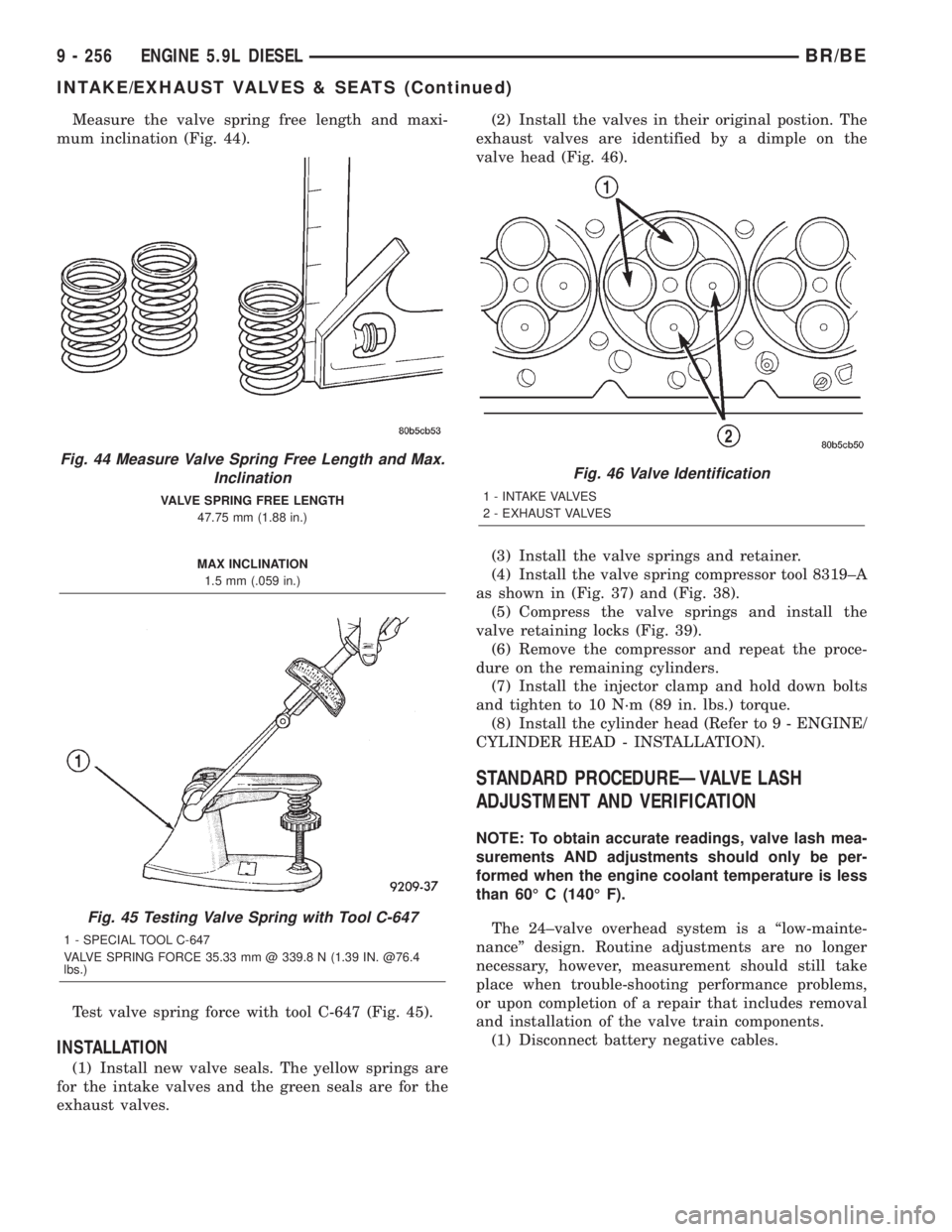
Measure the valve spring free length and maxi-
mum inclination (Fig. 44).
Test valve spring force with tool C-647 (Fig. 45).
INSTALLATION
(1) Install new valve seals. The yellow springs are
for the intake valves and the green seals are for the
exhaust valves.(2) Install the valves in their original postion. The
exhaust valves are identified by a dimple on the
valve head (Fig. 46).
(3) Install the valve springs and retainer.
(4) Install the valve spring compressor tool 8319±A
as shown in (Fig. 37) and (Fig. 38).
(5) Compress the valve springs and install the
valve retaining locks (Fig. 39).
(6) Remove the compressor and repeat the proce-
dure on the remaining cylinders.
(7) Install the injector clamp and hold down bolts
and tighten to 10 N´m (89 in. lbs.) torque.
(8) Install the cylinder head (Refer to 9 - ENGINE/
CYLINDER HEAD - INSTALLATION).
STANDARD PROCEDUREÐVALVE LASH
ADJUSTMENT AND VERIFICATION
NOTE: To obtain accurate readings, valve lash mea-
surements AND adjustments should only be per-
formed when the engine coolant temperature is less
than 60É C (140É F).
The 24±valve overhead system is a ªlow-mainte-
nanceº design. Routine adjustments are no longer
necessary, however, measurement should still take
place when trouble-shooting performance problems,
or upon completion of a repair that includes removal
and installation of the valve train components.
(1) Disconnect battery negative cables.
Fig. 44 Measure Valve Spring Free Length and Max.
Inclination
VALVE SPRING FREE LENGTH
47.75 mm (1.88 in.)
MAX INCLINATION
1.5 mm (.059 in.)
Fig. 45 Testing Valve Spring with Tool C-647
1 - SPECIAL TOOL C-647
VALVE SPRING FORCE 35.33 mm @ 339.8 N (1.39 IN. @76.4
lbs.)
Fig. 46 Valve Identification
1 - INTAKE VALVES
2 - EXHAUST VALVES
9 - 256 ENGINE 5.9L DIESELBR/BE
INTAKE/EXHAUST VALVES & SEATS (Continued)
Page 1404 of 2889
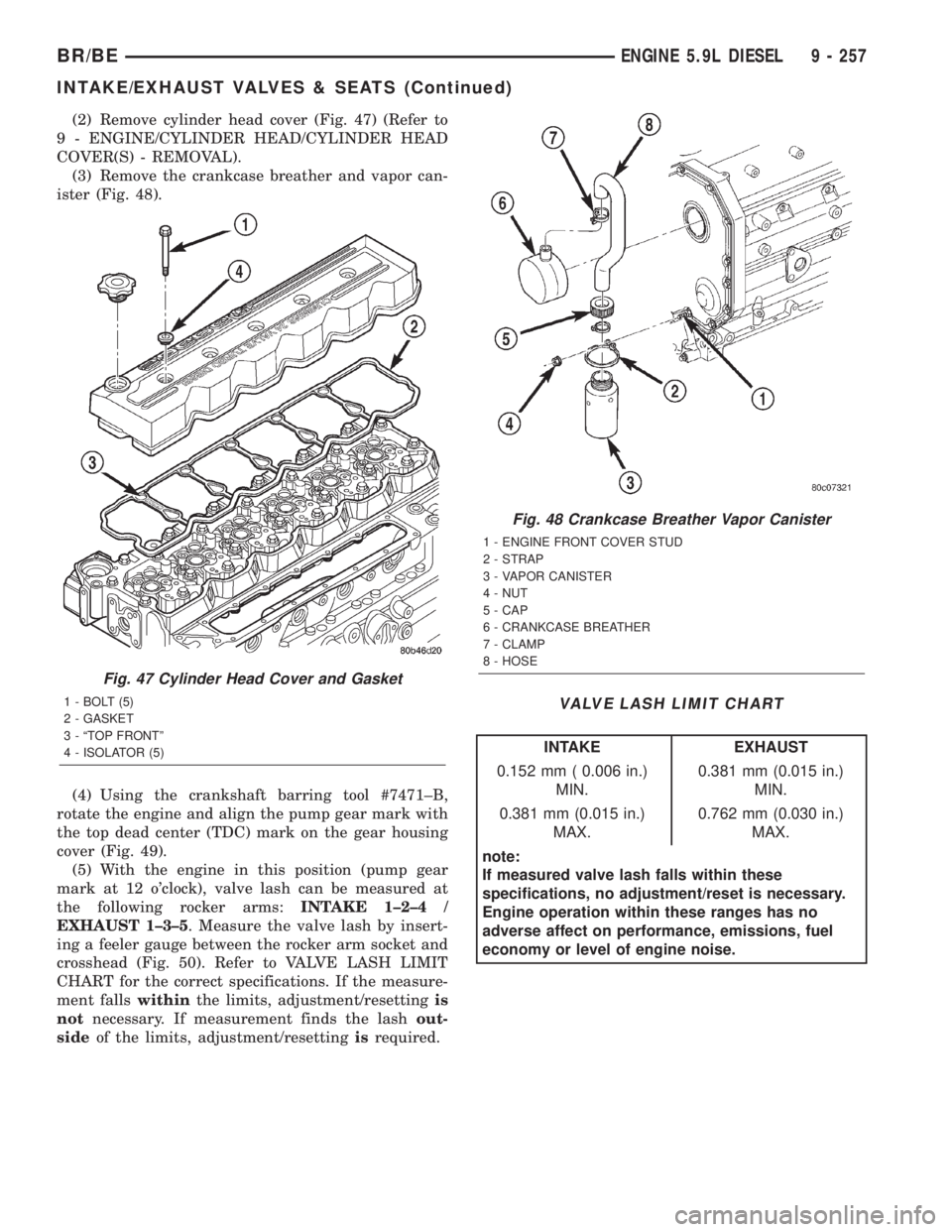
(2) Remove cylinder head cover (Fig. 47) (Refer to
9 - ENGINE/CYLINDER HEAD/CYLINDER HEAD
COVER(S) - REMOVAL).
(3) Remove the crankcase breather and vapor can-
ister (Fig. 48).
(4) Using the crankshaft barring tool #7471±B,
rotate the engine and align the pump gear mark with
the top dead center (TDC) mark on the gear housing
cover (Fig. 49).
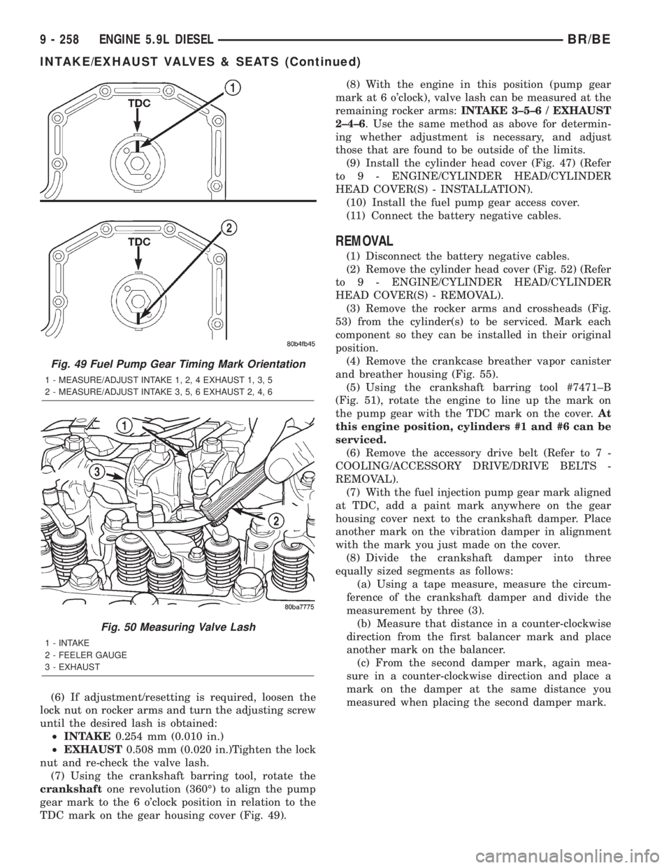
(5) With the engine in this position (pump gear
mark at 12 o'clock), valve lash can be measured at
the following rocker arms:INTAKE 1±2±4 /
EXHAUST 1±3±5. Measure the valve lash by insert-
ing a feeler gauge between the rocker arm socket and
crosshead (Fig. 50). Refer to VALVE LASH LIMIT
CHART for the correct specifications. If the measure-
ment fallswithinthe limits, adjustment/resettingis
notnecessary. If measurement finds the lashout-
sideof the limits, adjustment/resettingisrequired.
VALVE LASH LIMIT CHART
INTAKE EXHAUST
0.152 mm ( 0.006 in.)
MIN.0.381 mm (0.015 in.)
MIN.
0.381 mm (0.015 in.)
MAX.0.762 mm (0.030 in.)
MAX.
note:
If measured valve lash falls within these
specifications, no adjustment/reset is necessary.
Engine operation within these ranges has no
adverse affect on performance, emissions, fuel
economy or level of engine noise.
Fig. 47 Cylinder Head Cover and Gasket
1 - BOLT (5)
2 - GASKET
3 - ªTOP FRONTº
4 - ISOLATOR (5)
Fig. 48 Crankcase Breather Vapor Canister
1 - ENGINE FRONT COVER STUD
2 - STRAP
3 - VAPOR CANISTER
4 - NUT
5 - CAP
6 - CRANKCASE BREATHER
7 - CLAMP
8 - HOSE
BR/BEENGINE 5.9L DIESEL 9 - 257
INTAKE/EXHAUST VALVES & SEATS (Continued)
Page 1405 of 2889
(6) If adjustment/resetting is required, loosen the
lock nut on rocker arms and turn the adjusting screw
until the desired lash is obtained:
²INTAKE0.254 mm (0.010 in.)
²EXHAUST0.508 mm (0.020 in.)Tighten the lock
nut and re-check the valve lash.
(7) Using the crankshaft barring tool, rotate the
crankshaftone revolution (360É) to align the pump
gear mark to the 6 o'clock position in relation to the
TDC mark on the gear housing cover (Fig. 49).(8) With the engine in this position (pump gear
mark at 6 o'clock), valve lash can be measured at the
remaining rocker arms:INTAKE 3±5±6 / EXHAUST
2±4±6. Use the same method as above for determin-
ing whether adjustment is necessary, and adjust
those that are found to be outside of the limits.
(9) Install the cylinder head cover (Fig. 47) (Refer
to 9 - ENGINE/CYLINDER HEAD/CYLINDER
HEAD COVER(S) - INSTALLATION).
(10) Install the fuel pump gear access cover.
(11) Connect the battery negative cables.
REMOVAL
(1) Disconnect the battery negative cables.
(2) Remove the cylinder head cover (Fig. 52) (Refer
to 9 - ENGINE/CYLINDER HEAD/CYLINDER
HEAD COVER(S) - REMOVAL).
(3) Remove the rocker arms and crossheads (Fig.
53) from the cylinder(s) to be serviced. Mark each
component so they can be installed in their original
position.
(4) Remove the crankcase breather vapor canister
and breather housing (Fig. 55).
(5) Using the crankshaft barring tool #7471±B
(Fig. 51), rotate the engine to line up the mark on
the pump gear with the TDC mark on the cover.At
this engine position, cylinders #1 and #6 can be
serviced.
(6) Remove the accessory drive belt (Refer to 7 -
COOLING/ACCESSORY DRIVE/DRIVE BELTS -
REMOVAL).
(7) With the fuel injection pump gear mark aligned
at TDC, add a paint mark anywhere on the gear
housing cover next to the crankshaft damper. Place
another mark on the vibration damper in alignment
with the mark you just made on the cover.
(8) Divide the crankshaft damper into three
equally sized segments as follows:
(a) Using a tape measure, measure the circum-
ference of the crankshaft damper and divide the
measurement by three (3).
(b) Measure that distance in a counter-clockwise
direction from the first balancer mark and place
another mark on the balancer.
(c) From the second damper mark, again mea-
sure in a counter-clockwise direction and place a
mark on the damper at the same distance you
measured when placing the second damper mark.
Fig. 49 Fuel Pump Gear Timing Mark Orientation
1 - MEASURE/ADJUST INTAKE 1, 2, 4 EXHAUST 1, 3, 5
2 - MEASURE/ADJUST INTAKE 3, 5, 6 EXHAUST 2, 4, 6
Fig. 50 Measuring Valve Lash
1 - INTAKE
2 - FEELER GAUGE
3 - EXHAUST
9 - 258 ENGINE 5.9L DIESELBR/BE
INTAKE/EXHAUST VALVES & SEATS (Continued)
Page 1408 of 2889
(4)Verify valve lash adjustment (Refer to 9 -
ENGINE/CYLINDER HEAD/INTAKE/EXHAUST
VALVES & SEATS - STANDARD PROCEDURE).
(5) Install cylinder head cover and reusable gasket
(Fig. 52) (Refer to 9 - ENGINE/CYLINDER HEAD/
CYLINDER HEAD COVER(S) - INSTALLATION).
(6) Install the accessory drive belt (Refer to 7 -
COOLING/ACCESSORY DRIVE/DRIVE BELTS -
INSTALLATION).
(7) Connect battery negative cables.
ROCKER ARM / ADJUSTER
ASSY
DESCRIPTION
The 24±valve overhead system incorporates rocker
arms that are designed to allow fuel injector service
without removing the rocker arms and pedestals. The
unique intake and exhaust rocker arms have their
own rocker shafts and are lubricated by passages
intersecting the cylinder block main oil rifle. Cross-
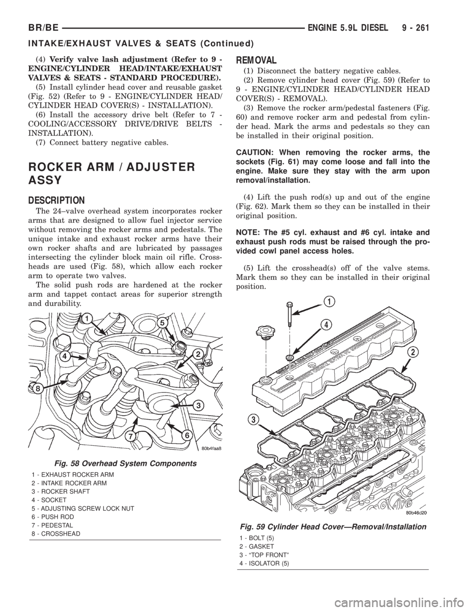
heads are used (Fig. 58), which allow each rocker
arm to operate two valves.
The solid push rods are hardened at the rocker
arm and tappet contact areas for superior strength
and durability.
REMOVAL
(1) Disconnect the battery negative cables.
(2) Remove cylinder head cover (Fig. 59) (Refer to
9 - ENGINE/CYLINDER HEAD/CYLINDER HEAD
COVER(S) - REMOVAL).
(3) Remove the rocker arm/pedestal fasteners (Fig.
60) and remove rocker arm and pedestal from cylin-
der head. Mark the arms and pedestals so they can
be installed in their original position.
CAUTION: When removing the rocker arms, the
sockets (Fig. 61) may come loose and fall into the
engine. Make sure they stay with the arm upon
removal/installation.
(4) Lift the push rod(s) up and out of the engine
(Fig. 62). Mark them so they can be installed in their
original position.
NOTE: The #5 cyl. exhaust and #6 cyl. intake and
exhaust push rods must be raised through the pro-
vided cowl panel access holes.
(5) Lift the crosshead(s) off of the valve stems.
Mark them so they can be installed in their original
position.
Fig. 58 Overhead System Components
1 - EXHAUST ROCKER ARM
2 - INTAKE ROCKER ARM
3 - ROCKER SHAFT
4 - SOCKET
5 - ADJUSTING SCREW LOCK NUT
6 - PUSH ROD
7 - PEDESTAL
8 - CROSSHEAD
Fig. 59 Cylinder Head CoverÐRemoval/Installation
1 - BOLT (5)
2 - GASKET
3 - ªTOP FRONTº
4 - ISOLATOR (5)
BR/BEENGINE 5.9L DIESEL 9 - 261
INTAKE/EXHAUST VALVES & SEATS (Continued)
Page 1410 of 2889
Push Rods
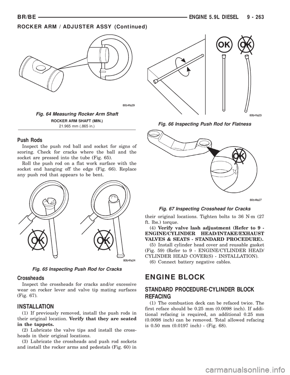
Inspect the push rod ball and socket for signs of
scoring. Check for cracks where the ball and the
socket are pressed into the tube (Fig. 65).
Roll the push rod on a flat work surface with the
socket end hanging off the edge (Fig. 66). Replace
any push rod that appears to be bent.
Crossheads
Inspect the crossheads for cracks and/or excessive
wear on rocker lever and valve tip mating surfaces
(Fig. 67).
INSTALLATION
(1) If previously removed, install the push rods in
their original location.Verify that they are seated
in the tappets.
(2) Lubricate the valve tips and install the cross-
heads in their original locations.
(3) Lubricate the crossheads and push rod sockets
and install the rocker arms and pedestals (Fig. 60) intheir original locations. Tighten bolts to 36 N´m (27
ft. lbs.) torque.
(4)Verify valve lash adjustment (Refer to 9 -
ENGINE/CYLINDER HEAD/INTAKE/EXHAUST
VALVES & SEATS - STANDARD PROCEDURE).
(5) Install cylinder head cover and reusable gasket
(Fig. 59) (Refer to 9 - ENGINE/CYLINDER HEAD/
CYLINDER HEAD COVER(S) - INSTALLATION).
(6) Connect battery negative cables.
ENGINE BLOCK
STANDARD PROCEDURE-CYLINDER BLOCK
REFACING
(1) The combustion deck can be refaced twice. The
first reface should be 0.25 mm (0.0098 inch). If addi-
tional refacing is required, an additional 0.25 mm
(0.0098 inch) can be removed. Total allowed refacing
is 0.50 mm (0.0197 inch) - (Fig. 68).
Fig. 64 Measuring Rocker Arm Shaft
ROCKER ARM SHAFT (MIN.)
21.965 mm (.865 in.)
Fig. 65 Inspecting Push Rod for Cracks
Fig. 66 Inspecting Push Rod for Flatness
Fig. 67 Inspecting Crosshead for Cracks
BR/BEENGINE 5.9L DIESEL 9 - 263
ROCKER ARM / ADJUSTER ASSY (Continued)