Temperature sensor location DODGE RAM 2001 Service Repair Manual
[x] Cancel search | Manufacturer: DODGE, Model Year: 2001, Model line: RAM, Model: DODGE RAM 2001Pages: 2889, PDF Size: 68.07 MB
Page 464 of 2889
ENGINE CONTROL MODULE
DESCRIPTION - ECM
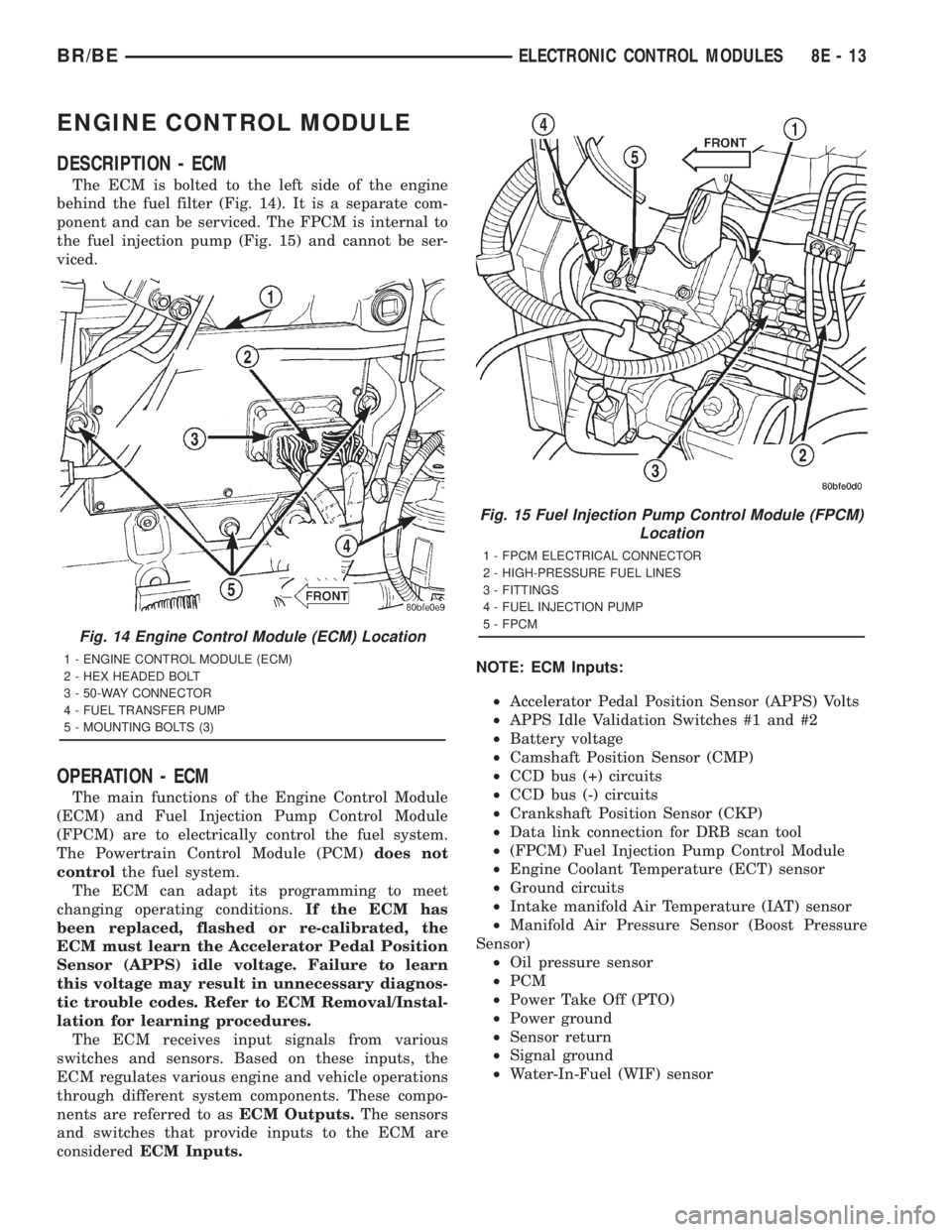
The ECM is bolted to the left side of the engine
behind the fuel filter (Fig. 14). It is a separate com-
ponent and can be serviced. The FPCM is internal to
the fuel injection pump (Fig. 15) and cannot be ser-
viced.
OPERATION - ECM
The main functions of the Engine Control Module
(ECM) and Fuel Injection Pump Control Module
(FPCM) are to electrically control the fuel system.
The Powertrain Control Module (PCM)does not
controlthe fuel system.
The ECM can adapt its programming to meet
changing operating conditions.If the ECM has
been replaced, flashed or re-calibrated, the
ECM must learn the Accelerator Pedal Position
Sensor (APPS) idle voltage. Failure to learn
this voltage may result in unnecessary diagnos-
tic trouble codes. Refer to ECM Removal/Instal-
lation for learning procedures.
The ECM receives input signals from various
switches and sensors. Based on these inputs, the
ECM regulates various engine and vehicle operations
through different system components. These compo-
nents are referred to asECM Outputs.The sensors
and switches that provide inputs to the ECM are
consideredECM Inputs.NOTE: ECM Inputs:
²Accelerator Pedal Position Sensor (APPS) Volts
²APPS Idle Validation Switches #1 and #2
²Battery voltage
²Camshaft Position Sensor (CMP)
²CCD bus (+) circuits
²CCD bus (-) circuits
²Crankshaft Position Sensor (CKP)
²Data link connection for DRB scan tool
²(FPCM) Fuel Injection Pump Control Module
²Engine Coolant Temperature (ECT) sensor
²Ground circuits
²Intake manifold Air Temperature (IAT) sensor
²Manifold Air Pressure Sensor (Boost Pressure
Sensor)
²Oil pressure sensor
²PCM
²Power Take Off (PTO)
²Power ground
²Sensor return
²Signal ground
²Water-In-Fuel (WIF) sensor
Fig. 14 Engine Control Module (ECM) Location
1 - ENGINE CONTROL MODULE (ECM)
2 - HEX HEADED BOLT
3 - 50-WAY CONNECTOR
4 - FUEL TRANSFER PUMP
5 - MOUNTING BOLTS (3)
Fig. 15 Fuel Injection Pump Control Module (FPCM)
Location
1 - FPCM ELECTRICAL CONNECTOR
2 - HIGH-PRESSURE FUEL LINES
3 - FITTINGS
4 - FUEL INJECTION PUMP
5 - FPCM
BR/BEELECTRONIC CONTROL MODULES 8E - 13
Page 466 of 2889
During Open Loop modes, the PCM receives input
signals and responds only according to preset PCM
programming. Input from the oxygen (O2S) sensors
is not monitored during Open Loop modes.
During Closed Loop modes, the PCM will monitor
the oxygen (O2S) sensors input. This input indicates
to the PCM whether or not the calculated injector
pulse width results in the ideal air-fuel ratio. This
ratio is 14.7 parts air-to-1 part fuel. By monitoring
the exhaust oxygen content through the O2S sensor,
the PCM can fine tune the injector pulse width. This
is done to achieve optimum fuel economy combined
with low emission engine performance.
The fuel injection system has the following modes
of operation:
²Ignition switch ON
²Engine start-up (crank)
²Engine warm-up
²Idle
²Cruise
²Acceleration
²Deceleration
²Wide open throttle (WOT)
²Ignition switch OFF
The ignition switch On, engine start-up (crank),
engine warm-up, acceleration, deceleration and wide
open throttle modes are Open Loop modes. The idle
and cruise modes, (with the engine at operating tem-
perature) are Closed Loop modes.
IGNITION SWITCH (KEY-ON) MODE
This is an Open Loop mode. When the fuel system
is activated by the ignition switch, the following
actions occur:²The PCM pre-positions the idle air control (IAC)
motor.
²The PCM determines atmospheric air pressure
from the MAP sensor input to determine basic fuel
strategy.
²The PCM monitors the engine coolant tempera-
ture sensor input. The PCM modifies fuel strategy
based on this input.
²Intake manifold air temperature sensor input is
monitored.
²Throttle position sensor (TPS) is monitored.
²The auto shutdown (ASD) relay is energized by
the PCM for approximately three seconds.
²The fuel pump is energized through the fuel
pump relay by the PCM. The fuel pump will operate
for approximately three seconds unless the engine is
operating or the starter motor is engaged.
²The O2S sensor heater element is energized via
the ASD relay. The O2S sensor input is not used by
the PCM to calibrate air-fuel ratio during this mode
of operation.
ENGINE START-UP MODE
This is an Open Loop mode. The following actions
occur when the starter motor is engaged.
The PCM receives inputs from:
²Battery voltage
²Engine coolant temperature sensor
²Crankshaft position sensor
²Intake manifold air temperature sensor
²Manifold absolute pressure (MAP) sensor
²Throttle position sensor (TPS)
²Starter motor relay
²Camshaft position sensor signal
The PCM monitors the crankshaft position sensor.
If the PCM does not receive a crankshaft position
sensor signal within 3 seconds of cranking the
engine, it will shut down the fuel injection system.
The fuel pump is activated by the PCM through
the fuel pump relay.
Voltage is applied to the fuel injectors with the
ASD relay via the PCM. The PCM will then control
the injection sequence and injector pulse width by
turning the ground circuit to each individual injector
on and off.
The PCM determines the proper ignition timing
according to input received from the crankshaft posi-
tion sensor.
ENGINE WARM-UP MODE
This is an Open Loop mode. During engine warm-
up, the PCM receives inputs from:
²Battery voltage
²Crankshaft position sensor
²Engine coolant temperature sensor
²Intake manifold air temperature sensor
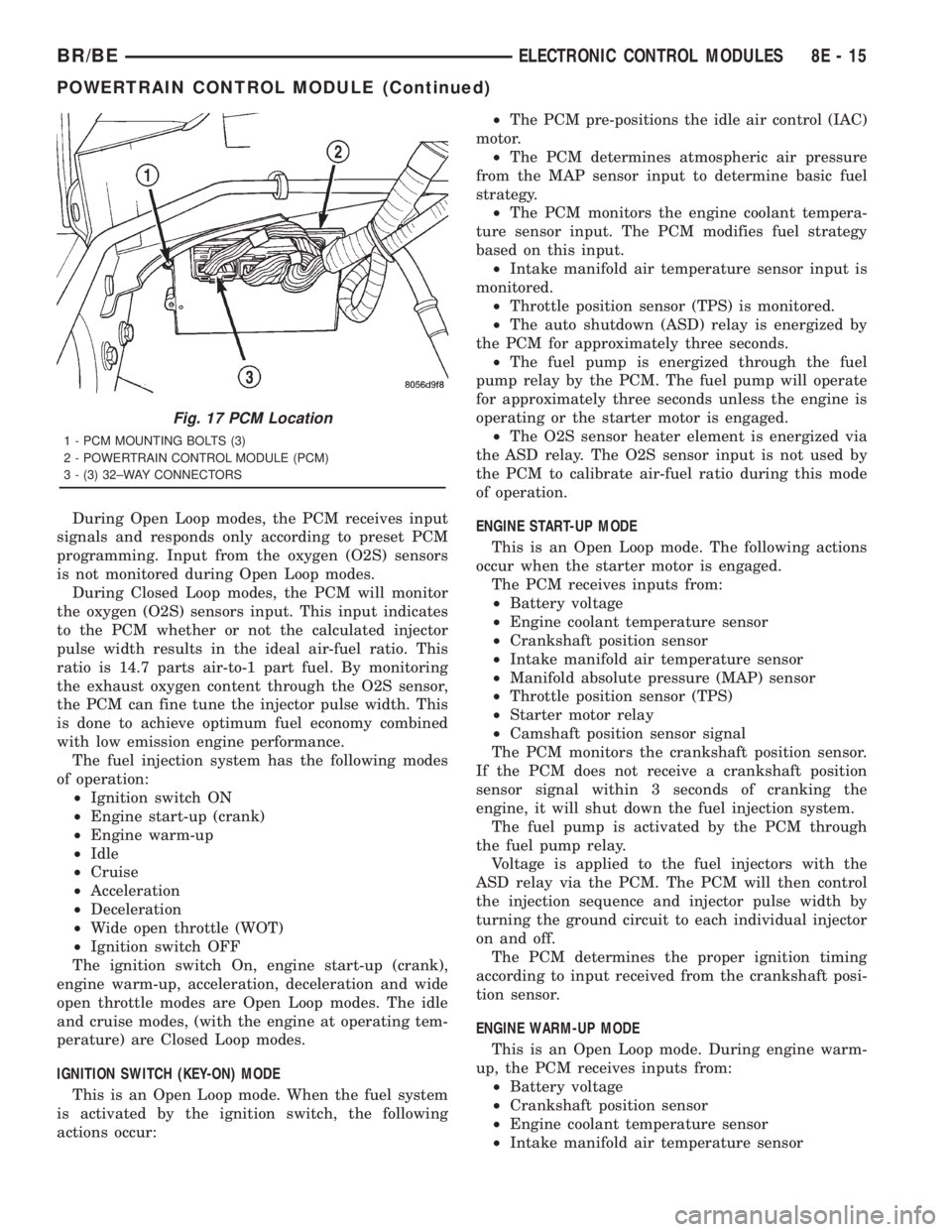
Fig. 17 PCM Location
1 - PCM MOUNTING BOLTS (3)
2 - POWERTRAIN CONTROL MODULE (PCM)
3 - (3) 32±WAY CONNECTORS
BR/BEELECTRONIC CONTROL MODULES 8E - 15
POWERTRAIN CONTROL MODULE (Continued)
Page 470 of 2889
²Power ground
²Sensor return
²Signal ground
²Speed control resume switch
²Speed control set switch
²Speed control on/off switch
²Transmission governor pressure sensor
²Transmission temperature sensor
²Vehicle speed inputs from ABS or RWAL system
NOTE: PCM Outputs:
After inputs are received by the PCM, certain sen-
sors, switches and components are controlled or reg-
ulated by the PCM. These are consideredPCM
Outputs.These outputs are for:
²A/C clutch relay and A/C clutch
²Auto shutdown (ASD) relay
²CCD bus (+/-) circuits for: speedometer, voltme-
ter, fuel gauge, oil pressure gauge/lamp, engine temp.
gauge and speed control warn. lamp
²Data link connection for DRB scan tool
²Five volt sensor supply
²Generator field driver (-)
²Generator field driver (+)
²Generator lamp (if equipped)
²Malfunction indicator lamp (Check engine lamp)
²Overdrive warning lamp (if equipped)
²Speed control vacuum solenoid
²Speed control vent solenoid
²Tachometer (if equipped)
²Transmission convertor clutch circuit
²Transmission 3±4 shift solenoid
²Transmission relay
²Transmission temperature lamp (if equipped)
²Transmission variable force solenoid (governor
sol.)
OPERATION - 5 VOLT SUPPLIES
Primary 5±volt supply:
²supplies the required 5 volt power source to the
Crankshaft Position (CKP) sensor.
²supplies the required 5 volt power source to the
Camshaft Position (CMP) sensor.
²supplies a reference voltage for the Manifold
Absolute Pressure (MAP) sensor.
²supplies a reference voltage for the Throttle
Position Sensor (TPS) sensor.
Secondary 5±volt supply:
²supplies the required 5 volt power source to the
oil pressure sensor.
²supplies the required 5 volt power source for the
Vehicle Speed Sensor (VSS) (if equipped).
²supplies the 5 volt power source to the transmis-
sion pressure sensor (if equipped with an RE auto-
matic transmission).
OPERATION - IGNITION CIRCUIT SENSE
The ignition circuit sense input tells the PCM the
ignition switch has energized the ignition circuit.
Battery voltage is also supplied to the PCM
through the ignition switch when the ignition is in
the RUN or START position. This is referred to as
the9ignition sense9circuit and is used to9wake up9
the PCM. Voltage on the ignition input can be as low
as 6 volts and the PCM will still function. Voltage is
supplied to this circuit to power the PCM's 8-volt reg-
ulator and to allow the PCM to perform fuel, ignition
and emissions control functions.
REMOVAL
USE THE DRB SCAN TOOL TO REPROGRAM
THE NEW POWERTRAIN CONTROL MODULE
(PCM) WITH THE VEHICLES ORIGINAL IDEN-
TIFICATION NUMBER (VIN) AND THE VEHI-
CLES ORIGINAL MILEAGE. IF THIS STEP IS
NOT DONE, A DIAGNOSTIC TROUBLE CODE
(DTC) MAY BE SET.
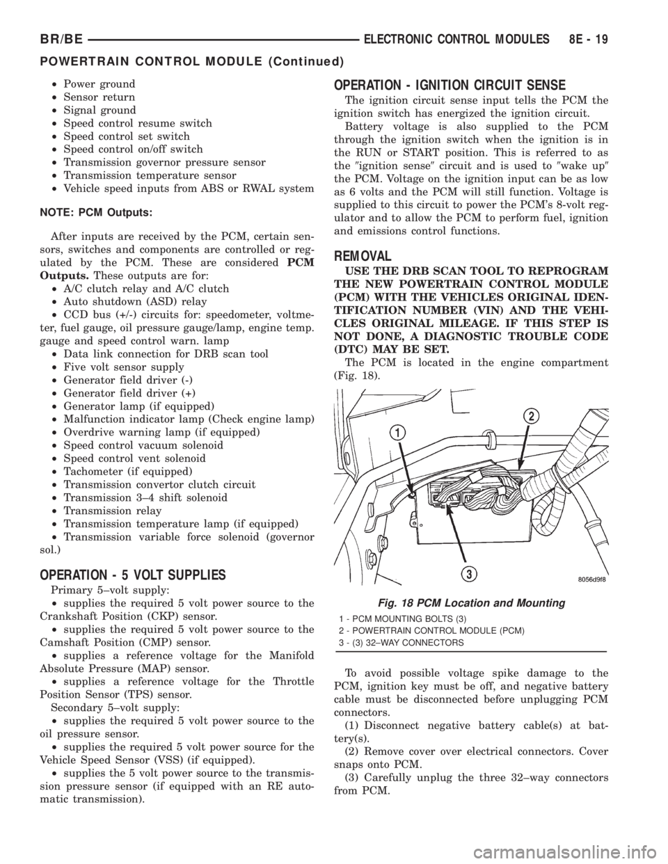
The PCM is located in the engine compartment
(Fig. 18).
To avoid possible voltage spike damage to the
PCM, ignition key must be off, and negative battery
cable must be disconnected before unplugging PCM
connectors.
(1) Disconnect negative battery cable(s) at bat-
tery(s).
(2) Remove cover over electrical connectors. Cover
snaps onto PCM.
(3) Carefully unplug the three 32±way connectors
from PCM.
Fig. 18 PCM Location and Mounting
1 - PCM MOUNTING BOLTS (3)
2 - POWERTRAIN CONTROL MODULE (PCM)
3 - (3) 32±WAY CONNECTORS
BR/BEELECTRONIC CONTROL MODULES 8E - 19
POWERTRAIN CONTROL MODULE (Continued)
Page 495 of 2889
NEGATIVE CABLE INSTALLATION - GASOLINE
(1) Position the battery wire harness into the
engine compartment and under the compressor
mounting bracket, if equipped.
(2) Install and tighten the nut that secures the
battery negative cable ground eyelet terminal to the
stud on the power steering pump pivot bolt.
(3) Install the generator output cable eyelet termi-
nal onto the generator output terminal stud.
(4) Install and tighten the nut that secures the
generator output cable eyelet terminal to the genera-
tor output terminal stud. Tighten the nut to 8.4 N´m
(75 in. lbs.).
(5) Position the cover for the generator output ter-
minal stud housing onto the back of the generator
and snap it into place.
(6) Secure wire assembly in place with pushpin
retainers in there original positions.
(7) Install and tighten the screw that secures the
battery negative cable eyelet terminal to the radiator
closure panel, near the battery. Tighten the screw to
40 in. lbs.
(8) Install and tighten the screw that secures the
battery negative cable eyelet terminal to the left
front side of the frame assembly. Tighten the screw
to 80 in. lbs.
(9) Install and tighten the nut that secures the
battery positive cable eyelet terminal and the gener-
ator output cable eyelet terminal to the PDC B(+)
terminal stud. Tighten the nut to 80 in. lbs.
(10) Reconnect the battery negative cable terminal
clamp to the battery negative terminal post. Tighten
the terminal clamp pinch-bolt hex nut to 35 in. lbs.
(11)
Apply a thin coating of petroleum jelly or chassis
grease to the exposed surfaces of the battery cable ter-
minal clamps and the battery terminal posts.
BATTERY TRAY
DESCRIPTION
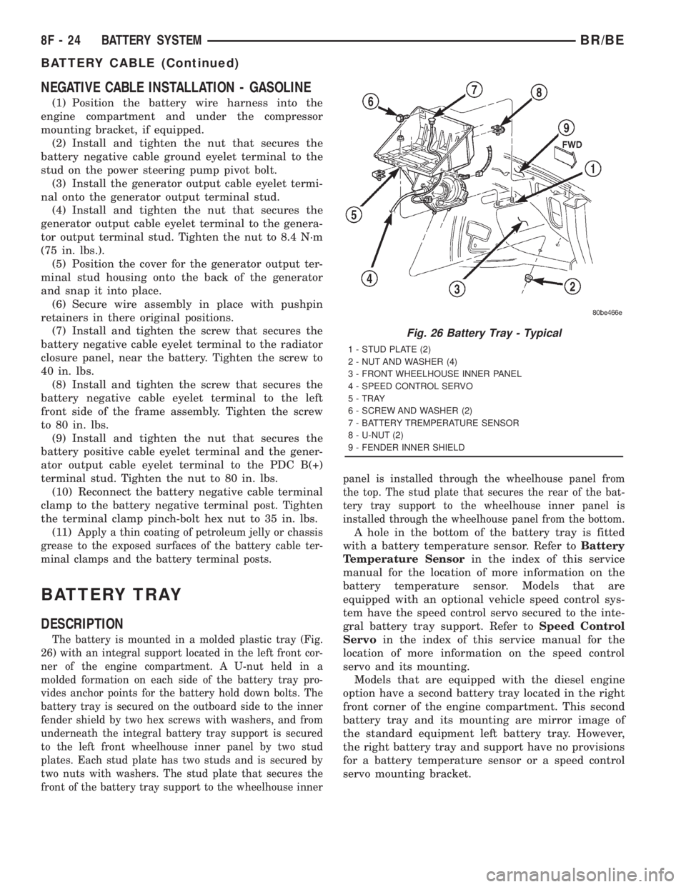
The battery is mounted in a molded plastic tray (Fig.
26) with an integral support located in the left front cor-
ner of the engine compartment. A U-nut held in a
molded formation on each side of the battery tray pro-
vides anchor points for the battery hold down bolts. The
battery tray is secured on the outboard side to the inner
fender shield by two hex screws with washers, and from
underneath the integral battery tray support is secured
to the left front wheelhouse inner panel by two stud
plates. Each stud plate has two studs and is secured by
two nuts with washers. The stud plate that secures the
front of the battery tray support to the wheelhouse innerpanel is installed through the wheelhouse panel from
the top. The stud plate that secures the rear of the bat-
tery tray support to the wheelhouse inner panel is
installed through the wheelhouse panel from the bottom.
A hole in the bottom of the battery tray is fitted
with a battery temperature sensor. Refer toBattery
Temperature Sensorin the index of this service
manual for the location of more information on the
battery temperature sensor. Models that are
equipped with an optional vehicle speed control sys-
tem have the speed control servo secured to the inte-
gral battery tray support. Refer toSpeed Control
Servoin the index of this service manual for the
location of more information on the speed control
servo and its mounting.
Models that are equipped with the diesel engine
option have a second battery tray located in the right
front corner of the engine compartment. This second
battery tray and its mounting are mirror image of
the standard equipment left battery tray. However,
the right battery tray and support have no provisions
for a battery temperature sensor or a speed control
servo mounting bracket.
Fig. 26 Battery Tray - Typical
1 - STUD PLATE (2)
2 - NUT AND WASHER (4)
3 - FRONT WHEELHOUSE INNER PANEL
4 - SPEED CONTROL SERVO
5 - TRAY
6 - SCREW AND WASHER (2)
7 - BATTERY TREMPERATURE SENSOR
8 - U-NUT (2)
9 - FENDER INNER SHIELD
8F - 24 BATTERY SYSTEMBR/BE
BATTERY CABLE (Continued)
Page 496 of 2889
OPERATION
The battery tray provides a secure mounting loca-
tion and supports the battery. On some vehicles, the
battery tray also provides the anchor point/s for the
battery holddown hardware. The battery tray and
the battery holddown hardware combine to secure
and stabilize the battery in the engine compartment,
which prevents battery movement during vehicle
operation. Unrestrained battery movement during
vehicle operation could result in damage to the vehi-
cle, the battery, or both.
REMOVAL
(1) Remove the battery from the battery tray.
Refer toBatteryin this group for the location of the
proper battery removal procedure.
(2) If the left battery tray is being removed,
remove the battery temperature sensor from the left
battery tray. Refer toBattery Temperature Sensor
in the index of this service manual for the location of
the proper battery temperature sensor removal pro-
cedures.
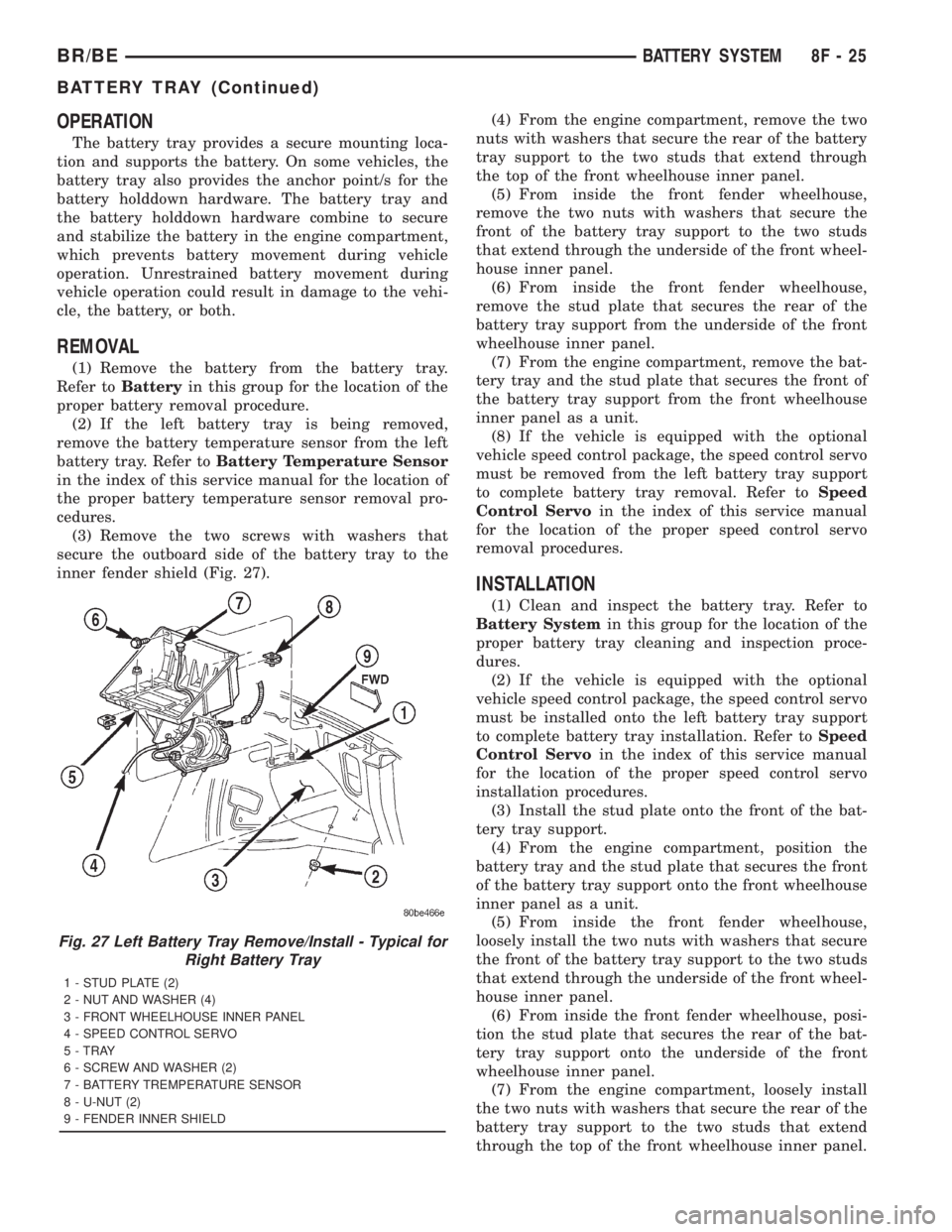
(3) Remove the two screws with washers that
secure the outboard side of the battery tray to the
inner fender shield (Fig. 27).(4) From the engine compartment, remove the two
nuts with washers that secure the rear of the battery
tray support to the two studs that extend through
the top of the front wheelhouse inner panel.
(5) From inside the front fender wheelhouse,
remove the two nuts with washers that secure the
front of the battery tray support to the two studs
that extend through the underside of the front wheel-
house inner panel.
(6) From inside the front fender wheelhouse,
remove the stud plate that secures the rear of the
battery tray support from the underside of the front
wheelhouse inner panel.
(7) From the engine compartment, remove the bat-
tery tray and the stud plate that secures the front of
the battery tray support from the front wheelhouse
inner panel as a unit.
(8) If the vehicle is equipped with the optional
vehicle speed control package, the speed control servo
must be removed from the left battery tray support
to complete battery tray removal. Refer toSpeed
Control Servoin the index of this service manual
for the location of the proper speed control servo
removal procedures.
INSTALLATION
(1) Clean and inspect the battery tray. Refer to
Battery Systemin this group for the location of the
proper battery tray cleaning and inspection proce-
dures.
(2) If the vehicle is equipped with the optional
vehicle speed control package, the speed control servo
must be installed onto the left battery tray support
to complete battery tray installation. Refer toSpeed
Control Servoin the index of this service manual
for the location of the proper speed control servo
installation procedures.
(3) Install the stud plate onto the front of the bat-
tery tray support.
(4) From the engine compartment, position the
battery tray and the stud plate that secures the front
of the battery tray support onto the front wheelhouse
inner panel as a unit.
(5) From inside the front fender wheelhouse,
loosely install the two nuts with washers that secure
the front of the battery tray support to the two studs
that extend through the underside of the front wheel-
house inner panel.
(6) From inside the front fender wheelhouse, posi-
tion the stud plate that secures the rear of the bat-
tery tray support onto the underside of the front
wheelhouse inner panel.
(7) From the engine compartment, loosely install
the two nuts with washers that secure the rear of the
battery tray support to the two studs that extend
through the top of the front wheelhouse inner panel.
Fig. 27 Left Battery Tray Remove/Install - Typical for
Right Battery Tray
1 - STUD PLATE (2)
2 - NUT AND WASHER (4)
3 - FRONT WHEELHOUSE INNER PANEL
4 - SPEED CONTROL SERVO
5 - TRAY
6 - SCREW AND WASHER (2)
7 - BATTERY TREMPERATURE SENSOR
8 - U-NUT (2)
9 - FENDER INNER SHIELD
BR/BEBATTERY SYSTEM 8F - 25
BATTERY TRAY (Continued)
Page 497 of 2889
(8) Install and tighten the two screws with wash-
ers that secure the outboard side of the battery tray
to the inner fender shield. Tighten the screws to 15.8
N´m (140 in. lbs.).
(9) Final tighten the four nuts with washers that
secure the battery tray support to the stud plates on
the front wheelhouse inner panel. Tighten the nuts
to 15.8 N´m (140 in. lbs.).(10) If the left battery tray is being installed,
install the battery temperature sensor onto the left
battery tray. Refer toBattery Temperature Sensor
in the index of this service manual for the location of
the proper battery temperature sensor installation
procedures.
(11) Install the battery onto the battery tray. Refer
toBatteryin this group for the location of the
proper battery installation procedures.
8F - 26 BATTERY SYSTEMBR/BE
BATTERY TRAY (Continued)
Page 500 of 2889
BATTERY TEMPERATURE
SENSOR
DESCRIPTION
The Battery Temperature Sensor (BTS) is attached
to the battery tray located under the battery.
OPERATION
The BTS is used to determine the battery temper-
ature and control battery charging rate. This temper-
ature data, along with data from monitored line
voltage, is used by the PCM to vary the battery
charging rate. System voltage will be higher at colder
temperatures and is gradually reduced at warmer
temperatures.
The PCM sends 5 volts to the sensor and is
grounded through the sensor return line. As temper-
ature increases, resistance in the sensor decreases
and the detection voltage at the PCM increases.
The BTS is also used for OBD II diagnostics. Cer-
tain faults and OBD II monitors are either enabled
or disabled, depending upon BTS input (for example,
disable purge and enable Leak Detection Pump
(LDP) and O2 sensor heater tests). Most OBD II
monitors are disabled below 20ÉF.
REMOVAL
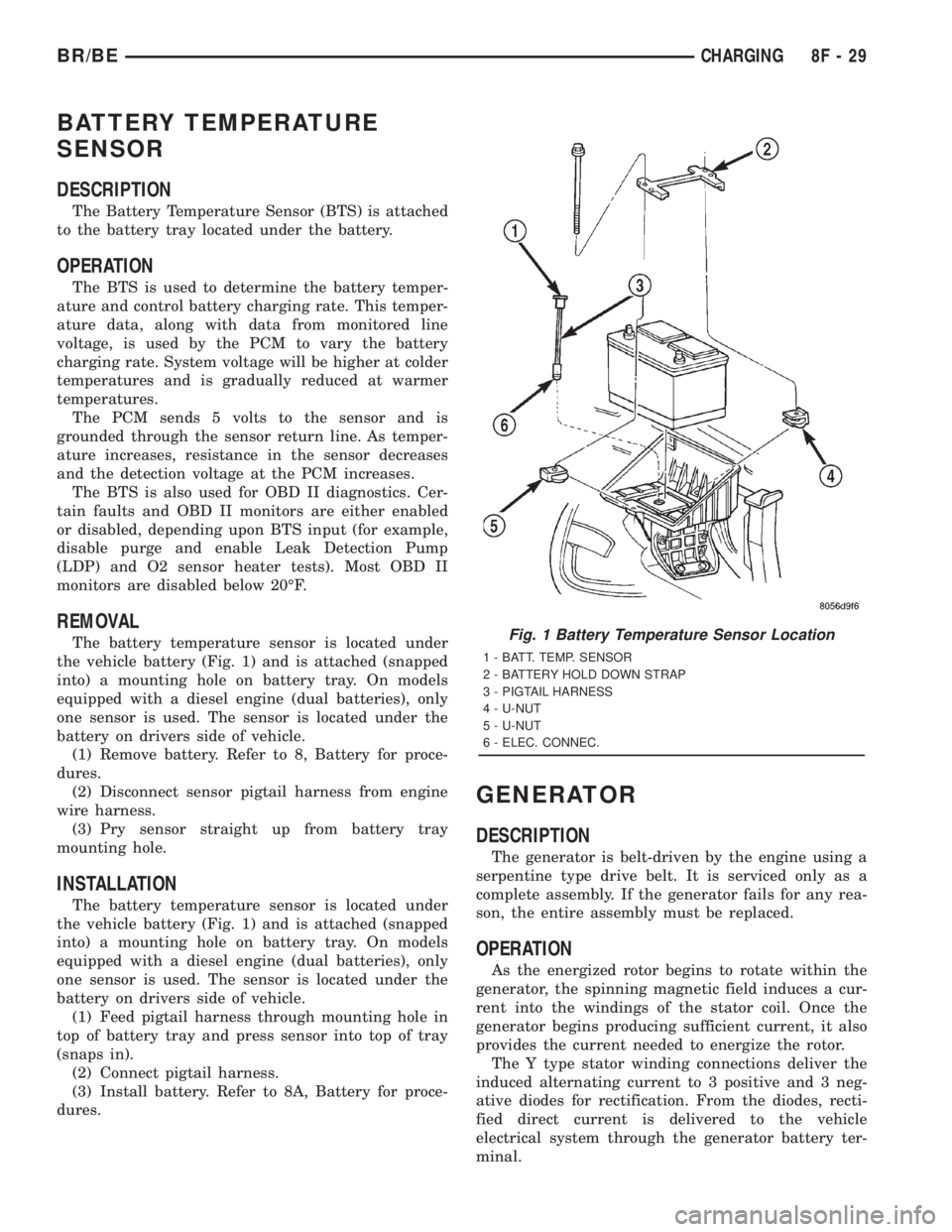
The battery temperature sensor is located under
the vehicle battery (Fig. 1) and is attached (snapped
into) a mounting hole on battery tray. On models
equipped with a diesel engine (dual batteries), only
one sensor is used. The sensor is located under the
battery on drivers side of vehicle.
(1) Remove battery. Refer to 8, Battery for proce-
dures.
(2) Disconnect sensor pigtail harness from engine
wire harness.
(3) Pry sensor straight up from battery tray
mounting hole.
INSTALLATION
The battery temperature sensor is located under
the vehicle battery (Fig. 1) and is attached (snapped
into) a mounting hole on battery tray. On models
equipped with a diesel engine (dual batteries), only
one sensor is used. The sensor is located under the
battery on drivers side of vehicle.
(1) Feed pigtail harness through mounting hole in
top of battery tray and press sensor into top of tray
(snaps in).
(2) Connect pigtail harness.
(3) Install battery. Refer to 8A, Battery for proce-
dures.
GENERATOR
DESCRIPTION
The generator is belt-driven by the engine using a
serpentine type drive belt. It is serviced only as a
complete assembly. If the generator fails for any rea-
son, the entire assembly must be replaced.
OPERATION
As the energized rotor begins to rotate within the
generator, the spinning magnetic field induces a cur-
rent into the windings of the stator coil. Once the
generator begins producing sufficient current, it also
provides the current needed to energize the rotor.
The Y type stator winding connections deliver the
induced alternating current to 3 positive and 3 neg-
ative diodes for rectification. From the diodes, recti-
fied direct current is delivered to the vehicle
electrical system through the generator battery ter-
minal.
Fig. 1 Battery Temperature Sensor Location
1 - BATT. TEMP. SENSOR
2 - BATTERY HOLD DOWN STRAP
3 - PIGTAIL HARNESS
4 - U-NUT
5 - U-NUT
6 - ELEC. CONNEC.
BR/BECHARGING 8F - 29
Page 521 of 2889
OPERATION
The heated seat module receives fused battery cur-
rent through the energized heated seat relay in the
Junction Block (JB) only when the engine is running.
The heated seat switches receive battery current
through a fused ignition switch output (run) circuit
only when the ignition switch is in the On position.
The heated seat module shares a common ground cir-
cuit with each of the heated seat elements. The
heated seat elements will only operate when the sur-
face temperature of the seat cushion cover at the
heated seat sensors is below the designed tempera-
ture set points of the system.
The heated seat module will automatically turn off
the heated seat elements if it detects a short in the
heated seat element circuit or a heated seat sensor
value that is out of range. The heated seat system
will also be turned off automatically whenever the
ignition switch is turned to any position except On or
if the engine quits running. If the ignition switch is
turned to the Off position or if the engine quits run-
ning while a heated seat is turned ON, the heated
seat will remain Off after the engine is restarted
until a heated seat switch is depressed again.
The heated seat module monitors inputs from the
heated seat sensors and the heated seat switches. In
response to these inputs the heated seat module uses
its internal programming to control outputs to the
heated seat elements in both front seats and to con-
trol the heated seat LED indicator lamps located in
both of the heated seat switches. The heated seat
module is also programmed to provide a self-diagnos-
tic capability. When the module detects certain fail-
ures within the heated seat system, it will provide a
visual indication of the failure by flashing the indica-
tor lamps in the heated seat switches.
DIAGNOSIS & TESTING - HEATED SEAT
SYSTEM
SELF-DIAGNOSIS
The heated seat system is capable of performing
some self-diagnostics. The following table depicts the
various failure modes which will be reported to the
vehicle operator or technician by flashing the individ-
ual heated seat switch Light Emitting Diode (LED)
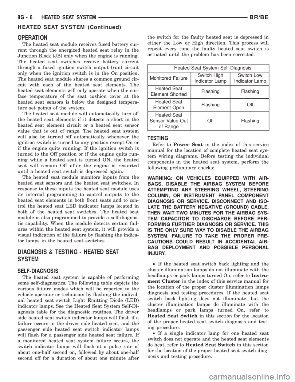
indicator lamps. See the Heated Seat System Self-Di-
agnosis table for the diagnostic routines. The driver
side heated seat switch indicator lamps will flash if a
failure occurs in the driver side heated seat, and the
passenger side heated seat switch indicator lamps
will flash for a passenger side heated seat failure. If
a monitored heated seat system failure occurs, the
switch indicator lamps will flash at a pulse rate of
about one-half second on, followed by about one-half
second off for a duration of about one minute afterthe switch for the faulty heated seat is depressed in
either the Low or High direction. This process will
repeat every time the faulty heated seat switch is
actuated until the problem has been corrected.
Heated Seat System Self-Diagnosis
Monitored FailureSwitch High
Indicator LampSwitch Low
Indicator Lamp
Heated Seat
Element ShortedFlashing Flashing
Heated Seat
Element OpenFlashing Off
Heated Seat
Sensor Value Out
of RangeOff Flashing
TESTING
Refer toPower Seatin the index of this service
manual for the location of complete heated seat sys-
tem wiring diagrams. Before testing the individual
components in the heated seat system, perform the
following preliminary checks:
WARNING: ON VEHICLES EQUIPPED WITH AIR-
BAGS, DISABLE THE AIRBAG SYSTEM BEFORE
ATTEMPTING ANY STEERING WHEEL, STEERING
COLUMN, OR INSTRUMENT PANEL COMPONENT
DIAGNOSIS OR SERVICE. DISCONNECT AND ISO-
LATE THE BATTERY NEGATIVE (GROUND) CABLE,
THEN WAIT TWO MINUTES FOR THE AIRBAG SYS-
TEM CAPACITOR TO DISCHARGE BEFORE PER-
FORMING FURTHER DIAGNOSIS OR SERVICE. THIS
IS THE ONLY SURE WAY TO DISABLE THE AIRBAG
SYSTEM. FAILURE TO TAKE THE PROPER PRE-
CAUTIONS COULD RESULT IN ACCIDENTAL AIR-
BAG DEPLOYMENT AND POSSIBLE PERSONAL
INJURY.
²If the heated seat switch back lighting and the
cluster illumination lamps do not illuminate with the
headlamps or park lamps turned On, refer toInstru-
ment Clusterin the index of this service manual for
the location of the proper cluster illumination lamps
diagnosis and testing procedures. If the heated seat
switch back lighting does not illuminate, but the
cluster illumination lamps do illuminate with the
headlamps or park lamps turned On, refer to
Heated Seat Switchin this section for the location
of the proper heated seat switch diagnosis and test-
ing procedure.
²If a single indicator lamp for one heated seat
switch does not operate and the heated seat elements
do heat, refer toHeated Seat Switchin this section
for the location of the proper heated seat switch diag-
nosis and testing procedure.
8G - 6 HEATED SEAT SYSTEMBR/BE
HEATED SEAT SYSTEM (Continued)
Page 525 of 2889
(3) Reconnect the two instrument panel wire har-
ness connectors to the connector receptacles on the
backs of the heated seat switches.
(4) Position the heated seat switch bezel and both
switches in the instrument panel mounting hole as a
unit.
(5) Install and tighten the three screws that secure
the heated seat switch bezel to the instrument panel.
Tighten the screws to 2.2 N´m (20 in. lbs.).
(6) Install the cluster bezel onto the instrument
panel. Refer toCluster Bezelin the index of this
service manual for the location of the proper cluster
bezel installation procedures.
(7) Reconnect the battery negative cable.
HEATED SEAT ELEMENT
DESCRIPTION
Vehicles equipped with the optional heated seat
system have two sets of electrically operated heating
element grids located in each outboard seating posi-
tion of the front seat, one set for the seat cushion
and the other set for the seat back. Each of the
heated seat element grids consists of a single length
of resistor wire that is routed in a zigzag pattern and
captured between the leather trim cover and the
foam rubber backing on the underside of its respec-
tive seat cushion trim cover and seat back trim cover
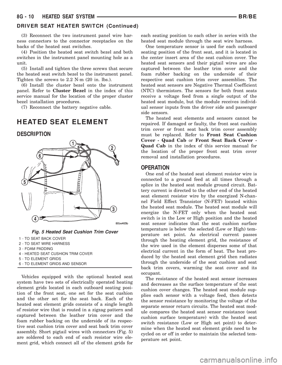
assembly. Short pigtail wires with connectors (Fig. 5)
are soldered to each end of each resistor wire ele-
ment grid, which connect all of the element grids foreach seating position to each other in series with the
heated seat module through the seat wire harness.
One temperature sensor is used for each outboard
seating position of the front seat, and it is located in
the center insert area of the seat cushion cover. The
heated seat sensors and their pigtail wires are also
captured between the leather trim cover and the
foam rubber backing on the underside of their
respective seat cushion trim cover assemblies. The
heated seat sensors are Negative Thermal Coefficient
(NTC) thermistors. The sensors for both front seats
receive a voltage feed from a single output of the
heated seat module, but the module receives individ-
ual sensor inputs from the driver side and passenger
side sensors.
The heated seat elements and sensors cannot be
repaired. If damaged or faulty, the front seat cushion
trim cover or front seat back trim cover assembly
must be replaced. Refer toFront Seat Cushion
Cover - Quad CaborFront Seat Back Cover -
Quad Cabin the index of this service manual for
the location of the proper front seat trim cover
removal and installation procedures.
OPERATION
One end of the heated seat element resistor wire is
connected to a ground feed at all times through a
splice in the heated seat module ground circuit. Bat-
tery current is directed to the other end of the heated
seat element resistor wire by the energized N-chan-
nel Field Effect Transistor (N-FET) located within
the heated seat module. The heated seat module will
energize the N-FET only when the heated seat
switch is in the Low or High position and the heated
seat sensor indicates that the seat cushion surface
temperature is below the selected (Low or High) tem-
perature set point. As electrical current passes
through the heating element grid, the resistance of
the wire used in the element disperses some of that
electrical current in the form of heat. The heat pro-
duced by the heated seat element grid then radiates
through the underside of the seat cushion and seat
back trim covers, warming the seat cover and its
occupant.
The resistance of the heated seat sensor increases
and decreases as the surface temperature of the seat
cushion cover changes. The heated seat module sup-
plies each sensor with a voltage feed, then detects
the sensor resistance by monitoring the voltage of the
separate sensor return circuits. The heated seat mod-
ule compares the heated seat sensor resistance (seat
cushion surface temperature) with the heated seat
switch resistance (Low or High set point) to deter-
mine when the heated seat element grids need to be
cycled on or off in order to maintain the selected tem-
perature set point.
Fig. 5 Heated Seat Cushion Trim Cover
1 - TO SEAT BACK COVER
2 - TO SEAT WIRE HARNESS
3 - FOAM PADDING
4 - HEATED SEAT CUSHION TRIM COVER
5 - TO ELEMENT GRIDS
6 - TO ELEMENT GRIDS AND SENSOR
8G - 10 HEATED SEAT SYSTEMBR/BE
DRIVER SEAT HEATER SWITCH (Continued)
Page 579 of 2889
swept to several calibration points on the gauge scale
in a prescribed sequence in order to confirm the func-
tionality of the gauge and the cluster control cir-
cuitry.
The PCM continually monitors the engine coolant
temperature sensor to determine the engine operat-
ing temperature. The PCM then sends the proper
engine coolant temperature messages to the instru-
ment cluster. For further diagnosis of the engine cool-
ant temperature gauge or the instrument cluster
circuitry that controls the gauge, (Refer to 8 - ELEC-
TRICAL/INSTRUMENT CLUSTER - DIAGNOSIS
AND TESTING). If the instrument cluster turns on
the check gauges indicator due to a high engine tem-
perature gauge reading, it may indicate that the
engine or the engine cooling system requires service.
For proper diagnosis of the engine coolant tempera-
ture sensor, the PCM, the CCD data bus, or the mes-
sage inputs to the instrument cluster that control the
engine coolant temperature gauge, a DRBIIItscan
tool is required. Refer to the appropriate diagnostic
information.
FUEL GAUGE
DESCRIPTION
A fuel gauge is standard equipment on all instru-
ment clusters. The fuel gauge is located in the lower
right quadrant of the instrument cluster, below the
oil pressure gauge. The fuel gauge consists of a mov-
able gauge needle or pointer controlled by the instru-
ment cluster circuitry and a fixed 90 degree scale on
the cluster overlay that reads left-to-right from E (or
Empty) to F (or Full). An International Control and
Display Symbol icon for ªFuelº is located on the clus-
ter overlay, directly below the highest graduation of
the gauge scale. The text ªFUEL DOORº and an
arrowhead pointed to the left side of the vehicle is
imprinted on the cluster overlay directly below the
fuel gauge to provide the driver with a reminder as
to the location of the fuel filler access. The fuel gauge
graphics are white against a black field except for a
single red graduation at the low end of the gauge
scale, making them clearly visible within the instru-
ment cluster in daylight. When illuminated from
behind by the panel lamps dimmer controlled cluster
illumination lighting with the exterior lamps turned
On, the white graphics appear blue-green and the
red graphics appear red. The orange gauge needle is
internally illuminated. Gauge illumination is pro-
vided by replaceable incandescent bulb and bulb
holder units located on the instrument cluster elec-
tronic circuit board. The fuel gauge is serviced as a
unit with the instrument cluster.
OPERATION
The fuel gauge gives an indication to the vehicle
operator of the level of fuel in the fuel tank. This
gauge is controlled by the instrument cluster circuit
board based upon the cluster programming and elec-
tronic messages received by the cluster from the
Powertrain Control Module (PCM) over the Chrysler
Collision Detection (CCD) data bus. The fuel gauge is
an air core magnetic unit that receives battery cur-
rent on the instrument cluster electronic circuit
board through the fused ignition switch output (st-
run) circuit whenever the ignition switch is in the On
or Start positions. The cluster is programmed to
move the gauge needle back to the low end of the
scale after the ignition switch is turned to the Off
position. The instrument cluster circuitry controls
the gauge needle position and provides the following
features:
²Percent Tank Full Message- Each time the
cluster receives a message from the PCM indicating
the percent tank full, the cluster programming
applies an algorithm to calculate the proper gauge
needle position, then moves the gauge needle to the
proper position on the gauge scale. The algorithm is
used to dampen gauge needle movement against the
negative effect that fuel sloshing within the fuel tank
can have on accurate inputs from the fuel tank send-
ing unit to the PCM.
²Less Than 12.5 Percent Tank Full Message-
Each time the cluster receives messages from the
PCM indicating the percent tank full is 12.5 (one-
eighth) or less for 10 consecutive seconds and the
vehicle speed is zero, or for 60 consecutive seconds
and the vehicle speed is greater than zero, the gauge
needle is moved to the proper position on the gauge
scale, the low fuel indicator is illuminated, and a sin-
gle chime tone is sounded. The low fuel indicator
remains illuminated until the cluster receives mes-
sages from the PCM indicating that the percent tank
full is greater than 12.5 (one-eighth) for 10 consecu-
tive seconds and the vehicle speed is zero, or for 60
consecutive seconds and the vehicle speed is greater
than zero, or until the ignition switch is turned to
the Off position, whichever occurs first. The chime
tone feature will only repeat during the same igni-
tion cycle if the low fuel indicator is cycled off and
then on again by the appropriate percent tank full
messages from the PCM.
²Less Than Empty Percent Tank Full Mes-
sage- Each time the cluster receives a message from
the PCM indicating the percent tank full is less than
empty, the gauge needle is moved to the far left (low)
end of the gauge scale and the low fuel indicator is
illuminated immediately. This message would indi-
cate that the fuel tank sender input to the PCM is a
short circuit.
8J - 20 INSTRUMENT CLUSTERBR/BE
ENGINE TEMPERATURE GAUGE (Continued)