ad blue DODGE RAM 2001 Service Repair Manual
[x] Cancel search | Manufacturer: DODGE, Model Year: 2001, Model line: RAM, Model: DODGE RAM 2001Pages: 2889, PDF Size: 68.07 MB
Page 415 of 2889
WARNING: WEAR PROTECTIVE EYEWEAR THAT
MEETS THE REQUIREMENTS OF OSHA AND ANSI
Z87.1±1968. WEAR STANDARD INDUSTRIAL RUB-
BER GLOVES.
KEEP LIGHTED CIGARETTES, SPARKS, FLAMES,
AND OTHER IGNITION SOURCES AWAY FROM THE
AREA TO PREVENT THE IGNITION OF COMBUSTI-
BLE LIQUIDS AND GASES. KEEP A CLASS (B) FIRE
EXTINGUISHER IN THE AREA WHERE THE
FLUSHER WILL BE USED.
KEEP THE AREA WELL VENTILATED.
DO NOT LET FLUSHING SOLVENT COME IN CON-
TACT WITH YOUR EYES OR SKIN: IF EYE CONTAM-
INATION OCCURS, FLUSH EYES WITH WATER FOR
15 TO 20 SECONDS. REMOVE CONTAMINATED
CLOTHING AND WASH AFFECTED SKIN WITH
SOAP AND WATER. SEEK MEDICAL ATTENTION.
(1) Remove cover plate filler plug on Tool 6906-B.
Fill reservoir 1/2 to 3/4 full of fresh flushing solution.
Flushing solvents are petroleum based solutions gen-
erally used to clean automatic transmission compo-
nents.DO NOTuse solvents containing acids, water,
gasoline, or any other corrosive liquids.
(2) Reinstall filler plug on Tool 6906-B.(3) Verify pump power switch is turned OFF. Con-
nect red alligator clip to positive (+) battery post.
Connect black (-) alligator clip to a good ground.
(4) Disconnect the cooler lines at the transmission.
NOTE: When flushing transmission cooler and
lines, ALWAYS reverse flush.
NOTE: The converter drainback valve must be
removed and an appropriate replacement hose
installed to bridge the space between the transmis-
sion cooler line and the cooler fitting. Failure to
remove the drainback valve will prevent reverse
flushing the system. A suitable replacement hose
can be found in the adapter kit supplied with the
flushing tool.
(5) Connect the BLUE pressure line to the OUT-
LET (From) cooler line.
(6) Connect the CLEAR return line to the INLET
(To) cooler line
(7) Turn pump ON for two to three minutes to
flush cooler(s) and lines.
(8) Turn pump OFF.
(9) Disconnect CLEAR suction line from reservoir
at cover plate. Disconnect CLEAR return line at
cover plate, and place it in a drain pan.
(10) Turn pump ON for 30 seconds to purge flush-
ing solution from cooler and lines. Turn pump OFF.
(11) Place CLEAR suction line into a one quart
container of MopartATF +4, type 9602, Automatic
Transmission Fluid.
(12) Turn pump ON until all transmission fluid is
removed from the one quart container and lines. This
purges any residual cleaning solvent from the trans-
mission cooler and lines. Turn pump OFF.
(13) Disconnect alligator clips from battery. Recon-
nect flusher lines to cover plate, and remove flushing
adapters from cooler lines.
STANDARD PROCEDURE - FLUSHING COOLER
AND TUBES - WITHOUT RADIATOR IN-TANK
TRANSMISSION OIL COOLER
When a transmission failure has contaminated the
fluid, the oil cooler(s) must be flushed. The torque
converter must also be replaced. This will insure that
metal particles or sludged oil are not later trans-
ferred back into the reconditioned (or replaced) trans-
mission.
(1) Remove cover plate filler plug on Tool 6906B.
Fill reservoir 1/2 to 3/4 full of fresh flushing solution.
Flushing solvents are petroleum based solutions gen-
erally used to clean automatic transmission compo-
nents.DO NOTuse solvents containing acids, water,
gasoline, or any other corrosive liquids.
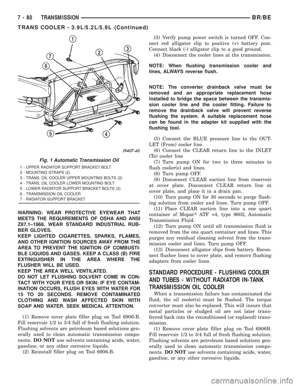
Fig. 1 Automatic Transmission Oil
1 - UPPER RADIATOR SUPPORT BRACKET BOLT
2 - MOUNTING STRAPS (2)
3 - TRANS. OIL COOLER UPPER MOUNTING BOLTS (2)
4 - TRANS. OIL COOLER LOWER MOUNTING BOLT
5 - LOWER RADIATOR SUPPORT BRACKET BOLTS (2)
6 - TRANSMISSION OIL COOLER
7 - RADIATOR SUPPORT BRACKET
7 - 80 TRANSMISSIONBR/BE
TRANS COOLER - 3.9L/5.2L/5.9L (Continued)
Page 416 of 2889
(2) Reinstall filler plug on Tool 6906B.
(3) Verify pump power switch is turned OFF. Con-
nect red alligator clip to positive (+) battery post.
Connect black (-) alligator clip to a good ground.
(4) Disconnect the cooler lines at the transmission.
NOTE: When flushing transmission cooler and
lines, ALWAYS reverse flush.
NOTE: The converter drainback valve must be
removed and an appropriate replacement hose
installed to bridge the space between the transmis-
sion cooler line and the cooler fitting. Failure to
remove the drainback valve will prevent reverse
flushing the system. A suitable replacement hose
can be found in the adapter kit supplied with the
flushing tool.
(5) Connect the BLUE pressure line to the OUT-
LET (From) cooler line.
(6) Connect the CLEAR return line to the INLET
(To) cooler line
(7) Remove the transmission oil cooler from the
vehicle. (Refer to 7 - COOLING/TRANSMISSION/
TRANS COOLER - REMOVAL)
(8) Remove the transmission oil cooler thermostat.
(Refer to 7 - COOLING/TRANSMISSION/TRANS
COOLER - DISASSEMBLY)
(9) Re-install the thermostat cover onto the oil
cooler and install the snap-ring.
(10) Re-connect the oil cooler to the transmission
cooler lines.
(11) Turn pump ON for two to three minutes to
flush cooler(s) and lines.
NOTE: This flushes the bypass circuit of the cooler
only.
(12) Turn pump OFF.
(13) Remove the thermostat cover from the oil
cooler.
(14) Install Special Tool Cooler Plug 8414 into the
transmission oil cooler.
(15) Re-install the thermostat cover onto the oil
cooler and install the snap-ring.
(16) Turn pump ON for two to three minutes to
flush cooler(s) and lines.
NOTE: This flushes the main oil cooler core pas-
sages only.
(17) Turn pump OFF.
(18) Remove the thermostat cover from the oil
cooler.
(19) Remove Special Tool Cooler Plug 8414 from
the transmission oil cooler.(20) Install a new thermostat spring, thermostat,
cover, and snap-ring into the transmission oil cooler.
(Refer to 7 - COOLING/TRANSMISSION/TRANS
COOLER - ASSEMBLY)
(21) Install the transmission oil cooler onto the
vehicle. (Refer to 7 - COOLING/TRANSMISSION/
TRANS COOLER - INSTALLATION)
(22) Disconnect CLEAR suction line from reservoir
at cover plate. Disconnect CLEAR return line at
cover plate, and place it in a drain pan.
(23) Turn pump ON for 30 seconds to purge flush-
ing solution from cooler and lines. Turn pump OFF.
(24) Place CLEAR suction line into a one quart
container of MopartATF +4, type 9602, Automatic
Transmission fluid.
(25) Turn pump ON until all transmission fluid is
removed from the one quart container and lines. This
purges any residual cleaning solvent from the trans-
mission cooler and lines. Turn pump OFF.
(26) Disconnect alligator clips from battery. Recon-
nect flusher lines to cover plate, and remove flushing
adapters from cooler lines.
REMOVAL
(1) Disconnect battery negative cable.
(2) Place a drain pan under the oil cooler lines.
(3) Disconnect the transmission oil cooler line
quick-connect fitting at the cooler outlet using the
quick connect release tool 6935. Loosen clamp from
inlet connection and slide hose off of nipple. Plug
cooler lines to prevent oil leakage.
(4) Remove the oil cooler lower mounting bolt (oil
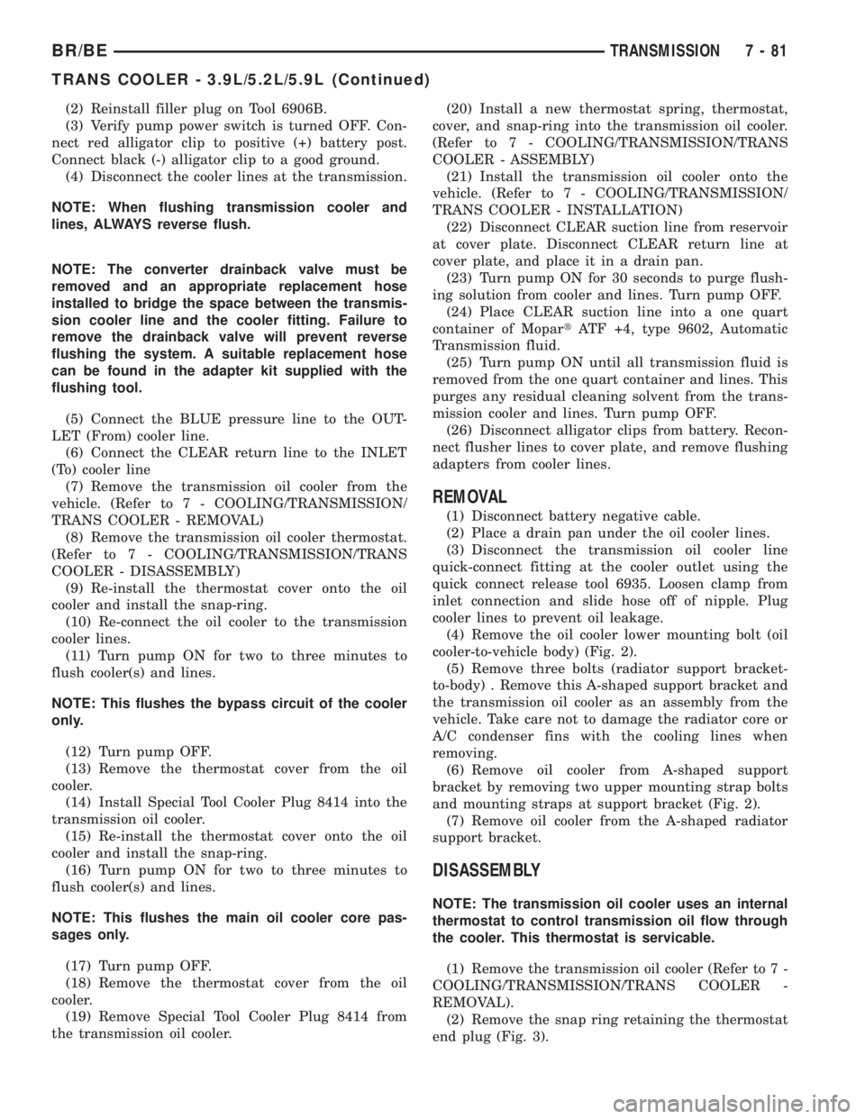
cooler-to-vehicle body) (Fig. 2).
(5) Remove three bolts (radiator support bracket-
to-body) . Remove this A-shaped support bracket and
the transmission oil cooler as an assembly from the
vehicle. Take care not to damage the radiator core or
A/C condenser fins with the cooling lines when
removing.
(6) Remove oil cooler from A-shaped support
bracket by removing two upper mounting strap bolts
and mounting straps at support bracket (Fig. 2).
(7) Remove oil cooler from the A-shaped radiator
support bracket.
DISASSEMBLY
NOTE: The transmission oil cooler uses an internal
thermostat to control transmission oil flow through
the cooler. This thermostat is servicable.
(1) Remove the transmission oil cooler (Refer to 7 -
COOLING/TRANSMISSION/TRANS COOLER -
REMOVAL).
(2) Remove the snap ring retaining the thermostat
end plug (Fig. 3).
BR/BETRANSMISSION 7 - 81
TRANS COOLER - 3.9L/5.2L/5.9L (Continued)
Page 418 of 2889
STANDARD PROCEDURE - FLUSHING
COOLERS AND TUBES - WITH RADIATOR
IN-TANK TRANSMISSION OIL COOLER
When a transmission failure has contaminated the
fluid, the oil cooler(s) must be flushed. The torque
converter must also be replaced. This will insure that
metal particles or sludged oil are not later trans-
ferred back into the reconditioned (or replaced) trans-
mission.
The only recommended procedure for flushing cool-
ers and lines is to use Tool 6906-B Cooler Flusher.
WARNING: WEAR PROTECTIVE EYEWEAR THAT
MEETS THE REQUIREMENTS OF OSHA AND ANSI
Z87.1±1968. WEAR STANDARD INDUSTRIAL RUB-
BER GLOVES.
KEEP LIGHTED CIGARETTES, SPARKS, FLAMES,
AND OTHER IGNITION SOURCES AWAY FROM THE
AREA TO PREVENT THE IGNITION OF COMBUSTI-
BLE LIQUIDS AND GASES. KEEP A CLASS (B) FIRE
EXTINGUISHER IN THE AREA WHERE THE
FLUSHER WILL BE USED.
KEEP THE AREA WELL VENTILATED.
DO NOT LET FLUSHING SOLVENT COME IN CON-
TACT WITH YOUR EYES OR SKIN: IF EYE CONTAM-
INATION OCCURS, FLUSH EYES WITH WATER FOR
15 TO 20 SECONDS. REMOVE CONTAMINATED
CLOTHING AND WASH AFFECTED SKIN WITH
SOAP AND WATER. SEEK MEDICAL ATTENTION.
(1) Remove cover plate filler plug on Tool 6906-B.
Fill reservoir 1/2 to 3/4 full of fresh flushing solution.
Flushing solvents are petroleum based solutions gen-
erally used to clean automatic transmission compo-
nents.DO NOTuse solvents containing acids, water,
gasoline, or any other corrosive liquids.(2) Reinstall filler plug on Tool 6906-B.
(3) Verify pump power switch is turned OFF. Con-
nect red alligator clip to positive (+) battery post.
Connect black (-) alligator clip to a good ground.
(4) Disconnect the cooler lines at the transmission.
NOTE: When flushing transmission cooler and
lines, ALWAYS reverse flush.
NOTE: The converter drainback valve must be
removed and an appropriate replacement hose
installed to bridge the space between the transmis-
sion cooler line and the cooler fitting. Failure to
remove the drainback valve will prevent reverse
flushing the system. A suitable replacement hose
can be found in the adapter kit supplied with the
flushing tool.
(5) Connect the BLUE pressure line to the OUT-
LET (From) cooler line.
(6) Connect the CLEAR return line to the INLET
(To) cooler line
(7) Turn pump ON for two to three minutes to
flush cooler(s) and lines.
(8) Turn pump OFF.
(9) Disconnect CLEAR suction line from reservoir
at cover plate. Disconnect CLEAR return line at
cover plate, and place it in a drain pan.
(10) Turn pump ON for 30 seconds to purge flush-
ing solution from cooler and lines. Turn pump OFF.
(11) Place CLEAR suction line into a one quart
container of MopartATF +4, type 9602, Automatic
Transmission Fluid.
(12) Turn pump ON until all transmission fluid is
removed from the one quart container and lines. This
purges any residual cleaning solvent from the trans-
mission cooler and lines. Turn pump OFF.
(13) Disconnect alligator clips from battery. Recon-
nect flusher lines to cover plate, and remove flushing
adapters from cooler lines.
STANDARD PROCEDURE - FLUSHING COOLER
AND TUBES - WITHOUT RADIATOR IN-TANK
TRANSMISSION OIL COOLER
When a transmission failure has contaminated the
fluid, the oil cooler(s) must be flushed. The torque
converter must also be replaced. This will insure that
metal particles or sludged oil are not later trans-
ferred back into the reconditioned (or replaced) trans-
mission.
(1) Remove cover plate filler plug on Tool 6906B.
Fill reservoir 1/2 to 3/4 full of fresh flushing solution.
Flushing solvents are petroleum based solutions gen-
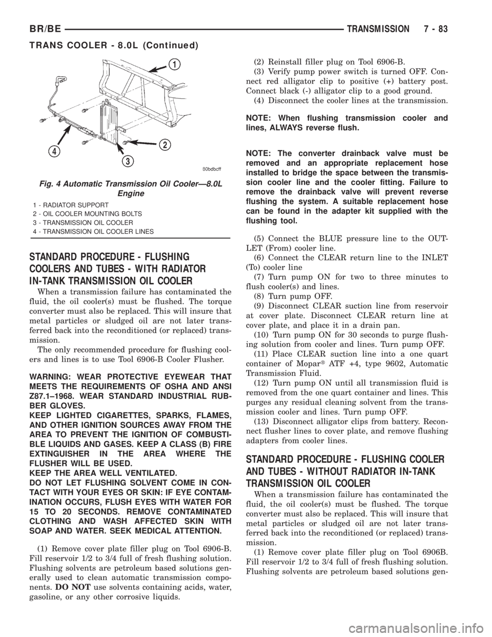
Fig. 4 Automatic Transmission Oil CoolerÐ8.0L
Engine
1 - RADIATOR SUPPORT
2 - OIL COOLER MOUNTING BOLTS
3 - TRANSMISSION OIL COOLER
4 - TRANSMISSION OIL COOLER LINES
BR/BETRANSMISSION 7 - 83
TRANS COOLER - 8.0L (Continued)
Page 419 of 2889
erally used to clean automatic transmission compo-
nents.DO NOTuse solvents containing acids, water,
gasoline, or any other corrosive liquids.
(2) Reinstall filler plug on Tool 6906B.
(3) Verify pump power switch is turned OFF. Con-
nect red alligator clip to positive (+) battery post.
Connect black (-) alligator clip to a good ground.
(4) Disconnect the cooler lines at the transmission.
NOTE: When flushing transmission cooler and
lines, ALWAYS reverse flush.
NOTE: The converter drainback valve must be
removed and an appropriate replacement hose
installed to bridge the space between the transmis-
sion cooler line and the cooler fitting. Failure to
remove the drainback valve will prevent reverse
flushing the system. A suitable replacement hose
can be found in the adapter kit supplied with the
flushing tool.
(5) Connect the BLUE pressure line to the OUT-
LET (From) cooler line.
(6) Connect the CLEAR return line to the INLET
(To) cooler line
(7) Remove the transmission oil cooler from the
vehicle. (Refer to 7 - COOLING/TRANSMISSION/
TRANS COOLER - REMOVAL)
(8) Remove the transmission oil cooler thermostat.
(Refer to 7 - COOLING/TRANSMISSION/TRANS
COOLER - DISASSEMBLY)
(9) Re-install the thermostat cover onto the oil
cooler and install the snap-ring.
(10) Re-connect the oil cooler to the transmission
cooler lines.
(11) Turn pump ON for two to three minutes to
flush cooler(s) and lines.
NOTE: This flushes the bypass circuit of the cooler
only.
(12) Turn pump OFF.
(13) Remove the thermostat cover from the oil
cooler.
(14) Install Special Tool Cooler Plug 8414 into the
transmission oil cooler.
(15) Re-install the thermostat cover onto the oil
cooler and install the snap-ring.
(16) Turn pump ON for two to three minutes to
flush cooler(s) and lines.
NOTE: This flushes the main oil cooler core pas-
sages only.
(17) Turn pump OFF.
(18) Remove the thermostat cover from the oil
cooler.(19) Remove Special Tool Cooler Plug 8414 from
the transmission oil cooler.
(20) Install a new thermostat spring, thermostat,
cover, and snap-ring into the transmission oil cooler.
(Refer to 7 - COOLING/TRANSMISSION/TRANS
COOLER - ASSEMBLY)
(21) Install the transmission oil cooler onto the
vehicle. (Refer to 7 - COOLING/TRANSMISSION/
TRANS COOLER - INSTALLATION)
(22) Disconnect CLEAR suction line from reservoir
at cover plate. Disconnect CLEAR return line at
cover plate, and place it in a drain pan.
(23) Turn pump ON for 30 seconds to purge flush-
ing solution from cooler and lines. Turn pump OFF.
(24) Place CLEAR suction line into a one quart
container of MopartATF +4, type 9602, Automatic
Transmission fluid.
(25) Turn pump ON until all transmission fluid is
removed from the one quart container and lines. This
purges any residual cleaning solvent from the trans-
mission cooler and lines. Turn pump OFF.
(26) Disconnect alligator clips from battery. Recon-
nect flusher lines to cover plate, and remove flushing
adapters from cooler lines.
REMOVAL
(1) Place a drain pan under the oil cooler lines.
(2) Disconnect the two transmission lines from the
oil cooler by loosening the two worm gear clamps and
pulling the rubber hoses off of the oil cooler tubes
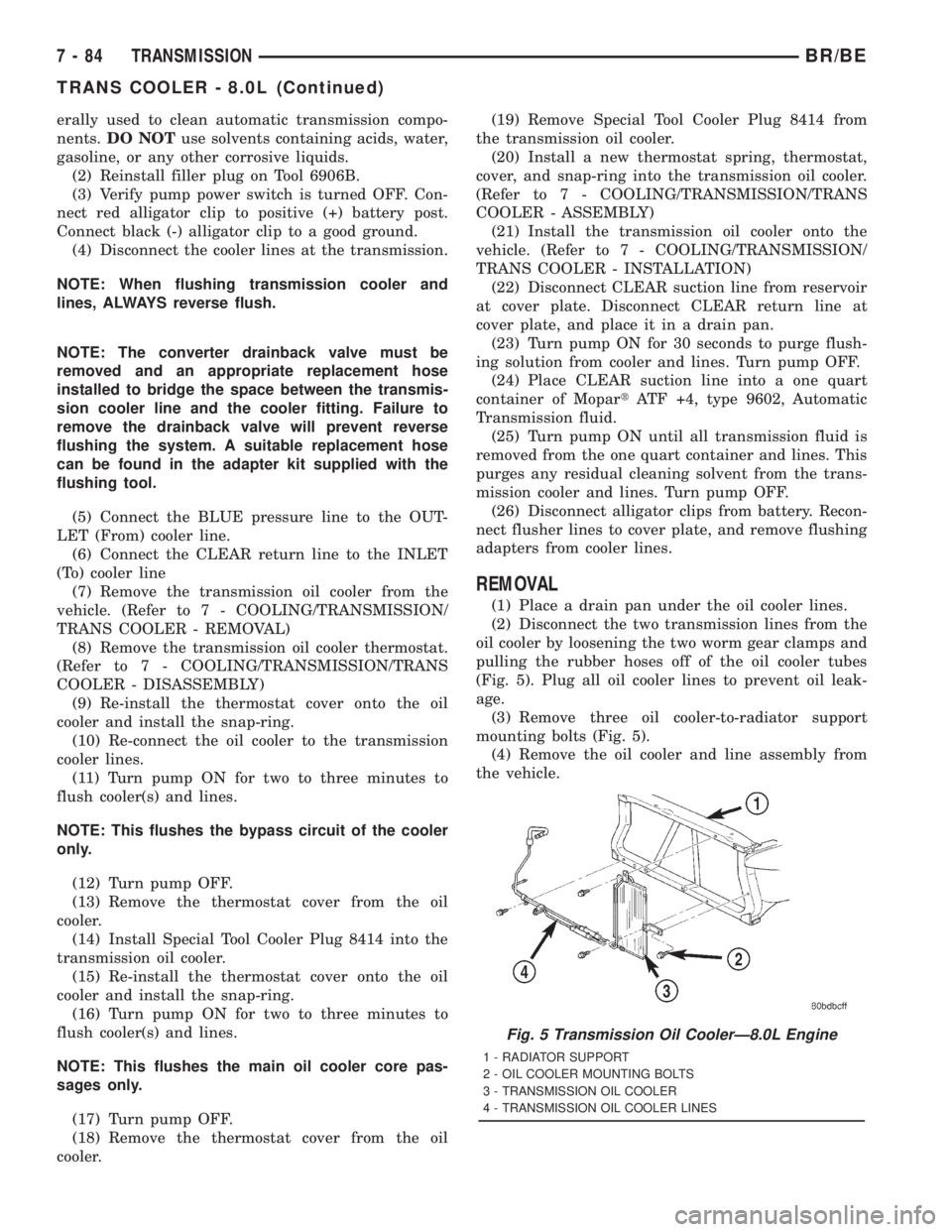
(Fig. 5). Plug all oil cooler lines to prevent oil leak-
age.
(3) Remove three oil cooler-to-radiator support
mounting bolts (Fig. 5).
(4) Remove the oil cooler and line assembly from
the vehicle.
Fig. 5 Transmission Oil CoolerÐ8.0L Engine
1 - RADIATOR SUPPORT
2 - OIL COOLER MOUNTING BOLTS
3 - TRANSMISSION OIL COOLER
4 - TRANSMISSION OIL COOLER LINES
7 - 84 TRANSMISSIONBR/BE
TRANS COOLER - 8.0L (Continued)
Page 421 of 2889
WARNING: WEAR PROTECTIVE EYEWEAR THAT
MEETS THE REQUIREMENTS OF OSHA AND ANSI
Z87.1±1968. WEAR STANDARD INDUSTRIAL RUB-
BER GLOVES.
KEEP LIGHTED CIGARETTES, SPARKS, FLAMES,
AND OTHER IGNITION SOURCES AWAY FROM THE
AREA TO PREVENT THE IGNITION OF COMBUSTI-
BLE LIQUIDS AND GASES. KEEP A CLASS (B) FIRE
EXTINGUISHER IN THE AREA WHERE THE
FLUSHER WILL BE USED.
KEEP THE AREA WELL VENTILATED.
DO NOT LET FLUSHING SOLVENT COME IN CON-
TACT WITH YOUR EYES OR SKIN: IF EYE CONTAM-
INATION OCCURS, FLUSH EYES WITH WATER FOR
15 TO 20 SECONDS. REMOVE CONTAMINATED
CLOTHING AND WASH AFFECTED SKIN WITH
SOAP AND WATER. SEEK MEDICAL ATTENTION.
(1) Remove cover plate filler plug on Tool 6906-B.
Fill reservoir 1/2 to 3/4 full of fresh flushing solution.
Flushing solvents are petroleum based solutions gen-
erally used to clean automatic transmission compo-
nents.DO NOTuse solvents containing acids, water,
gasoline, or any other corrosive liquids.
(2) Reinstall filler plug on Tool 6906-B.
(3) Verify pump power switch is turned OFF. Con-
nect red alligator clip to positive (+) battery post.
Connect black (-) alligator clip to a good ground.
(4) Disconnect the cooler lines at the transmission.
NOTE: When flushing transmission cooler and
lines, ALWAYS reverse flush.
NOTE: The converter drainback valve must be
removed and an appropriate replacement hose
installed to bridge the space between the transmis-
sion cooler line and the cooler fitting. Failure to
remove the drainback valve will prevent reverse
flushing the system. A suitable replacement hose
can be found in the adapter kit supplied with the
flushing tool.
(5) Connect the BLUE pressure line to the OUT-
LET (From) cooler line.
(6) Connect the CLEAR return line to the INLET
(To) cooler line
(7) Turn pump ON for two to three minutes to
flush cooler(s) and lines.
(8) Turn pump OFF.
(9) Disconnect CLEAR suction line from reservoir
at cover plate. Disconnect CLEAR return line at
cover plate, and place it in a drain pan.
(10) Turn pump ON for 30 seconds to purge flush-
ing solution from cooler and lines. Turn pump OFF.(11) Place CLEAR suction line into a one quart
container of MopartATF +4, type 9602, Automatic
Transmission Fluid.
(12) Turn pump ON until all transmission fluid is
removed from the one quart container and lines. This
purges any residual cleaning solvent from the trans-
mission cooler and lines. Turn pump OFF.
(13) Disconnect alligator clips from battery. Recon-
nect flusher lines to cover plate, and remove flushing
adapters from cooler lines.
STANDARD PROCEDURE - FLUSHING COOLER
AND TUBES - WITHOUT RADIATOR IN-TANK
TRANSMISSION OIL COOLER
When a transmission failure has contaminated the
fluid, the oil cooler(s) must be flushed. The torque
converter must also be replaced. This will insure that
metal particles or sludged oil are not later trans-
ferred back into the reconditioned (or replaced) trans-
mission.
(1) Remove cover plate filler plug on Tool 6906B.
Fill reservoir 1/2 to 3/4 full of fresh flushing solution.
Flushing solvents are petroleum based solutions gen-
erally used to clean automatic transmission compo-
nents.DO NOTuse solvents containing acids, water,
gasoline, or any other corrosive liquids.
(2) Reinstall filler plug on Tool 6906B.
(3) Verify pump power switch is turned OFF. Con-
nect red alligator clip to positive (+) battery post.
Connect black (-) alligator clip to a good ground.
(4) Disconnect the cooler lines at the transmission.
NOTE: When flushing transmission cooler and
lines, ALWAYS reverse flush.
NOTE: The converter drainback valve must be
removed and an appropriate replacement hose
installed to bridge the space between the transmis-
sion cooler line and the cooler fitting. Failure to
remove the drainback valve will prevent reverse
flushing the system. A suitable replacement hose
can be found in the adapter kit supplied with the
flushing tool.
(5) Connect the BLUE pressure line to the OUT-
LET (From) cooler line.
(6) Connect the CLEAR return line to the INLET
(To) cooler line
(7) Remove the transmission oil cooler from the
vehicle. (Refer to 7 - COOLING/TRANSMISSION/
TRANS COOLER - REMOVAL)
(8) Remove the transmission oil cooler thermostat.
(Refer to 7 - COOLING/TRANSMISSION/TRANS
COOLER - DISASSEMBLY)
7 - 86 TRANSMISSIONBR/BE
TRANS COOLER - 5.9L DIESEL (Continued)
Page 561 of 2889
INSTRUMENT CLUSTER
DESCRIPTION
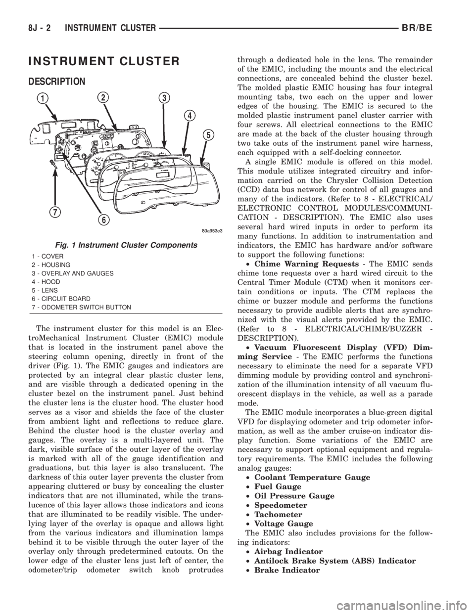
The instrument cluster for this model is an Elec-
troMechanical Instrument Cluster (EMIC) module
that is located in the instrument panel above the
steering column opening, directly in front of the
driver (Fig. 1). The EMIC gauges and indicators are
protected by an integral clear plastic cluster lens,
and are visible through a dedicated opening in the
cluster bezel on the instrument panel. Just behind
the cluster lens is the cluster hood. The cluster hood
serves as a visor and shields the face of the cluster
from ambient light and reflections to reduce glare.
Behind the cluster hood is the cluster overlay and
gauges. The overlay is a multi-layered unit. The
dark, visible surface of the outer layer of the overlay
is marked with all of the gauge identification and
graduations, but this layer is also translucent. The
darkness of this outer layer prevents the cluster from
appearing cluttered or busy by concealing the cluster
indicators that are not illuminated, while the trans-
lucence of this layer allows those indicators and icons
that are illuminated to be readily visible. The under-
lying layer of the overlay is opaque and allows light
from the various indicators and illumination lamps
behind it to be visible through the outer layer of the
overlay only through predetermined cutouts. On the
lower edge of the cluster lens just left of center, the
odometer/trip odometer switch knob protrudesthrough a dedicated hole in the lens. The remainder
of the EMIC, including the mounts and the electrical
connections, are concealed behind the cluster bezel.
The molded plastic EMIC housing has four integral
mounting tabs, two each on the upper and lower
edges of the housing. The EMIC is secured to the
molded plastic instrument panel cluster carrier with
four screws. All electrical connections to the EMIC
are made at the back of the cluster housing through
two take outs of the instrument panel wire harness,
each equipped with a self-docking connector.
A single EMIC module is offered on this model.
This module utilizes integrated circuitry and infor-
mation carried on the Chrysler Collision Detection
(CCD) data bus network for control of all gauges and
many of the indicators. (Refer to 8 - ELECTRICAL/
ELECTRONIC CONTROL MODULES/COMMUNI-
CATION - DESCRIPTION). The EMIC also uses
several hard wired inputs in order to perform its
many functions. In addition to instrumentation and
indicators, the EMIC has hardware and/or software
to support the following functions:
²Chime Warning Requests- The EMIC sends
chime tone requests over a hard wired circuit to the
Central Timer Module (CTM) when it monitors cer-
tain conditions or inputs. The CTM replaces the
chime or buzzer module and performs the functions
necessary to provide audible alerts that are synchro-
nized with the visual alerts provided by the EMIC.
(Refer to 8 - ELECTRICAL/CHIME/BUZZER -
DESCRIPTION).
²Vacuum Fluorescent Display (VFD) Dim-
ming Service- The EMIC performs the functions
necessary to eliminate the need for a separate VFD
dimming module by providing control and synchroni-
zation of the illumination intensity of all vacuum flu-
orescent displays in the vehicle, as well as a parade
mode.
The EMIC module incorporates a blue-green digital
VFD for displaying odometer and trip odometer infor-
mation, as well as the amber cruise-on indicator dis-
play function. Some variations of the EMIC are
necessary to support optional equipment and regula-
tory requirements. The EMIC includes the following
analog gauges:
²Coolant Temperature Gauge
²Fuel Gauge
²Oil Pressure Gauge
²Speedometer
²Tachometer
²Voltage Gauge
The EMIC also includes provisions for the follow-
ing indicators:
²Airbag Indicator
²Antilock Brake System (ABS) Indicator
²Brake Indicator
Fig. 1 Instrument Cluster Components
1 - COVER
2 - HOUSING
3 - OVERLAY AND GAUGES
4 - HOOD
5 - LENS
6 - CIRCUIT BOARD
7 - ODOMETER SWITCH BUTTON
8J - 2 INSTRUMENT CLUSTERBR/BE
Page 563 of 2889
The EMIC circuitry operates on battery current
received through a fused B(+) fuse in the Junction
Block (JB) on a non-switched fused B(+) circuit, and
on battery current received through a fused ignition
switch output (st-run) fuse in the JB on a fused igni-
tion switch output (st-run) circuit. This arrangement
allows the EMIC to provide some features regardless
of the ignition switch position, while other features
will operate only with the ignition switch in the Start
or On positions. The EMIC circuitry is grounded
through two separate ground circuits located in one
of the two instrument cluster connectors and take
outs of the instrument panel wire harness. One
ground circuit receives ground through a take out
with an eyelet terminal connector of the instrument
panel wire harness that is secured by a nut to a
ground stud located on the left instrument panel end
bracket, while the other ground circuit receives
ground through a take out with an eyelet terminal
connector of the instrument panel wire harness that
is secured by a nut to a ground stud located on the
back of the instrument panel armature above the
inboard side of the instrument panel steering column
opening.
The EMIC also has a self-diagnostic actuator test
capability, which will test each of the CCD bus mes-
sage-controlled functions of the cluster by lighting
the appropriate indicators and positioning the gauge
needles at several predetermined locations on the
gauge faces in a prescribed sequence. (Refer to 8 -
ELECTRICAL/INSTRUMENT CLUSTER - DIAGNO-
SIS AND TESTING). See the owner's manual in the
vehicle glove box for more information on the fea-
tures, use and operation of the EMIC.
GAUGES
All gauges receive battery current through the
EMIC circuitry when the ignition switch is in the On
or Start positions. With the ignition switch in the Off
position battery current is not supplied to any
gauges, and the EMIC circuitry is programmed to
move all of the gauge needles back to the low end of
their respective scales. Therefore, the gauges do not
accurately indicate any vehicle condition unless the
ignition switch is in the On or Start positions. All of
the EMIC gauges, except the odometer, are air core
magnetic units. Two fixed electromagnetic coils are
located within each gauge. These coils are wrapped
at right angles to each other around a movable per-
manent magnet. The movable magnet is suspended
within the coils on one end of a pivot shaft, while the
gauge needle is attached to the other end of the
shaft. One of the coils has a fixed current flowing
through it to maintain a constant magnetic fieldstrength. Current flow through the second coil
changes, which causes changes in its magnetic field
strength. The current flowing through the second coil
is changed by the EMIC circuitry in response to mes-
sages received over the CCD data bus. The gauge
needle moves as the movable permanent magnet
aligns itself to the changing magnetic fields created
around it by the electromagnets.
The gauges are diagnosed using the EMIC self-di-
agnostic actuator test. (Refer to 8 - ELECTRICAL/
INSTRUMENT CLUSTER - DIAGNOSIS AND
TESTING). Proper testing of the CCD data bus and
the data bus message inputs to the EMIC that con-
trol each gauge require the use of a DRBIIItscan
tool. Refer to the appropriate diagnostic information.
Specific operation details for each gauge may be
found elsewhere in this service manual.
VACUUM-FLUORESCENT DISPLAY
The Vacuum-Fluorescent Display (VFD) module is
soldered to the EMIC circuit board. The display is
active with the ignition switch in the On or Start
positions, and inactive when the ignition switch is in
any other position. The VFD has several display
capabilities including odometer, trip odometer, and
an amber ªCRUISEº indication whenever the
optional speed control system is turned On. The
cruise indicator function of the VFD is automatically
enabled or disabled by the EMIC circuitry based
upon whether the vehicle is equipped with the speed
control option. An odometer/trip odometer switch on
the EMIC circuit board is used to control several of
the display modes. This switch is actuated manually
by depressing the odometer/trip odometer switch
knob that extends through the lower edge of the clus-
ter lens, just right of center. Actuating this switch
momentarily with the ignition switch in the On posi-
tion will toggle the VFD between the odometer and
trip odometer modes. The word ªTRIPº will also
appear in blue-green text when the VFD trip odome-
ter mode is active. Depressing the switch button for
about two seconds while the VFD is in the trip odom-
eter mode will reset the trip odometer value to zero.
Holding this switch depressed while turning the igni-
tion switch from the Off position to the On position
will activate the EMIC self-diagnostic actuator test.
The EMIC will automatically flash the odometer or
trip odometer information on and off if there is a loss
of CCD data bus communication. The VFD will also
display various information used in several diagnos-
tic procedures. Refer to the appropriate diagnostic
information for additional details on this VFD func-
tion.
8J - 4 INSTRUMENT CLUSTERBR/BE
INSTRUMENT CLUSTER (Continued)
Page 578 of 2889
the instrument cluster. For further diagnosis of the
cruise indicator or the instrument cluster circuitry
that controls the indicator, (Refer to 8 - ELECTRI-
CAL/INSTRUMENT CLUSTER - DIAGNOSIS AND
TESTING). For proper diagnosis of the speed control
system, the PCM, the CCD data bus, or the message
inputs to the instrument cluster that control the
cruise indicator, a DRBIIItscan tool is required.
Refer to the appropriate diagnostic information.
ENGINE TEMPERATURE
GAUGE
DESCRIPTION
An engine coolant temperature gauge is standard
equipment on all instrument clusters. The engine
coolant temperature gauge is located in the lower left
quadrant of the instrument cluster, below the voltage
gauge. The engine coolant temperature gauge con-
sists of a movable gauge needle or pointer controlled
by the instrument cluster circuitry and a fixed 90
degree scale on the cluster overlay that reads left-to-
right from 54É C (130É F) to 127É C (260É F) for gas-
oline engines, or from 60É C (140É F) to 116É C (240É
F) for diesel engines. An International Control and
Display Symbol icon for ªEngine Coolant Tempera-
tureº is located on the cluster overlay, directly below
the lowest graduation of the gauge scale. The engine
coolant temperature gauge graphics are white
against a black field except for a single red gradua-
tion at the high end of the gauge scale, making them
clearly visible within the instrument cluster in day-
light. When illuminated from behind by the panel
lamps dimmer controlled cluster illumination lighting
with the exterior lamps turned On, the white graph-
ics appear blue-green and the red graphics appear
red. The orange gauge needle is internally illumi-
nated. Gauge illumination is provided by replaceable
incandescent bulb and bulb holder units located on
the instrument cluster electronic circuit board. The
engine coolant temperature gauge is serviced as a
unit with the instrument cluster.
OPERATION
The engine coolant temperature gauge gives an
indication to the vehicle operator of the engine cool-
ant temperature. This gauge is controlled by the
instrument cluster circuit board based upon the clus-
ter programming and electronic messages received by
the cluster from the Powertrain Control Module
(PCM) over the Chrysler Collision Detection (CCD)
data bus. The engine coolant temperature gauge is
an air core magnetic unit that receives battery cur-
rent on the instrument cluster electronic circuit
board through the fused ignition switch output (st-run) circuit whenever the ignition switch is in the On
or Start positions. The cluster is programmed to
move the gauge needle back to the low end of the
scale after the ignition switch is turned to the Off
position. The instrument cluster circuitry controls
the gauge needle position and provides the following
features:
²Engine Temperature Message- Each time
the cluster receives a message from the PCM indicat-
ing the engine coolant temperature is between the
low end of normal [about 57É C (130É F) for gasoline
engines, or 60É C (140É F) for diesel engines] and the
high end of normal [about 129É C (264É F) for gaso-
line engines, or 116É C (240É F) for diesel engines],
the gauge needle is moved to the actual temperature
position on the gauge scale.
²Engine Temperature Low Message- Each
time the cluster receives a message from the PCM
indicating the engine coolant temperature is below
the low end of normal [about 57É C (130É F) for gas-
oline engines, or 60É C (140É F) for diesel engines],
the gauge needle is held at the lowest increment [57É
C (130É F) for gasoline engines, or 60É C (140É F) for
diesel engines] at the far left end of the gauge scale.
The gauge needle remains at the far left end of the
scale until the cluster receives a message from the
PCM indicating that the engine temperature is above
about 57É C (130É F) for gasoline engines, or 60É C
(140É F) for diesel engines, or until the ignition
switch is turned to the Off position, whichever occurs
first.
²Engine Temperature High Message- Each
time the cluster receives a message from the PCM
indicating the engine coolant temperature is above
about 122É C (253É F) for gasoline engines, or 112É C
(233É F) for diesel engines, the gauge needle is moved
to the appropriate position on the gauge scale, the
check gauges indicator is illuminated, and a single
chime tone is sounded. The check gauges indicator
remains illuminated until the cluster receives a mes-
sage from the PCM indicating that the engine tem-
perature is below about 119É C (246É F) for gasoline
engines, or 109É C (226É F) for diesel engines, or
until the ignition switch is turned to the Off position,
whichever occurs first. The chime tone feature will
only repeat during the same ignition cycle if the
check gauges indicator is cycled off and then on
again by the appropriate engine temperature mes-
sages from the PCM.
²Message Failure- If the cluster fails to receive
an engine temperature message, it will hold the
gauge needle at the last indication until a new mes-
sage is received, or until the ignition switch is turned
to the Off position, whichever occurs first.
²Actuator Test- Each time the cluster is put
through the actuator test, the gauge needle will be
BR/BEINSTRUMENT CLUSTER 8J - 19
CRUISE INDICATOR (Continued)
Page 579 of 2889
swept to several calibration points on the gauge scale
in a prescribed sequence in order to confirm the func-
tionality of the gauge and the cluster control cir-
cuitry.
The PCM continually monitors the engine coolant
temperature sensor to determine the engine operat-
ing temperature. The PCM then sends the proper
engine coolant temperature messages to the instru-
ment cluster. For further diagnosis of the engine cool-
ant temperature gauge or the instrument cluster
circuitry that controls the gauge, (Refer to 8 - ELEC-
TRICAL/INSTRUMENT CLUSTER - DIAGNOSIS
AND TESTING). If the instrument cluster turns on
the check gauges indicator due to a high engine tem-
perature gauge reading, it may indicate that the
engine or the engine cooling system requires service.
For proper diagnosis of the engine coolant tempera-
ture sensor, the PCM, the CCD data bus, or the mes-
sage inputs to the instrument cluster that control the
engine coolant temperature gauge, a DRBIIItscan
tool is required. Refer to the appropriate diagnostic
information.
FUEL GAUGE
DESCRIPTION
A fuel gauge is standard equipment on all instru-
ment clusters. The fuel gauge is located in the lower
right quadrant of the instrument cluster, below the
oil pressure gauge. The fuel gauge consists of a mov-
able gauge needle or pointer controlled by the instru-
ment cluster circuitry and a fixed 90 degree scale on
the cluster overlay that reads left-to-right from E (or
Empty) to F (or Full). An International Control and
Display Symbol icon for ªFuelº is located on the clus-
ter overlay, directly below the highest graduation of
the gauge scale. The text ªFUEL DOORº and an
arrowhead pointed to the left side of the vehicle is
imprinted on the cluster overlay directly below the
fuel gauge to provide the driver with a reminder as
to the location of the fuel filler access. The fuel gauge
graphics are white against a black field except for a
single red graduation at the low end of the gauge
scale, making them clearly visible within the instru-
ment cluster in daylight. When illuminated from
behind by the panel lamps dimmer controlled cluster
illumination lighting with the exterior lamps turned
On, the white graphics appear blue-green and the
red graphics appear red. The orange gauge needle is
internally illuminated. Gauge illumination is pro-
vided by replaceable incandescent bulb and bulb
holder units located on the instrument cluster elec-
tronic circuit board. The fuel gauge is serviced as a
unit with the instrument cluster.
OPERATION
The fuel gauge gives an indication to the vehicle
operator of the level of fuel in the fuel tank. This
gauge is controlled by the instrument cluster circuit
board based upon the cluster programming and elec-
tronic messages received by the cluster from the
Powertrain Control Module (PCM) over the Chrysler
Collision Detection (CCD) data bus. The fuel gauge is
an air core magnetic unit that receives battery cur-
rent on the instrument cluster electronic circuit
board through the fused ignition switch output (st-
run) circuit whenever the ignition switch is in the On
or Start positions. The cluster is programmed to
move the gauge needle back to the low end of the
scale after the ignition switch is turned to the Off
position. The instrument cluster circuitry controls
the gauge needle position and provides the following
features:
²Percent Tank Full Message- Each time the
cluster receives a message from the PCM indicating
the percent tank full, the cluster programming
applies an algorithm to calculate the proper gauge
needle position, then moves the gauge needle to the
proper position on the gauge scale. The algorithm is
used to dampen gauge needle movement against the
negative effect that fuel sloshing within the fuel tank
can have on accurate inputs from the fuel tank send-
ing unit to the PCM.
²Less Than 12.5 Percent Tank Full Message-
Each time the cluster receives messages from the
PCM indicating the percent tank full is 12.5 (one-
eighth) or less for 10 consecutive seconds and the
vehicle speed is zero, or for 60 consecutive seconds
and the vehicle speed is greater than zero, the gauge
needle is moved to the proper position on the gauge
scale, the low fuel indicator is illuminated, and a sin-
gle chime tone is sounded. The low fuel indicator
remains illuminated until the cluster receives mes-
sages from the PCM indicating that the percent tank
full is greater than 12.5 (one-eighth) for 10 consecu-
tive seconds and the vehicle speed is zero, or for 60
consecutive seconds and the vehicle speed is greater
than zero, or until the ignition switch is turned to
the Off position, whichever occurs first. The chime
tone feature will only repeat during the same igni-
tion cycle if the low fuel indicator is cycled off and
then on again by the appropriate percent tank full
messages from the PCM.
²Less Than Empty Percent Tank Full Mes-
sage- Each time the cluster receives a message from
the PCM indicating the percent tank full is less than
empty, the gauge needle is moved to the far left (low)
end of the gauge scale and the low fuel indicator is
illuminated immediately. This message would indi-
cate that the fuel tank sender input to the PCM is a
short circuit.
8J - 20 INSTRUMENT CLUSTERBR/BE
ENGINE TEMPERATURE GAUGE (Continued)
Page 580 of 2889
²More Than Full Percent Tank Full Message
- Each time the cluster receives a message from the
PCM indicating the percent tank full is more than
full, the gauge needle is moved to the far left (low)
end of the gauge scale and the low fuel indicator is
illuminated immediately. This message would indi-
cate that the fuel tank sender input to the PCM is an
open circuit.
²Message Failure- If the cluster fails to receive
a percent tank full message, it will hold the gauge
needle at the last indication until a new message is
received, or until the ignition switch is turned to the
Off position, whichever occurs first.
²Actuator Test- Each time the cluster is put
through the actuator test, the gauge needle will be
swept to several calibration points on the gauge scale
in a prescribed sequence in order to confirm the func-
tionality of the gauge and the cluster control cir-
cuitry.
The PCM continually monitors the fuel tank send-
ing unit, then sends the proper messages to the
instrument cluster. For further diagnosis of the fuel
gauge or the instrument cluster circuitry that con-
trols the gauge, (Refer to 8 - ELECTRICAL/INSTRU-
MENT CLUSTER - DIAGNOSIS AND TESTING).
For proper diagnosis of the fuel tank sending unit,
the PCM, the CCD data bus, or the message inputs
to the instrument cluster that control the fuel gauge,
a DRBIIItscan tool is required. Refer to the appro-
priate diagnostic information.
GEAR SELECTOR INDICATOR
DESCRIPTION
A mechanical automatic transmission gear selector
indicator is standard factory-installed equipment on
this model, when it is also equipped with an optional
automatic transmission. The gear selector indicator
consists of a molded black plastic housing with inte-
gral mounting tabs that is secured to the back of the
instrument cluster housing with two screws. A face
plate on the indicator housing is visible through a
rectangular cutout in the lower right corner of the
instrument cluster overlay, just below the fuel gauge.
Vehicles with a manual transmission have a block-off
plate mounted to the back of the instrument cluster
behind this cutout in the overlay, in place of the gear
selector indicator. Near the top of this face plate the
following characters are imprinted from left to right:
ªP,º ªR,º ªN,º ªD,º ª2,º and ª1.º Respectively, these
characters represent the park, reverse, neutral,
drive, second gear, and first gear positions of the
transmission gear selector lever on the steering col-
umn. Directly below each character on the face plateis a small, rectangular window, and behind these
windows is a single, movable red pointer.
The gear selector indicator graphics are white
against a black field except for the single red pointer,
making them clearly visible within the instrument
cluster in daylight. When illuminated from behind by
the panel lamps dimmer controlled cluster illumina-
tion lighting with the exterior lamps turned On, the
white graphics appear blue-green, while the red
pointer still appears red. Indicator illumination is
provided by replaceable incandescent bulb and bulb
holder units located on the instrument cluster elec-
tronic circuit board. The gear selector indicator is
available for service replacement separate from the
instrument cluster. The instrument cluster must be
removed from the instrument panel for service access
to the gear selector indicator. (Refer to 8 - ELECTRI-
CAL/INSTRUMENT CLUSTER - REMOVAL).
OPERATION
The mechanical gear selector indicator gives an
indication of the transmission gear that has been
selected with the automatic transmission gear selec-
tor lever. A red pointer appears in a window below
the character in the indicator representing the trans-
mission gear that has been selected. The small,
spring-loaded pointer moves on a track through a
trolley-like mechanism within the indicator housing.
A short length of small diameter stranded cable is
attached to one side of the pointer trolley and is
encased in a tubular plastic housing that exits the
right side of the indicator. The cable is routed
through the instrument panel and under the steering
column to the left side of the column. The looped end
of the cable is hooked over the end of the PRNDL
driver lever on the steering column gearshift mecha-
nism, and the cable housing is secured in a molded
plastic adjuster and bracket on the column housing.
When the gear selector lever is moved the PRNDL
driver lever moves, which moves the pointer through
the mechanical actuator cable. The cable adjuster
and bracket unit mounted on the steering column
housing provides a mechanical means of calibrating
the gear selector indicator mechanism. (Refer to 19 -
STEERING/COLUMN - INSTALLATION).
HIGH BEAM INDICATOR
DESCRIPTION
A high beam indicator is standard equipment on
all instrument clusters. The high beam indicator is
located near the upper edge of the instrument cluster
overlay, between the tachometer and the speedome-
ter. The high beam indicator consists of a stenciled
cutout of the International Control and Display Sym-
BR/BEINSTRUMENT CLUSTER 8J - 21
FUEL GAUGE (Continued)