low oil pressure DODGE RAM 2001 Service Repair Manual
[x] Cancel search | Manufacturer: DODGE, Model Year: 2001, Model line: RAM, Model: DODGE RAM 2001Pages: 2889, PDF Size: 68.07 MB
Page 20 of 2889
MAINTENANCE SCHEDULES
LIGHT DUTY ENGINE (1500 AND 2500
MODELS EXCEPT 8.0L) MAINTENANCE
SCHEDULES
There are two maintenance schedules that show
proper service for the vehicle.
First is ScheduleªAº. It lists all the scheduled
maintenance to be performed under ªnormalº operat-
ing conditions.
Second is ScheduleªBºIt is a schedule for vehicles
that are operated under the conditions listed at the
beginning of that schedule.
Use the schedule that best describes the driving
conditions.
Where time and mileage are listed, follow the
interval that occurs first.
At Each Stop For Fuel
²Check engine oil level and add as required.
²Check windshield washer solvent and add as
required.
²Clean windshield and wiper blades as required.
Once A Month
²Check tire pressure and look for unusual wear
or damage.
²Inspect battery and clean and tighten terminals
as required.
²Check fluid levels of coolant reservoir, brake
master cylinder, power steering, and transmission
and add as needed.
²Check all lights and all other electrical items for
correct operation.
²Inspect and clean wiper blades. Replace if
required.
At Each Oil Change
²Inspect exhaust system.
²Inspect brake hoses.
²Adjust rear brake shoe to drum clearance.
²Rotate the tires at each oil change interval
shown on schedule ªAº (7,500 Miles) or every other
interval shown on schedule ªBº (6,000 Miles).
²Check engine coolant level, hoses, and clamps.
²Lubricate steering linkage.
EMISSION CONTROL SYSTEM MAINTENANCE
The scheduled emission maintenance listed inbold
typeon the Maintenance Schedules, must be done at
the mileage specified to assure the continued proper
functioning of the emission control system. These,
and all other maintenance services included in this
manual, should be done to provide the best vehicle
performance and reliability. More frequent mainte-
nance may be needed for vehicles in severe operatingconditions such as dusty areas and very short trip
driving.
FLUID FILL LOCATIONS AND LUBRICATION
POINTS
The fluid check/fill locations and lubrication points
are located in each applicable group.
LIGHT DUTY SCHEDULE ªAº
7,500 Miles (12 000 km) or at 6 months
²Change engine oil.
²Replace engine oil filter.
²Inspect engine coolant level, hoses, and clamps.
²Inspect brake hoses.
²Lubricate the steering linkages.
²Check manual transmission fluid level.
²Inspect exhaust system.
15,000 Miles (24 000 km) or at 12 months
²Change engine oil.
²Replace engine oil filter.
²Inspect engine coolant level, hoses, and clamps.
²Inspect brake hoses.
²Lubricate the steering linkages.
²Check manual transmission fluid level.
²Inspect exhaust system.
22,500 Miles (36 000 km) or at 18 months
²Change engine oil.
²Replace engine oil filter.
²Inspect engine coolant level, hoses, and clamps.
²Inspect brake hoses.
²Inspect brake linings.
²Inspect front wheel bearings. Clean and repack,
if required (4x2).
²Lubricate the steering linkages.
²Lubricate non permanently sealed ball joints.
²Check manual transmission fluid level.
²Inspect exhaust system.
30,000 Miles (48 000 km) or at 24 months
²Replace engine air cleaner element.
²Replace spark plugs.
²Change engine oil.
²Replace engine oil filter.
²Inspect engine coolant level, hoses, and clamps.
²Inspect brake hoses.
²Lubricate the steering linkages.
²Inspect manual transmission fluid level.
²Inspect exhaust system.
37,500 Miles (60 000 km) or at 30 months
²Change engine oil.
²Replace engine oil filter.
²Inspect engine coolant level, hoses, and clamps.
BR/BELUBRICATION & MAINTENANCE 0 - 7
Page 26 of 2889
²Change front axle fluid (4x4).
²Inspect exhaust system.
111,000 Miles (178 000 km)
²Change engine oil.
²Replace engine oil filter.
²Inspect engine coolant level, hoses, and clamps.
²Flush and replace engine coolant.
²Inspect brake hoses.
²Lubricate the steering linkages.
²Check manual transmission fluid level.
²Inspect exhaust system.
114,000 Miles (182 000 km)
²Change engine oil.
²Replace engine oil filter.
²Inspect engine coolant level, hoses, and clamps.
²Inspect brake hoses.
²Lubricate the steering linkages.
²Check manual transmission fluid level.
²Inspect exhaust system.
117,000 Miles (187 000 km)
²Change engine oil.
²Replace engine oil filter.
²Inspect engine coolant level, hoses, and clamps.
²Inspect brake hoses.
²Lubricate the steering linkages.
²Check manual transmission fluid level.
²Inspect exhaust system.
120,000 Miles (192 000 km)
²Replace engine air cleaner element.
²Replace ignition cables.
²
Inspect PCV valve and replace as necessary.*
²Replace spark plugs.
²Inspect auto tension drive belt and replace if
required.**
²Change engine oil.
²Replace engine oil filter.
²Inspect engine coolant level, hoses, and clamps.
²Inspect brake hoses.
²Inspect brake linings.
²Lubricate the steering linkages.
²Change automatic transmission fluid, filter and
adjust the bands.
²Check manual transmission fluid level.
²Change rear axle fluid.
²Change front axle fluid (4x4).
²Inspect exhaust system.
*This maintenance is recommended by Daimler-
Chrysler to the customer but it is not required to
maintain warranty on the PCV valve.
**This maintenance is not required if the belt was
previously replaced.
Inspection and service should also be performed
anytime a malfunction is observed or suspected.
DESCRIPTION - MEDIUM DUTY TRUCK
MAINTENANCE SCHEDULE (8.0L 2500 & 3500
MODELS Ð CALIFORNIA ONLY)
There are two maintenance schedules that show
proper service based on the conditions that the vehi-
cle is subjected to. Use the schedule that best
describes these conditions.
ScheduleªAº, lists all the scheduled maintenance
to be performed under normal operating conditions
for Medium Duty vehicles.
ScheduleªBº, lists maintenance recommended for
Medium Duty vehicles operated under the conditions
listed at the beginning of that schedule.
²Where the time and mileage are listed, follow
the interval that occurs first.
At Each Stop For Fuel
²Check engine oil level and add as required.
²Check windshield washer solvent and add as
required.
²Clean windshield and wiper blades as required.
Once A Month
²Check tire pressure and look for unusual wear
or damage.
²Inspect battery and clean and tighten terminals
as required.
²Check fluid levels of coolant reservoir, brake
master cylinder, power steering, and transmission
and add as needed.
²Check all lights and all other electrical items for
correct operation.
²
Inspect and clean wiper blades. Replace if required.
At Each Oil Change
²Inspect exhaust system.
²Inspect brake hoses.
²Adjust rear brakes.
²Rotate the tires at each oil change interval
shown on schedule ªAº (6,000 Miles) or every other
interval shown on schedule ªBº (6,000 Miles)
²Check engine coolant level, hoses and clamps.
²Lubricate steering linkage.
EMISSION CONTROL SYSTEM MAINTENANCE
The scheduled emission maintenance listed inbold
typeon the Maintenance Schedules, must be done at
the mileage specified to assure the continued proper
functioning of the emission control system. These,
and all other maintenance services included in this
manual, should be done to provide the best vehicle
performance and reliability. More frequent mainte-
nance may be needed for vehicles in severe operating
conditions such as dusty areas and very short trip
driving.
BR/BELUBRICATION & MAINTENANCE 0 - 13
MAINTENANCE SCHEDULES (Continued)
Page 30 of 2889
²Inspect brake linings.
³Off-the-highway operation, trailer towing snow
plowing, prolonged operation with heavy loading,
especially in hot weather require the more frequent
transmission service indicated with an ³ in Schedule
ªBº. Perform these services if the vehicle is usually
operated under these conditions.
Inspection and service should also be performed
anytime a malfunction is observed or suspected.
DESCRIPTION - HEAVY DUTY ENGINE
(FEDERAL ONLY ± 2500 8.0L HD AND 3500
5.9L& 8.0L MODELS) MAINTENANCE
SCHEDULES
There are two maintenance schedules that show
proper service based on the conditions that the vehi-
cle is subjected to. Use the schedule that best
describes these conditions.
ScheduleªAº, lists all the scheduled maintenance
to be performed under normal operating conditions
for Heavy Duty vehicles.
ScheduleªBº, lists maintenance recommended for
Heavy Duty vehicles operated under the conditions
listed at the beginning of that schedule.
²Where time and mileage are listed, follow the
interval that occurs first.
At Each Stop For Fuel
²Check engine oil level, add as required.
²Check windshield washer solvent and add if
required.
²Clean windshield and wiper blades as required.
Once A Month
²Check tire pressure and look for unusual wear
or damage.
²Inspect battery and clean and tighten terminals
as required.
²Check fluid levels of coolant reservoir, power
steering and transmission and add as needed.
²Check all lights and all other electrical items for
correct operation.
²Inspect and clean wiper blades. Replace if
required.
At Each Oil Change
²Inspect exhaust system.
²Inspect brake hoses.
²Adjust rear brakes.
²Rotate the tires at each oil change interval
shown on schedule ªAº (6,000 Miles) or every other
interval shown on schedule ªBº (6,000 Miles).
²Check engine coolant level, hoses, and clamps.
²Lubricate steering linkage.
EMISSION CONTROL SYSTEM MAINTENANCE
The scheduled emission maintenance listed inbold
typeon the Maintenance Schedules, must be done at
the mileage specified to assure the continued proper
functioning of the emission control system. These,
and all other maintenance services included in this
manual, should be done to provide the best vehicle
performance and reliability. More frequent mainte-
nance may be needed for vehicles in severe operating
conditions such as dusty areas and very short trip
driving.
FLUID FILL LOCATIONS AND LUBRICATION
POINTS
The fluid fill/check locations and lubrication points
are located in each applicable group.
HEAVY DUTY SCHEDULE ªAº
6,000 miles (10 000 km) or at 6 months
²Change engine oil.
²Replace engine oil filter.
12,000 Miles (19 000 km) or at 12 months
²Change engine oil.
²Replace engine oil filter.
²Inspect engine air cleaner element, replace
as necessary (8.0L only).
18,000 Miles (29 000 km) or at 18 months
²Change engine oil.
²Replace engine oil filter.
²Inspect brake linings
²Inspect front wheel bearings. Clean and repack,
if required (4x4).
24,000 Miles (38 000 km) or at 24 months
²Change engine oil.
²Replace engine oil filter.
²Replace engine air cleaner element and air
pump filter.
²Clean and lubricate crankcase inlet air filter
(5.9L).
²Drain and refill automatic transmission fluid.
Replace filter and adjust bands.
²Inspect front wheel bearings. Clean and repack,
if required (4x2).
30,000 Miles (48 000 km) or at 30 months
²Change engine oil.
²Replace engine oil filter.
²Replace spark plugs.
36,000 Miles (58 000 km) or at 36 months
²Change engine oil.
²Replace engine oil filter.
BR/BELUBRICATION & MAINTENANCE 0 - 17
MAINTENANCE SCHEDULES (Continued)
Page 35 of 2889
99,000 Miles (156 000 km)
²Change engine oil.
²Replace engine oil filter.
²Lubricate tie rod ends every 3,000 miles (5 000
km).
²Inspect front wheel bearings (4x2).
102,000 Miles (163 000 km)
²Change engine oil.
²Replace engine oil filter.
²Lubricate tie rod ends every 3,000 miles (5 000
km).
²Inspect front wheel bearings (4x4).
105,000 Miles (168 000 km)
²Change engine oil.
²Replace engine oil filter.
²Lubricate tie rod ends every 3,000 miles (5 000
km).
108,000 Miles (173 000 km)
²Change engine oil.
²Replace engine oil filter.
²Inspect engine air cleaner element and air
pump filter, replace as necessary.
²Drain and refill automatic transmission fluid.
Replace filter and adjust bands.³
²Drain and refill transfer case fluid (4x4).
²Change rear axle fluid.
²Change front axle fluid (4x4).
²Inspect brake linings.
²Flush and replace engine coolant if it has been
30,000 miles (48 000 km) since last change.
²Lubricate tie rod ends every 3,000 miles (5 000
km).
²Inspect front wheel bearings (4x4).
²Inspect front wheel bearings (4x2).
*Requires Service Reminder Indicator Light. If so
equipped, these parts are to be replaced at the indi-
cated mileage or when the service reminder indicator
light remains on continuously with the key in the
ªONº position, whichever occurs first.
³Off-the-highway operation, trailer towing, snow
plowing, prolonged operation with heavy loading,
especially in hot weather require the more frequent
transmission service indicated witha³inSchedule
ªBº. Perform these services if you usually operate
your Ram Truck under these conditions.
Inspection and service should also be performed
anytime a malfunction is observed or suspected.
DESCRIPTION - MAINTENANCE SCHEDULES
Ð 24±VALVE CUMMINS TURBO DIESEL
There are two maintenance schedules that show
proper service for the vehicle.First is ScheduleªA.ºIt lists all the scheduled
maintenance to be performed under ªnormalº operat-
ing conditions.
Second is ScheduleªB.ºIt is a schedule for vehicles
that are operated under the conditions listed at the
beginning of that schedule.
Use the schedule that best describes the driving
conditions.
Where time and mileage are listed, follow the
interval that occurs first.
At Each Stop For Fuel
²Check engine oil level and add as required.
²Check windshield washer solvent and add if
required.
²Clean windshield and wiper blades as required.
²Drain water from fuel filter.
Once A Month
²Check tire pressure and look for unusual wear
or damage.
²Inspect battery and clean and tighten terminals
as required.
²Check fluid levels of coolant reservoir, brake
master cylinder, power steering, and transmission.
Add fluid as required.
²Check all lights and all other electrical items for
correct operation.
²Check Filter Mindery. Replace air cleaner
element if necessary.
²Inspect and clean wiper blades. Replace if
required.
At Each Oil Change
²Inspect exhaust system.
²Inspect brake hoses.
²Adjust rear brakes.
²Rotate the tires at each oil change interval
shown at 7, 5000 miles (12 000 km) on schedule ªAº
or every other interval shown at 7,500 miles (12 000
km) on schedule ªBº.
²Check engine coolant level, hoses, and clamps.
²Lubricate steering linkage.
²Drain crankcase breather canister (if equipped).
EMISSION CONTROL SYSTEM MAINTENANCE
The scheduled emission maintenance listed inbold
typeon the Maintenance Schedules, must be done at
the mileage specified to assure the continued proper
functioning of the emission control system. These,
and all other maintenance services included in this
manual, should be done to provide the best vehicle
performance and reliability. More frequent mainte-
nance may be needed for vehicles in severe operating
conditions such as dusty areas and very short trip
driving.
0 - 22 LUBRICATION & MAINTENANCEBR/BE
MAINTENANCE SCHEDULES (Continued)
Page 45 of 2889
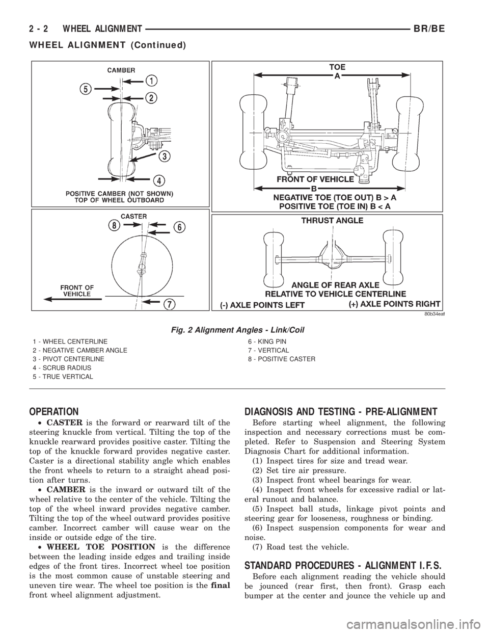
OPERATION
²CASTERis the forward or rearward tilt of the
steering knuckle from vertical. Tilting the top of the
knuckle rearward provides positive caster. Tilting the
top of the knuckle forward provides negative caster.
Caster is a directional stability angle which enables
the front wheels to return to a straight ahead posi-
tion after turns.
²CAMBERis the inward or outward tilt of the
wheel relative to the center of the vehicle. Tilting the
top of the wheel inward provides negative camber.
Tilting the top of the wheel outward provides positive
camber. Incorrect camber will cause wear on the
inside or outside edge of the tire.
²WHEEL TOE POSITIONis the difference
between the leading inside edges and trailing inside
edges of the front tires. Incorrect wheel toe position
is the most common cause of unstable steering and
uneven tire wear. The wheel toe position is thefinal
front wheel alignment adjustment.
DIAGNOSIS AND TESTING - PRE-ALIGNMENT
Before starting wheel alignment, the following
inspection and necessary corrections must be com-
pleted. Refer to Suspension and Steering System
Diagnosis Chart for additional information.
(1) Inspect tires for size and tread wear.
(2) Set tire air pressure.
(3) Inspect front wheel bearings for wear.
(4) Inspect front wheels for excessive radial or lat-
eral runout and balance.
(5) Inspect ball studs, linkage pivot points and
steering gear for looseness, roughness or binding.
(6) Inspect suspension components for wear and
noise.
(7) Road test the vehicle.
STANDARD PROCEDURES - ALIGNMENT I.F.S.
Before each alignment reading the vehicle should
be jounced (rear first, then front). Grasp each
bumper at the center and jounce the vehicle up and
Fig. 2 Alignment Angles - Link/Coil
1 - WHEEL CENTERLINE
2 - NEGATIVE CAMBER ANGLE
3 - PIVOT CENTERLINE
4 - SCRUB RADIUS
5 - TRUE VERTICAL6 - KING PIN
7 - VERTICAL
8 - POSITIVE CASTER
2 - 2 WHEEL ALIGNMENTBR/BE
WHEEL ALIGNMENT (Continued)
Page 276 of 2889
WARNING
WARNING: DUST AND DIRT ACCUMULATING ON
BRAKE PARTS DURING NORMAL USE MAY CON-
TAIN ASBESTOS FIBERS FROM PRODUCTION OR
AFTERMARKET LININGS. BREATHING EXCESSIVE
CONCENTRATIONS OF ASBESTOS FIBERS CAN
CAUSE SERIOUS BODILY HARM. EXERCISE CARE
WHEN SERVICING BRAKE PARTS. DO NOT CLEAN
BRAKE PARTS WITH COMPRESSED AIR OR BY
DRY BRUSHING. USE A VACUUM CLEANER SPE-
CIFICALLY DESIGNED FOR THE REMOVAL OF
ASBESTOS FIBERS FROM BRAKE COMPONENTS.
IF A SUITABLE VACUUM CLEANER IS NOT AVAIL-
ABLE, CLEANING SHOULD BE DONE WITH A
WATER DAMPENED CLOTH. DO NOT SAND, OR
GRIND BRAKE LINING UNLESS EQUIPMENT USED
IS DESIGNED TO CONTAIN THE DUST RESIDUE.
DISPOSE OF ALL RESIDUE CONTAINING ASBES-
TOS FIBERS IN SEALED BAGS OR CONTAINERS
TO MINIMIZE EXPOSURE TO YOURSELF AND OTH-
ERS. FOLLOW PRACTICES PRESCRIBED BY THE
OCCUPATIONAL SAFETY AND HEALTH ADMINIS-
TRATION AND THE ENVIRONMENTAL PROTECTION
AGENCY FOR THE HANDLING, PROCESSING, AND
DISPOSITION OF DUST OR DEBRIS THAT MAY
CONTAIN ASBESTOS FIBERS.
CAUTION: Never use gasoline, kerosene, alcohol,
motor oil, transmission fluid, or any fluid containing
mineral oil to clean the system components. These
fluids damage rubber cups and seals. Use only
fresh brake fluid or Mopar brake cleaner to clean or
flush brake system components. These are the only
cleaning materials recommended. If system contam-
ination is suspected, check the fluid for dirt, discol-
oration, or separation into distinct layers. Also
check the reservoir cap seal for distortion. Drain
and flush the system with new brake fluid if con-
tamination is suspected.
CAUTION: Use Mopar brake fluid, or an equivalent
quality fluid meeting SAE/DOT standards J1703 and
DOT 3. Brake fluid must be clean and free of con-
taminants. Use fresh fluid from sealed containers
only to ensure proper antilock component opera-
tion.
CAUTION: Use Mopar multi-mileage or high temper-
ature grease to lubricate caliper slide surfaces,
drum brake pivot pins, and shoe contact points on
the backing plates. Use multi-mileage grease or GE
661 or Dow 111 silicone grease on caliper slide pins
to ensure proper operation.
DIAGNOSIS AND TESTING - BASE BRAKE
SYSTEM
Base brake components consist of the brake shoes,
calipers, wheel cylinders, brake drums, rotors, brake
lines, master cylinder, booster, and parking brake
components.
Brake diagnosis involves determining if the prob-
lem is related to a mechanical, hydraulic, or vacuum
operated component.
The first diagnosis step is the preliminary check.
PRELIMINARY BRAKE CHECK
(1) Check condition of tires and wheels. Damaged
wheels and worn, damaged, or underinflated tires
can cause pull, shudder, vibration, and a condition
similar to grab.
(2) If complaint was based on noise when braking,
check suspension components. Jounce front and rear
of vehicle and listen for noise that might be caused
by loose, worn or damaged suspension or steering
components.
(3) Inspect brake fluid level and condition. Note
that the brake reservoir fluid level will decrease in
proportion to normal lining wear.Also note that
brake fluid tends to darken over time. This is
normal and should not be mistaken for contam-
ination.
(a) If fluid level is abnormally low, look for evi-
dence of leaks at calipers, wheel cylinders, brake
lines, and master cylinder.
(b) If fluid appears contaminated, drain out a
sample to examine. System will have to be flushed
if fluid is separated into layers, or contains a sub-
stance other than brake fluid. The system seals
and cups will also have to be replaced after flush-
ing. Use clean brake fluid to flush the system.
(4) Check parking brake operation. Verify free
movement and full release of cables and pedal. Also
note if vehicle was being operated with parking
brake partially applied.
(5) Check brake pedal operation. Verify that pedal
does not bind and has adequate free play. If pedal
lacks free play, check pedal and power booster for
being loose or for bind condition. Do not road test
until condition is corrected.
(6) Check booster vacuum check valve and hose.
(7) If components checked appear OK, road test
the vehicle.
ROAD TESTING
(1) If complaint involved low brake pedal, pump
pedal and note if it comes back up to normal height.
(2) Check brake pedal response with transmission
in Neutral and engine running. Pedal should remain
firm under constant foot pressure.
BR/BEBRAKES 5 - 5
HYDRAULIC/MECHANICAL (Continued)
Page 283 of 2889
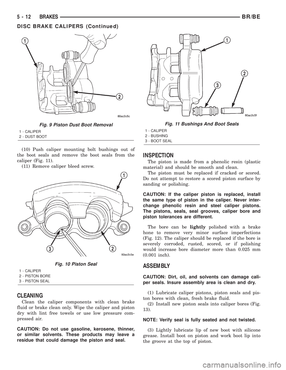
(10) Push caliper mounting bolt bushings out of
the boot seals and remove the boot seals from the
caliper (Fig. 11).
(11) Remove caliper bleed screw.
CLEANING
Clean the caliper components with clean brake
fluid or brake clean only. Wipe the caliper and piston
dry with lint free towels or use low pressure com-
pressed air.
CAUTION: Do not use gasoline, kerosene, thinner,
or similar solvents. These products may leave a
residue that could damage the piston and seal.
INSPECTION
The piston is made from a phenolic resin (plastic
material) and should be smooth and clean.
The piston must be replaced if cracked or scored.
Do not attempt to restore a scored piston surface by
sanding or polishing.
CAUTION: If the caliper piston is replaced, install
the same type of piston in the caliper. Never inter-
change phenolic resin and steel caliper pistons.
The pistons, seals, seal grooves, caliper bore and
piston tolerances are different.
The bore can belightlypolished with a brake
hone to remove very minor surface imperfections
(Fig. 12). The caliper should be replaced if the bore is
severely corroded, rusted, scored, or if polishing
would increase bore diameter more than 0.025 mm
(0.001 inch).
ASSEMBLY
CAUTION: Dirt, oil, and solvents can damage cali-
per seals. Insure assembly area is clean and dry.
(1) Lubricate caliper pistons, piston seals and pis-
ton bores with clean, fresh brake fluid.
(2) Install new piston seals into caliper bores (Fig.
13).
NOTE: Verify seal is fully seated and not twisted.
(3) Lightly lubricate lip of new boot with silicone
grease. Install boot on piston and work boot lip into
the groove at the top of piston.
Fig. 9 Piston Dust Boot Removal
1 - CALIPER
2 - DUST BOOT
Fig. 10 Piston Seal
1 - CALIPER
2 - PISTON BORE
3 - PISTON SEAL
Fig. 11 Bushings And Boot Seals
1 - CALIPER
2 - BUSHING
3 - BOOT SEAL
5 - 12 BRAKESBR/BE
DISC BRAKE CALIPERS (Continued)
Page 315 of 2889
WARNING
WARNING:: EXERCISE CARE WHEN SERVICING
CLUTCH COMPONENTS. FACTORY INSTALLED
CLUTCH DISCS DO NOT CONTAIN ASBESTOS
FIBERS. DUST AND DIRT ON CLUTCH PARTS MAY
CONTAIN ASBESTOS FIBERS FROM AFTERMAR-
KET COMPONENTS. BREATHING EXCESSIVE CON-
CENTRATIONS OF THESE FIBERS CAN CAUSE
SERIOUS BODILY HARM. WEAR A RESPIRATOR
DURING SERVICE AND NEVER CLEAN CLUTCH
COMPONENTS WITH COMPRESSED AIR OR WITH
A DRY BRUSH. EITHER CLEAN THE COMPONENTS
WITH A WATER DAMPENED RAGS OR USE A VAC-
UUM CLEANER SPECIFICALLY DESIGNED FOR
REMOVING ASBESTOS FIBERS AND DUST. DO NOT
CREATE DUST BY SANDING A CLUTCH DISC.
REPLACE THE DISC IF THE FRICTION MATERIAL IS
DAMAGED OR CONTAMINATED. DISPOSE OF ALL
DUST AND DIRT CONTAINING ASBESTOS FIBERS
IN SEALED BAGS OR CONTAINERS. THIS WILL
HELP MINIMIZE EXPOSURE TO YOURSELF AND TO
OTHERS. FOLLOW ALL RECOMMENDED SAFETY
PRACTICES PRESCRIBED BY THE OCCUPATIONAL
SAFETY AND HEALTH ADMINISTRATION (OSHA)
AND THE ENVIRONMENTAL SAFETY AGENCY
(EPA), FOR THE HANDLING AND DISPOSAL OF
PRODUCTS CONTAINING ASBESTOS.
DIAGNOSTIC AND TESTING - CLUTCH
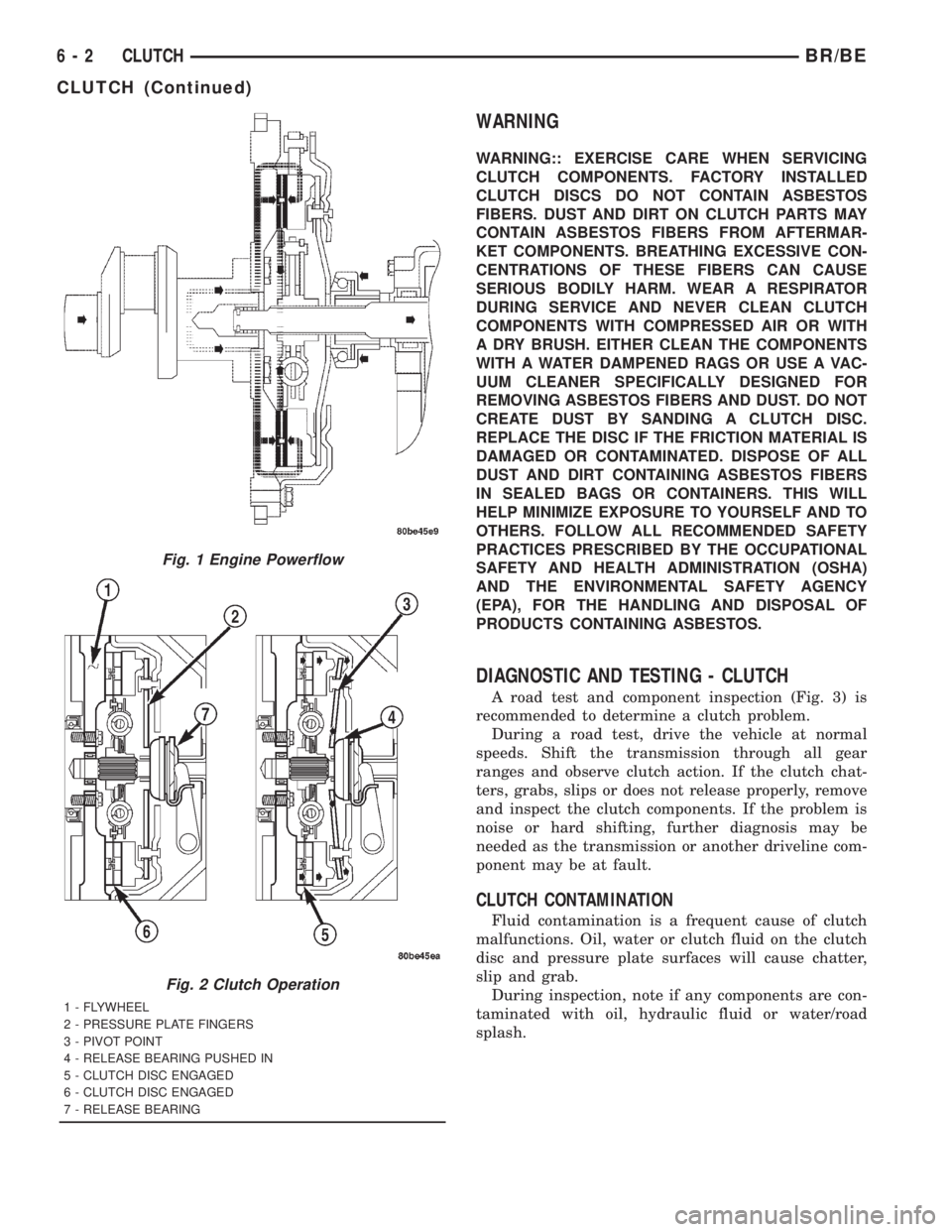
A road test and component inspection (Fig. 3) is
recommended to determine a clutch problem.
During a road test, drive the vehicle at normal
speeds. Shift the transmission through all gear
ranges and observe clutch action. If the clutch chat-
ters, grabs, slips or does not release properly, remove
and inspect the clutch components. If the problem is
noise or hard shifting, further diagnosis may be
needed as the transmission or another driveline com-
ponent may be at fault.
CLUTCH CONTAMINATION
Fluid contamination is a frequent cause of clutch
malfunctions. Oil, water or clutch fluid on the clutch
disc and pressure plate surfaces will cause chatter,
slip and grab.
During inspection, note if any components are con-
taminated with oil, hydraulic fluid or water/road
splash.
Fig. 1 Engine Powerflow
Fig. 2 Clutch Operation
1 - FLYWHEEL
2 - PRESSURE PLATE FINGERS
3 - PIVOT POINT
4 - RELEASE BEARING PUSHED IN
5 - CLUTCH DISC ENGAGED
6 - CLUTCH DISC ENGAGED
7 - RELEASE BEARING
6 - 2 CLUTCHBR/BE
CLUTCH (Continued)
Page 318 of 2889
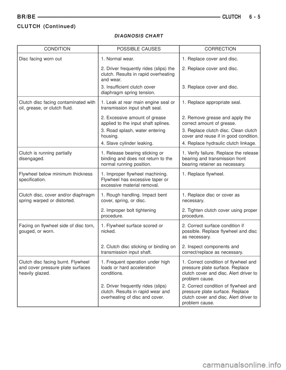
DIAGNOSIS CHART
CONDITION POSSIBLE CAUSES CORRECTION
Disc facing worn out 1. Normal wear. 1. Replace cover and disc.
2. Driver frequently rides (slips) the
clutch. Results in rapid overheating
and wear.2. Replace cover and disc.
3. Insufficient clutch cover
diaphragm spring tension.3. Replace cover and disc.
Clutch disc facing contaminated with
oil, grease, or clutch fluid.1. Leak at rear main engine seal or
transmission input shaft seal.1. Replace appropriate seal.
2. Excessive amount of grease
applied to the input shaft splines.2. Remove grease and apply the
correct amount of grease.
3. Road splash, water entering
housing.3. Replace clutch disc. Clean clutch
cover and reuse if in good condition.
4. Slave cylinder leaking. 4. Replace hydraulic clutch linkage.
Clutch is running partially
disengaged.1. Release bearing sticking or
binding and does not return to the
normal running position.1. Verify failure. Replace the release
bearing and transmission front
bearing retainer as necessary.
Flywheel below minimum thickness
specification.1. Improper flywheel machining.
Flywheel has excessive taper or
excessive material removal.1. Replace flywheel.
Clutch disc, cover and/or diaphragm
spring warped or distorted.1. Rough handling. Impact bent
cover, spring, or disc.1. Replace disc or cover as
necessary.
2. Improper bolt tightening
procedure.2. Tighten clutch cover using proper
procedure.
Facing on flywheel side of disc torn,
gouged, or worn.1. Flywheel surface scored or
nicked.2. Correct surface condition if
possible. Replace flywheel and disc
as necessary.
2. Clutch disc sticking or binding on
transmission input shaft.2. Inspect components and
correct/replace as necessary.
Clutch disc facing burnt. Flywheel
and cover pressure plate surfaces
heavily glazed.1. Frequent operation under high
loads or hard acceleration
conditions.1. Correct condition of flywheel and
pressure plate surface. Replace
clutch cover and disc. Alert driver to
problem cause.
2. Driver frequently rides (slips)
clutch. Results in rapid wear and
overheating of disc and cover.2. Correct condition of flywheel and
pressure plate surface. Replace
clutch cover and disc. Alert driver to
problem cause.
BR/BECLUTCH 6 - 5
CLUTCH (Continued)
Page 336 of 2889
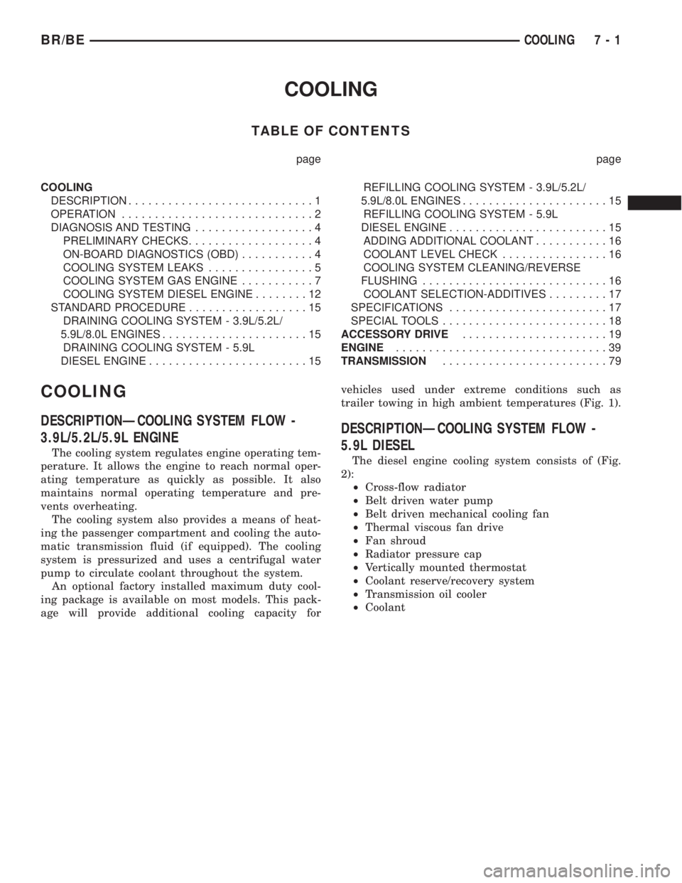
COOLING
TABLE OF CONTENTS
page page
COOLING
DESCRIPTION............................1
OPERATION.............................2
DIAGNOSIS AND TESTING..................4
PRELIMINARY CHECKS...................4
ON-BOARD DIAGNOSTICS (OBD)...........4
COOLING SYSTEM LEAKS................5
COOLING SYSTEM GAS ENGINE...........7
COOLING SYSTEM DIESEL ENGINE........12
STANDARD PROCEDURE..................15
DRAINING COOLING SYSTEM - 3.9L/5.2L/
5.9L/8.0L ENGINES......................15
DRAINING COOLING SYSTEM - 5.9L
DIESEL ENGINE........................15REFILLING COOLING SYSTEM - 3.9L/5.2L/
5.9L/8.0L ENGINES......................15
REFILLING COOLING SYSTEM - 5.9L
DIESEL ENGINE........................15
ADDING ADDITIONAL COOLANT...........16
COOLANT LEVEL CHECK................16
COOLING SYSTEM CLEANING/REVERSE
FLUSHING............................16
COOLANT SELECTION-ADDITIVES.........17
SPECIFICATIONS........................17
SPECIAL TOOLS.........................18
ACCESSORY DRIVE......................19
ENGINE................................39
TRANSMISSION.........................79
COOLING
DESCRIPTIONÐCOOLING SYSTEM FLOW -
3.9L/5.2L/5.9L ENGINE
The cooling system regulates engine operating tem-
perature. It allows the engine to reach normal oper-
ating temperature as quickly as possible. It also
maintains normal operating temperature and pre-
vents overheating.
The cooling system also provides a means of heat-
ing the passenger compartment and cooling the auto-
matic transmission fluid (if equipped). The cooling
system is pressurized and uses a centrifugal water
pump to circulate coolant throughout the system.
An optional factory installed maximum duty cool-
ing package is available on most models. This pack-
age will provide additional cooling capacity forvehicles used under extreme conditions such as
trailer towing in high ambient temperatures (Fig. 1).
DESCRIPTIONÐCOOLING SYSTEM FLOW -
5.9L DIESEL
The diesel engine cooling system consists of (Fig.
2):
²Cross-flow radiator
²Belt driven water pump
²Belt driven mechanical cooling fan
²Thermal viscous fan drive
²Fan shroud
²Radiator pressure cap
²Vertically mounted thermostat
²Coolant reserve/recovery system
²Transmission oil cooler
²Coolant
BR/BECOOLING 7 - 1