auxiliary battery location DODGE RAM 2001 Service Repair Manual
[x] Cancel search | Manufacturer: DODGE, Model Year: 2001, Model line: RAM, Model: DODGE RAM 2001Pages: 2889, PDF Size: 68.07 MB
Page 1421 of 2889

(10)Verify valve lash adjustment (Refer to 9 -
ENGINE/CYLINDER HEAD/INTAKE/EXHAUST
VALVES & SEATS - STANDARD PROCEDURE).
(11)
Install the cylinder head cover and reusable gas-
ket (Fig. 85) (Refer to 9 - ENGINE/CYLINDER HEAD/
CYLINDER HEAD COVER(S) - INSTALLATION).
(12) Install gear housing cover (Refer to 9 -
ENGINE/VALVE TIMING/GEAR HOUSING COVER
- INSTALLATION).
(13) Install the crankshaft damper (Fig. 83) (Refer
to 9 - ENGINE/ENGINE BLOCK/VIBRATION
DAMPER - INSTALLATION).
(14) Install the fan support/hub assembly (Fig. 82)
and tighten bolts to 24 N´m (18 ft. lbs.) torque.
(15) Install the crankcase breather housing (Refer
to 9 - ENGINE - INSTALLATION).
(16) Install the charge air cooler (with a/c con-
denser and auxiliary transmission oil cooler, if
equipped) and tighten the mounting bolts to 2 N´m
(17 in. lbs.) torque.
(17) Connect charge air cooler inlet and outlet
pipes. Tighten clamps to 10 N´m (100 in. lbs.) torque.
(18) Install the radiator upper support panel.
(19) Close radiator petcock and lower the radiator
into the engine compartment. Tighten the mounting
bolts to 11 N´m (95 in. lbs.) torque.
(20) Raise vehicle on hoist.
(21)
Connect radiator lower hose and install clamp.
(22) Connect transmission auxiliary oil cooler lines
(if equipped).
(23) Lower vehicle.
(24) Install the fan shroud and tighten the mount-
ing screws to 6 N´m (50 in. lbs.) torque.(25) Install the viscous fan/drive assembly (Refer
to 7 - COOLING/ENGINE/RADIATOR FAN -
INSTALLATION).
(26) Install the coolant recovery and windshield
washer fluid reservoirs to the fan shroud.
(27) Connect the coolant recovery hose to the radi-
ator filler neck.
(28) Install the accessory drive belt (Refer to 7 -
COOLING/ACCESSORY DRIVE/DRIVE BELTS -
INSTALLATION).
(29) Install the front bumper assembly (Refer to 13
- FRAMES & BUMPERS/BUMPERS/FRONT
BUMPER - INSTALLATION).
(30) Add engine coolant (Refer to 7 - COOLING -
STANDARD PROCEDURE).
(31) Charge A/C system with refrigerant (if A/C
equipped) (Refer to 24 - HEATING & AIR CONDI-
TIONING/PLUMBING - STANDARD PROCEDURE).
(32) Connect the battery negative cables.
(33) Start engine and check for engine oil and cool-
ant leaks.
CONNECTING ROD BEARINGS
STANDARD PROCEDUREÐCONNECTING ROD
BEARING AND CRANKSHAFT JOURNAL
CLEARANCE
Measure the connecting rod bore with the bearings
installed and the bolts tightened to 100 N´m (73 ft.
lbs.) torque.
Record the smaller diameter.
Measure the diameter of the rod journal at the
location shown (Fig. 99). Calculate the average diam-
eter for each side of the journal.
The clearance is the difference between the con-
necting rod bore (smallest diameter) and the average
diameter for each side of the crankshaft journal.
CONNECTING ROD JOURNAL DIAMETER
LIMITS CHART
DESCRIPTION MEASUREMENT
CRANKSHAFT ROD
JOURNAL DIAMETERMINIMUM 68.962 mm
(2.715 in.)
MAXIMUM 69.013 mm
(2.717 in.)
OUT-OF-ROUND MAXIMUM 0.050 mm
(0.002 in.)
TAPER MAXIMUM 0.013 mm
(0.0005 in.)
BEARING CLEARANCE MAXIMUM 0.089 mm
(0.0035 in.)
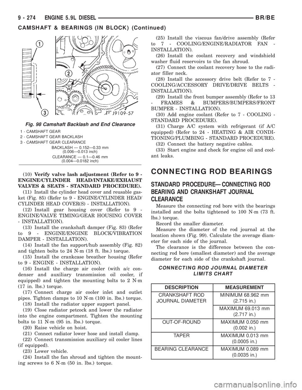
Fig. 98 Camshaft Backlash and End Clearance
1 - CAMSHAFT GEAR
2 - CAMSHAFT GEAR BACKLASH
3 - CAMSHAFT GEAR CLEARANCE
BACKLASH Ð 0.152Ð0.33 mm
(0.006Ð0.013 inch)
CLEARANCE Ð 0.1Ð0.46 mm
(0.004Ð0.0182 inch)
9 - 274 ENGINE 5.9L DIESELBR/BE
CAMSHAFT & BEARINGS (IN BLOCK) (Continued)
Page 1512 of 2889

(b) Type 2: Separate and unlatch 2 small arms
on end of clip (Fig. 47) and swing away from fuel
line.
(c) Slide latch clip toward fuel rail while lifting
with screwdriver.
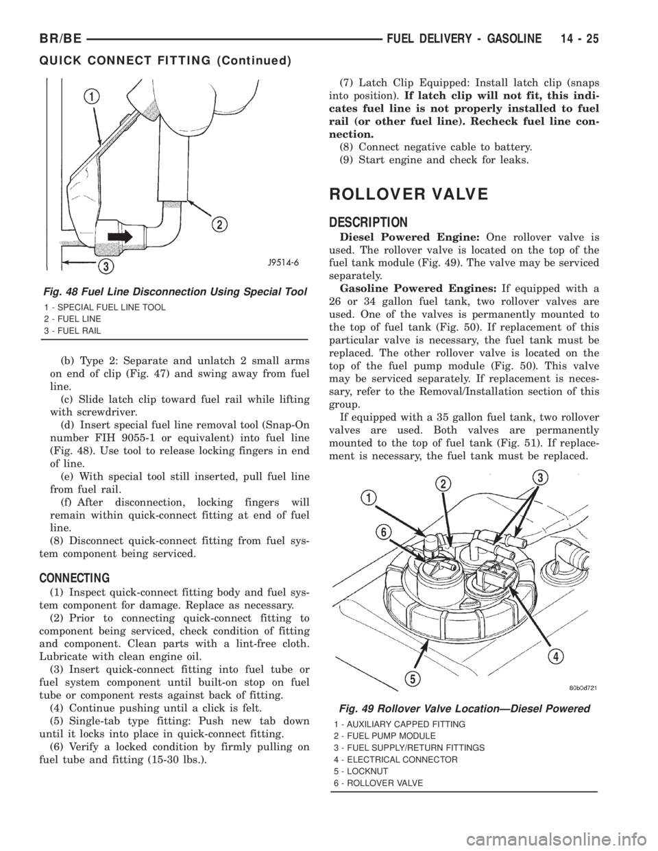
(d) Insert special fuel line removal tool (Snap-On
number FIH 9055-1 or equivalent) into fuel line
(Fig. 48). Use tool to release locking fingers in end
of line.
(e) With special tool still inserted, pull fuel line
from fuel rail.
(f) After disconnection, locking fingers will
remain within quick-connect fitting at end of fuel
line.
(8) Disconnect quick-connect fitting from fuel sys-
tem component being serviced.
CONNECTING
(1) Inspect quick-connect fitting body and fuel sys-
tem component for damage. Replace as necessary.
(2) Prior to connecting quick-connect fitting to
component being serviced, check condition of fitting
and component. Clean parts with a lint-free cloth.
Lubricate with clean engine oil.
(3) Insert quick-connect fitting into fuel tube or
fuel system component until built-on stop on fuel
tube or component rests against back of fitting.
(4) Continue pushing until a click is felt.
(5) Single-tab type fitting: Push new tab down
until it locks into place in quick-connect fitting.
(6) Verify a locked condition by firmly pulling on
fuel tube and fitting (15-30 lbs.).(7) Latch Clip Equipped: Install latch clip (snaps
into position).If latch clip will not fit, this indi-
cates fuel line is not properly installed to fuel
rail (or other fuel line). Recheck fuel line con-
nection.
(8) Connect negative cable to battery.
(9) Start engine and check for leaks.
ROLLOVER VALVE
DESCRIPTION
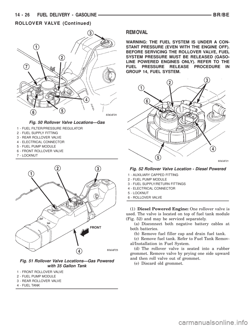
Diesel Powered Engine:One rollover valve is
used. The rollover valve is located on the top of the
fuel tank module (Fig. 49). The valve may be serviced
separately.
Gasoline Powered Engines:If equipped with a
26 or 34 gallon fuel tank, two rollover valves are
used. One of the valves is permanently mounted to
the top of fuel tank (Fig. 50). If replacement of this
particular valve is necessary, the fuel tank must be
replaced. The other rollover valve is located on the
top of the fuel pump module (Fig. 50). This valve
may be serviced separately. If replacement is neces-
sary, refer to the Removal/Installation section of this
group.
If equipped with a 35 gallon fuel tank, two rollover
valves are used. Both valves are permanently
mounted to the top of fuel tank (Fig. 51). If replace-
ment is necessary, the fuel tank must be replaced.
Fig. 48 Fuel Line Disconnection Using Special Tool
1 - SPECIAL FUEL LINE TOOL
2 - FUEL LINE
3 - FUEL RAIL
Fig. 49 Rollover Valve LocationÐDiesel Powered
1 - AUXILIARY CAPPED FITTING
2 - FUEL PUMP MODULE
3 - FUEL SUPPLY/RETURN FITTINGS
4 - ELECTRICAL CONNECTOR
5 - LOCKNUT
6 - ROLLOVER VALVE
BR/BEFUEL DELIVERY - GASOLINE 14 - 25
QUICK CONNECT FITTING (Continued)
Page 1513 of 2889

REMOVAL
WARNING: THE FUEL SYSTEM IS UNDER A CON-
STANT PRESSURE (EVEN WITH THE ENGINE OFF).
BEFORE SERVICING THE ROLLOVER VALVE, FUEL
SYSTEM PRESSURE MUST BE RELEASED (GASO-
LINE POWERED ENGINES ONLY). REFER TO THE
FUEL PRESSURE RELEASE PROCEDURE IN
GROUP 14, FUEL SYSTEM.
(1)Diesel Powered Engine:One rollover valve is
used. The valve is located on top of fuel tank module
(Fig. 52) and may be serviced separately.
(a) Disconnect both negative battery cables at
both batteries.
(b) Remove fuel filler cap and drain fuel tank.
(c) Remove fuel tank. Refer to Fuel Tank Remov-
al/Installation in Fuel System.
(d) The rollover valve is seated into a rubber
grommet. Remove valve by prying one side upward
and then roll valve out of grommet.
(e) Discard old grommet.
Fig. 50 Rollover Valve LocationsÐGas
1 - FUEL FILTER/PRESSURE REGULATOR
2 - FUEL SUPPLY FITTING
3 - REAR ROLLOVER VALVE
4 - ELECTRICAL CONNECTOR
5 - FUEL PUMP MODULE
6 - FRONT ROLLOVER VALVE
7 - LOCKNUT
Fig. 51 Rollover Valve LocationsÐGas Powered
with 35 Gallon Tank
1 - FRONT ROLLOVER VALVE
2 - FUEL PUMP MODULE
3 - REAR ROLLOVER VALVE
4 - FUEL TANK
Fig. 52 Rollover Valve Location - Diesel Powered
1 - AUXILIARY CAPPED FITTING
2 - FUEL PUMP MODULE
3 - FUEL SUPPLY/RETURN FITTINGS
4 - ELECTRICAL CONNECTOR
5 - LOCKNUT
6 - ROLLOVER VALVE
14 - 26 FUEL DELIVERY - GASOLINEBR/BE
ROLLOVER VALVE (Continued)