rear axle corporate DODGE RAM 2001 Service Repair Manual
[x] Cancel search | Manufacturer: DODGE, Model Year: 2001, Model line: RAM, Model: DODGE RAM 2001Pages: 2889, PDF Size: 68.07 MB
Page 76 of 2889
Before undercoating a vehicle, the propeller
shaft and the U-joints should be covered to pre-
vent an out-of-balance condition and driveline
vibration.
CAUTION: Use original equipment replacement
parts for attaching the propeller shafts. The speci-
fied torque must always be applied when tightening
the fasteners.
DIAGNOSIS AND TESTING - PROPELLER
SHAFT
VIBRATION
Tires that are out-of-round, or wheels that are
unbalanced, will cause a low frequency vibration.
(Refer to 22 - TIRES/WHEELS - DIAGNOSIS AND
TESTING)
Brake drums that are unbalanced will cause a
harsh, low frequency vibration. (Refer to 5 - BRAKES
- DIAGNOSIS AND TESTING)
Driveline vibration can also result from loose or
damaged engine mounts.
Propeller shaft vibration increases as the vehicle
speed is increased. A vibration that occurs within a
specific speed range is not usually caused by a pro-
peller shaft being unbalanced. Defective universal
joints, or an incorrect propeller shaft angle, are usu-
ally the cause of such a vibration.
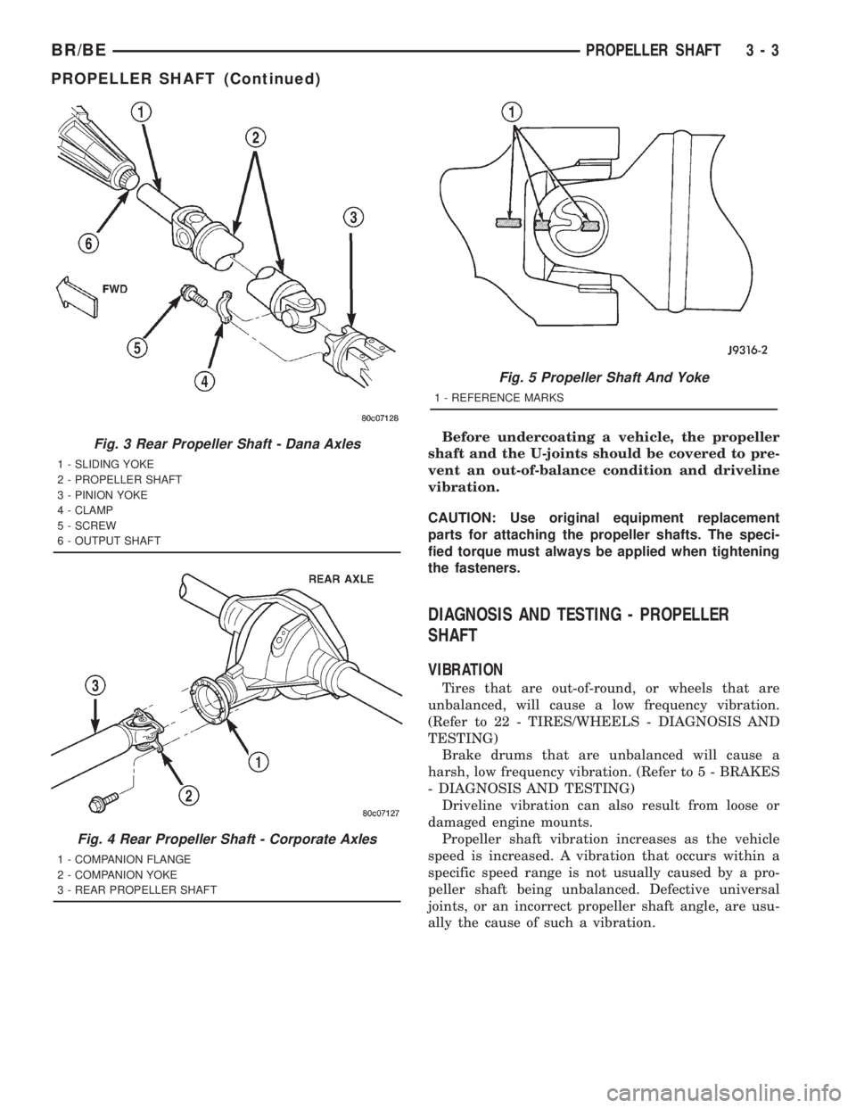
Fig. 3 Rear Propeller Shaft - Dana Axles
1 - SLIDING YOKE
2 - PROPELLER SHAFT
3 - PINION YOKE
4 - CLAMP
5 - SCREW
6 - OUTPUT SHAFT
Fig. 4 Rear Propeller Shaft - Corporate Axles
1 - COMPANION FLANGE
2 - COMPANION YOKE
3 - REAR PROPELLER SHAFT
Fig. 5 Propeller Shaft And Yoke
1 - REFERENCE MARKS
BR/BEPROPELLER SHAFT 3 - 3
PROPELLER SHAFT (Continued)
Page 82 of 2889
PROPELLER SHAFT - REAR
REMOVAL
(1) Raise and support vehicle on safety stands.
(2) Shift the transmission to the Neutral position.
(3) Using a suitable marker, mark a line across
the axle pinion yoke, or companion flange, and the
propeller shaft, or flange yoke for installation refer-
ence.
(4) Using a suitable marker, mark the outline of
the center bearing on the frame crossmember for
installation reference, if equipped.
(5) Remove bolts that attach the center bearing to
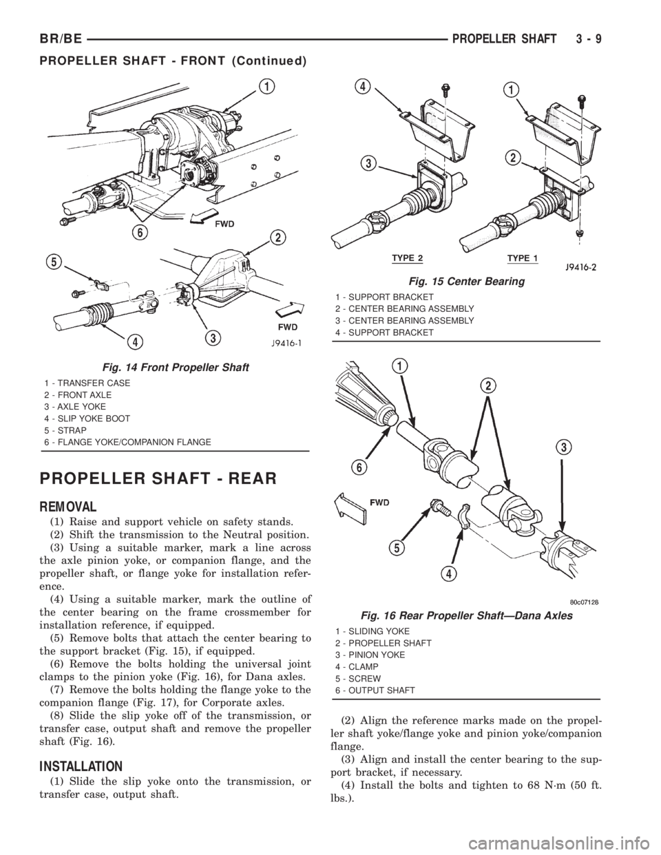
the support bracket (Fig. 15), if equipped.
(6) Remove the bolts holding the universal joint
clamps to the pinion yoke (Fig. 16), for Dana axles.
(7) Remove the bolts holding the flange yoke to the
companion flange (Fig. 17), for Corporate axles.
(8) Slide the slip yoke off of the transmission, or
transfer case, output shaft and remove the propeller
shaft (Fig. 16).
INSTALLATION
(1) Slide the slip yoke onto the transmission, or
transfer case, output shaft.(2) Align the reference marks made on the propel-
ler shaft yoke/flange yoke and pinion yoke/companion
flange.
(3) Align and install the center bearing to the sup-
port bracket, if necessary.
(4) Install the bolts and tighten to 68 N´m (50 ft.
lbs.).
Fig. 14 Front Propeller Shaft
1 - TRANSFER CASE
2 - FRONT AXLE
3 - AXLE YOKE
4 - SLIP YOKE BOOT
5 - STRAP
6 - FLANGE YOKE/COMPANION FLANGE
Fig. 15 Center Bearing
1 - SUPPORT BRACKET
2 - CENTER BEARING ASSEMBLY
3 - CENTER BEARING ASSEMBLY
4 - SUPPORT BRACKET
Fig. 16 Rear Propeller ShaftÐDana Axles
1 - SLIDING YOKE
2 - PROPELLER SHAFT
3 - PINION YOKE
4 - CLAMP
5 - SCREW
6 - OUTPUT SHAFT
BR/BEPROPELLER SHAFT 3 - 9
PROPELLER SHAFT - FRONT (Continued)
Page 83 of 2889
(5) Position universal joint into pinion yoke for
Dana axles and tighten strap bolts to 29 N´m (22 ft.
lbs.).
(6) Position companion yoke onto the companion
flange for Corporate axles and tighten the bolts to
108 N´m (80 ft. lbs.).
(7) Lower the vehicle.
CENTER BEARING
DESCRIPTION
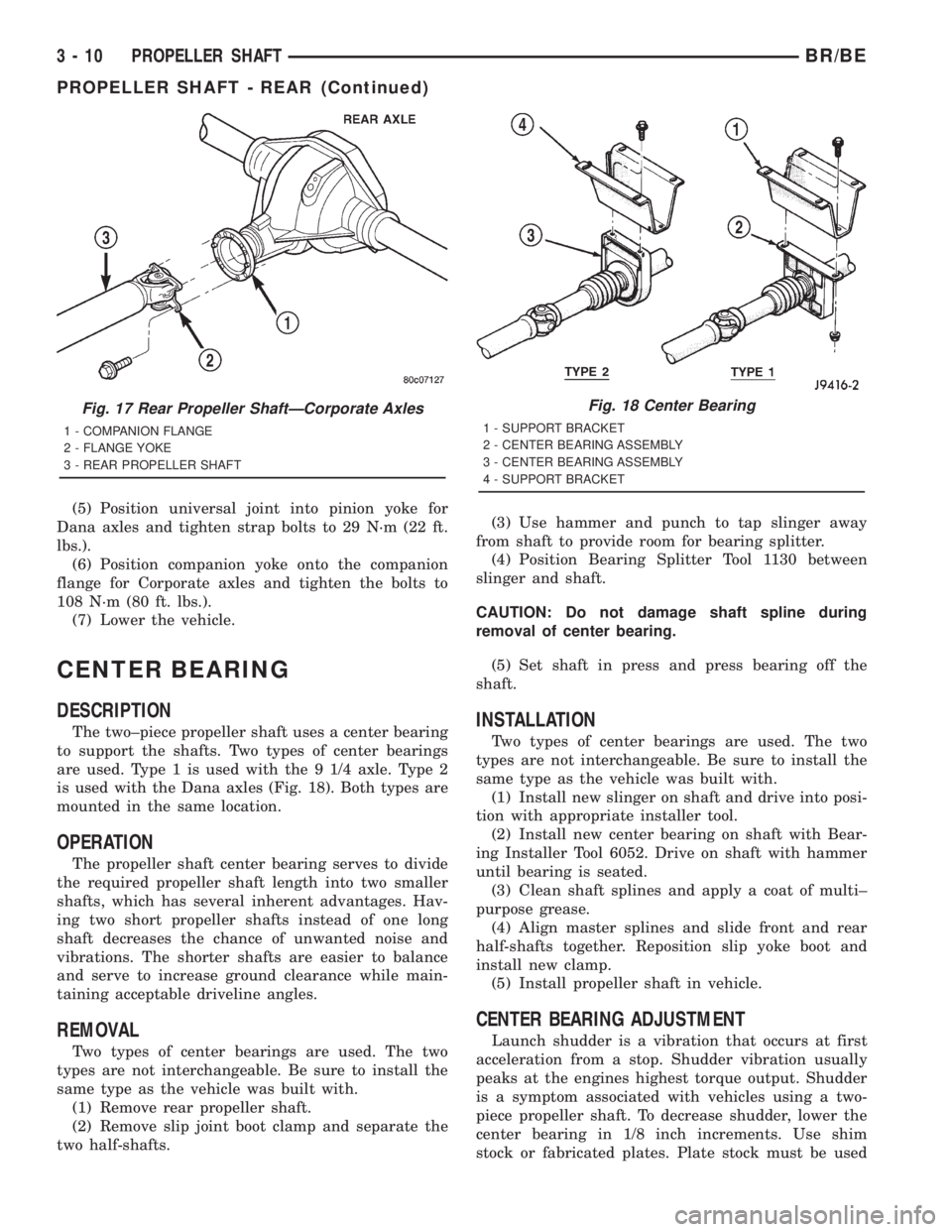
The two±piece propeller shaft uses a center bearing
to support the shafts. Two types of center bearings
are used. Type 1 is used with the 9 1/4 axle. Type 2
is used with the Dana axles (Fig. 18). Both types are
mounted in the same location.
OPERATION
The propeller shaft center bearing serves to divide
the required propeller shaft length into two smaller
shafts, which has several inherent advantages. Hav-
ing two short propeller shafts instead of one long
shaft decreases the chance of unwanted noise and
vibrations. The shorter shafts are easier to balance
and serve to increase ground clearance while main-
taining acceptable driveline angles.
REMOVAL
Two types of center bearings are used. The two
types are not interchangeable. Be sure to install the
same type as the vehicle was built with.
(1) Remove rear propeller shaft.
(2) Remove slip joint boot clamp and separate the
two half-shafts.(3) Use hammer and punch to tap slinger away
from shaft to provide room for bearing splitter.
(4) Position Bearing Splitter Tool 1130 between
slinger and shaft.
CAUTION: Do not damage shaft spline during
removal of center bearing.
(5) Set shaft in press and press bearing off the
shaft.
INSTALLATION
Two types of center bearings are used. The two
types are not interchangeable. Be sure to install the
same type as the vehicle was built with.
(1) Install new slinger on shaft and drive into posi-
tion with appropriate installer tool.
(2) Install new center bearing on shaft with Bear-
ing Installer Tool 6052. Drive on shaft with hammer
until bearing is seated.
(3) Clean shaft splines and apply a coat of multi±
purpose grease.
(4) Align master splines and slide front and rear
half-shafts together. Reposition slip yoke boot and
install new clamp.
(5) Install propeller shaft in vehicle.
CENTER BEARING ADJUSTMENT
Launch shudder is a vibration that occurs at first
acceleration from a stop. Shudder vibration usually
peaks at the engines highest torque output. Shudder
is a symptom associated with vehicles using a two-
piece propeller shaft. To decrease shudder, lower the
center bearing in 1/8 inch increments. Use shim
stock or fabricated plates. Plate stock must be used
Fig. 17 Rear Propeller ShaftÐCorporate Axles
1 - COMPANION FLANGE
2 - FLANGE YOKE
3 - REAR PROPELLER SHAFT
Fig. 18 Center Bearing
1 - SUPPORT BRACKET
2 - CENTER BEARING ASSEMBLY
3 - CENTER BEARING ASSEMBLY
4 - SUPPORT BRACKET
3 - 10 PROPELLER SHAFTBR/BE
PROPELLER SHAFT - REAR (Continued)