sensor DODGE RAM 2002 Service Repair Manual
[x] Cancel search | Manufacturer: DODGE, Model Year: 2002, Model line: RAM, Model: DODGE RAM 2002Pages: 2255, PDF Size: 62.07 MB
Page 1212 of 2255
(b) Install the rear line bundle (cyls. #3, 5, and
6), and tighten the threads at the head and pump
by hand.
(c) Torque the connections at the cylinder head
first. Torque connections to 38 N´m (28 ft. lbs.).
(d) Torque the line connections at the injection
pump to 24 N´m (18 ft. lbs.).
(e) Install the front line bundle (cyls. #1, 2, and
4) following the same procedure used for the rear
line bundle.
(f) Torque the connections at the cylinder head
first. Torque connections to 38 N´m (28 ft. lbs.).
(g) Torque the line connections at the injection
pump to 24 N´m (18 ft. lbs.).
(h) Install the injection line support bracket to
intake cover/cylinder head bolts and torque to 24
N´m (18 ft. lbs.).
(16) Install the engine lift bracket at the rear of
cylinder head. Torque to 77 N´m (57 ft. lbs.).
(17) Install the fuel filter to injection pump low
pressure line. Inspect and replace sealing washers if
necessary. Torque banjo bolts to 24 N´m (18 ft. lbs.).
(18) Using new gaskets, install the intake grid
heater and air inlet housing. Torque bolts to 24 N´m
(18 ft. lbs.).(19) Connect the APPS connector (Fig. 17).
(20) Install the APPS assembly. to the cylinder
head bracket and torque bolts to 12 N´m (105 in.
lbs.).
(21) Install the throttle linkage cover (Fig. 15).
(22) Install the charge air cooler-to-air inlet hous-
ing duct assembly. Torque all clamps to 11 N´m (100
in. lbs.).
(23) Connect intake grid heater wires.
(24) Fasten engine harness to front of cylinder
head with bolt.
(25) Install engine harness ground wire and torque
bolt to 24 N´m (18 ft. lbs.).
(26) Connect engine coolant temperature sensor
connector.
(27) Connect radiator upper hose to thermostat
housing.
(28) Install generator upper bracket and torque
bolts to 41 N´m (31 ft. lbs.).
(29) Install accessory drive belt (Refer to 7 -
COOLING/ACCESSORY DRIVE/DRIVE BELTS -
INSTALLATION).
(30) Install exhaust manifold/turbocharger assem-
bly. and start all bolts/spacers by hand. Torque bolts
to 43 N´m (32 ft. lbs.).
(31) Connect turbocharger oil drain tube.
(32) Perform the turbocharger pre-lube procedure.
Refer to Group 11, Exhaust System and Turbo-
charger for the correct procedure.
(33) Connect the turbocharger oil supply line.
(34) Install air cleaner housing and duct.
(35) Raise vehicle on hoist.
(36) Install exhaust pipe to turbocharger elbow
(Fig. 14). Torque bolts to 34 N´m (25 ft. lbs.).
(37) Lower vehicle.
(38) Fill engine coolant (Refer to 7 - COOLING -
STANDARD PROCEDURE).
(39) Start engine and check for leaks.
CYLINDER HEAD COVER(S)
REMOVAL
(1) Disconnect both battery negative cables.
(2) Loosen the five (5) cylinder head cover bolts
(Fig. 34) . Remove the front three bolts and leave the
rear two bolts in the cover.
(3) Lift cover off of cylinder head.
CLEANING
Using a suitable solvent, Clean and dry gasket
mating surfaces on cylinder head and cover. Wipe
gasket dry and inspect for re-use.
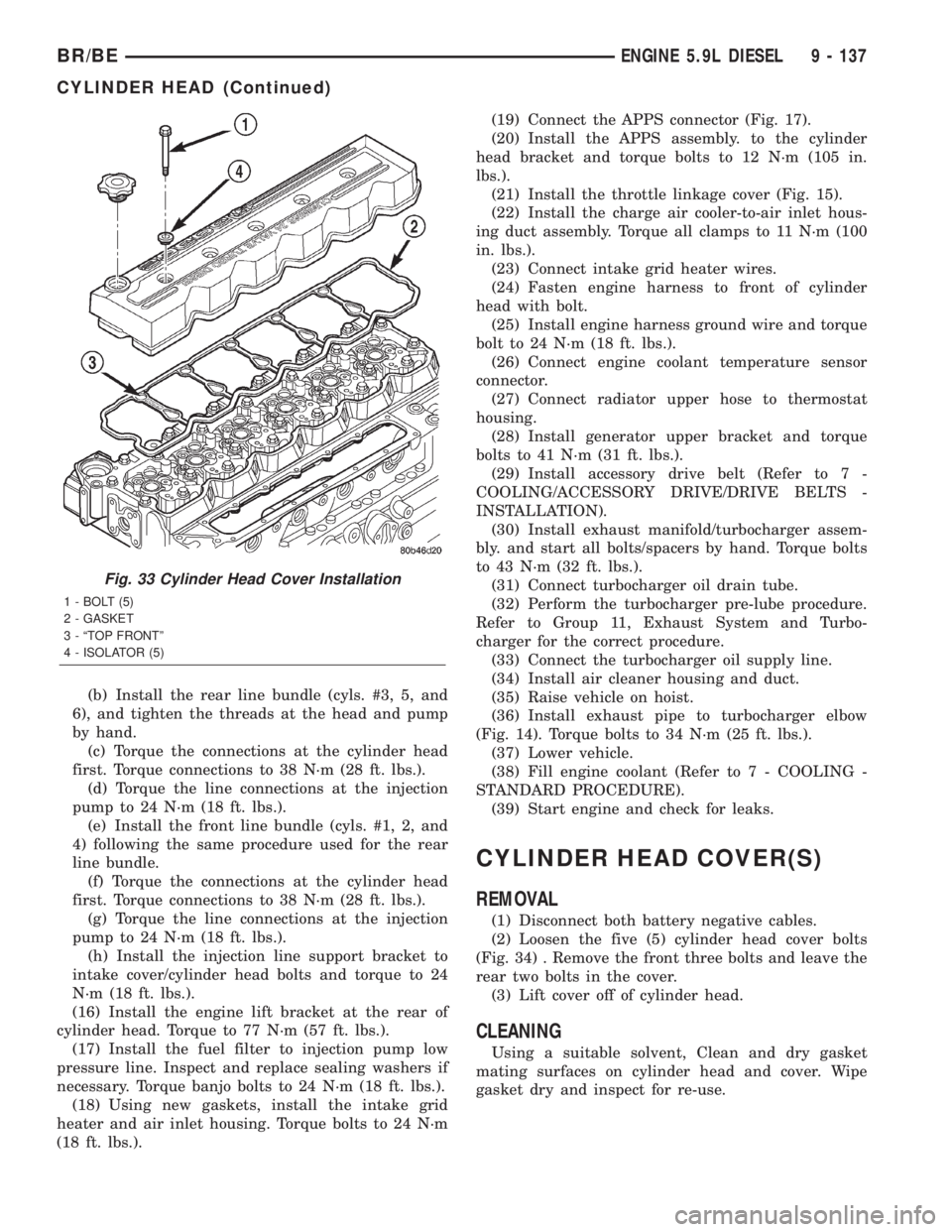
Fig. 33 Cylinder Head Cover Installation
1 - BOLT (5)
2 - GASKET
3 - ªTOP FRONTº
4 - ISOLATOR (5)
BR/BEENGINE 5.9L DIESEL 9 - 137
CYLINDER HEAD (Continued)
Page 1253 of 2255
DIAGNOSIS AND TESTINGÐENGINE OIL
PRESSURE
(1) Remove the engine oil pressure sensor and
install Oil Pressure Line and Gauge Tool C-3292 with
a suitable adapter.
(2) Start engine and warm to operating tempera-
ture.
(3) Record engine oil pressure and compare with
engine oil pressure chart.
CAUTION: If engine oil pressure is zero at idle, DO
NOT RUN THE ENGINE.
Engine Oil Pressure (MIN)
At Idle 103.4 kPa (15 psi)
At 2000 rpm 310.2 kPa (45 psi)
If minimum engine oil pressure is below these
ranges, (Refer to 9 - ENGINE - DIAGNOSIS AND
TESTING).
(4) Remove oil pressure gauge and install the oil
pressure sensor. Tighten the sensor to 16 N´m (144
in. lbs.) torque.
OIL
STANDARD PROCEDURE
STANDARD PROCEDURE - ENGINE OIL LEVEL
CAUTION: Do not overfill crankcase with engine oil,
oil foaming and oil pressure loss can result.
To ensure proper lubrication of an engine, the
engine oil must be maintained at an acceptable level.
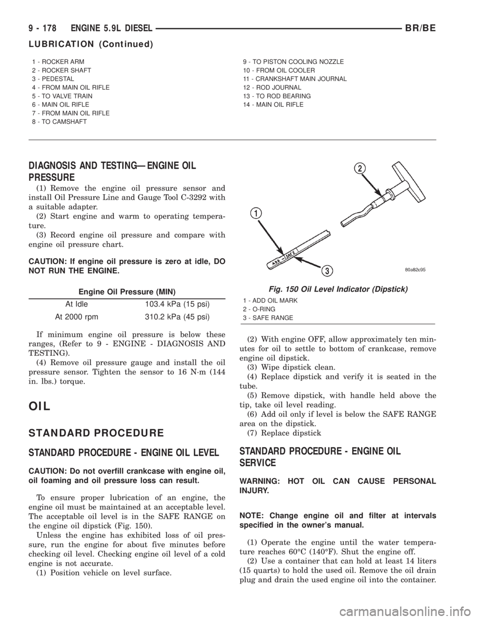
The acceptable oil level is in the SAFE RANGE on
the engine oil dipstick (Fig. 150).
Unless the engine has exhibited loss of oil pres-
sure, run the engine for about five minutes before
checking oil level. Checking engine oil level of a cold
engine is not accurate.
(1) Position vehicle on level surface.(2) With engine OFF, allow approximately ten min-
utes for oil to settle to bottom of crankcase, remove
engine oil dipstick.
(3) Wipe dipstick clean.
(4) Replace dipstick and verify it is seated in the
tube.
(5) Remove dipstick, with handle held above the
tip, take oil level reading.
(6) Add oil only if level is below the SAFE RANGE
area on the dipstick.
(7) Replace dipstick
STANDARD PROCEDURE - ENGINE OIL
SERVICE
WARNING: HOT OIL CAN CAUSE PERSONAL
INJURY.
NOTE: Change engine oil and filter at intervals
specified in the owner's manual.
(1) Operate the engine until the water tempera-
ture reaches 60ÉC (140ÉF). Shut the engine off.
(2) Use a container that can hold at least 14 liters
(15 quarts) to hold the used oil. Remove the oil drain
plug and drain the used engine oil into the container.
1 - ROCKER ARM
2 - ROCKER SHAFT
3 - PEDESTAL
4 - FROM MAIN OIL RIFLE
5 - TO VALVE TRAIN
6 - MAIN OIL RIFLE
7 - FROM MAIN OIL RIFLE
8 - TO CAMSHAFT9 - TO PISTON COOLING NOZZLE
10 - FROM OIL COOLER
11 - CRANKSHAFT MAIN JOURNAL
12 - ROD JOURNAL
13 - TO ROD BEARING
14 - MAIN OIL RIFLE
Fig. 150 Oil Level Indicator (Dipstick)
1 - ADD OIL MARK
2 - O-RING
3 - SAFE RANGE
9 - 178 ENGINE 5.9L DIESELBR/BE
LUBRICATION (Continued)
Page 1256 of 2255
OIL PRESSURE SENSOR/
SWITCH
REMOVAL
(1) Disconnect the battery negative cables.
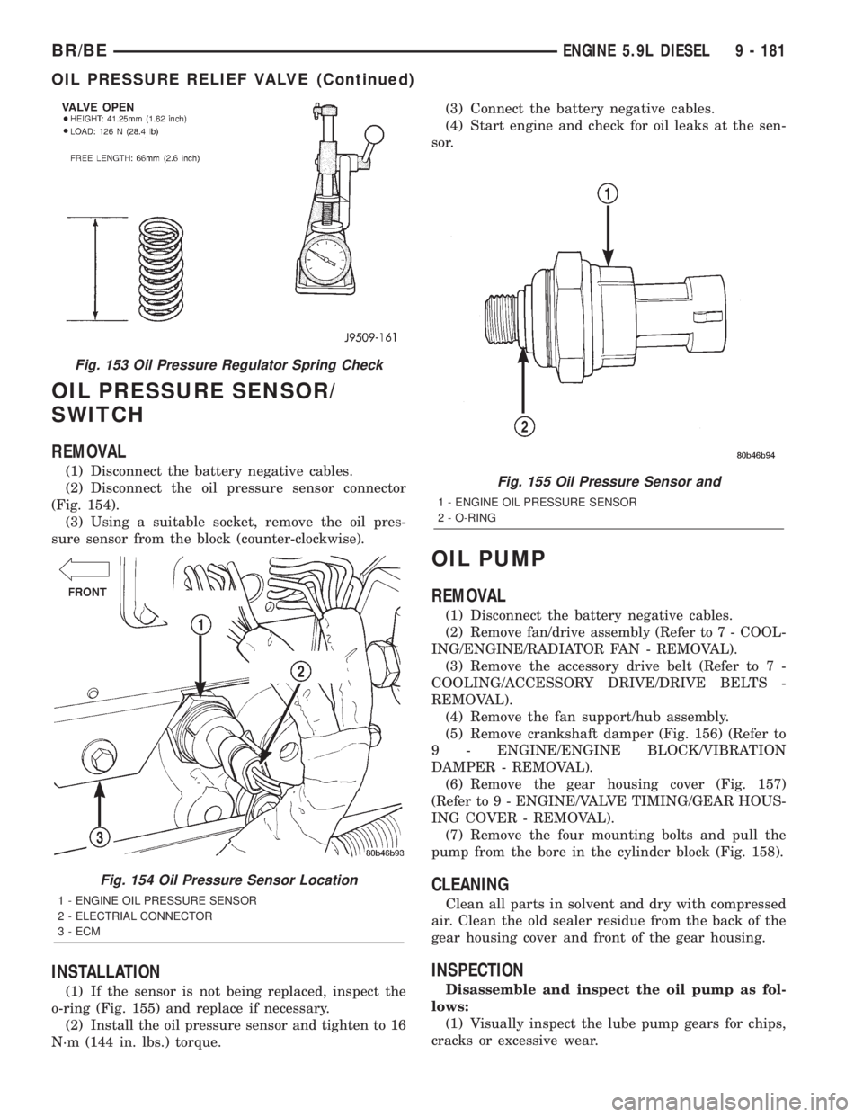
(2) Disconnect the oil pressure sensor connector
(Fig. 154).
(3) Using a suitable socket, remove the oil pres-
sure sensor from the block (counter-clockwise).
INSTALLATION
(1) If the sensor is not being replaced, inspect the
o-ring (Fig. 155) and replace if necessary.
(2) Install the oil pressure sensor and tighten to 16
N´m (144 in. lbs.) torque.(3) Connect the battery negative cables.
(4) Start engine and check for oil leaks at the sen-
sor.
OIL PUMP
REMOVAL
(1) Disconnect the battery negative cables.
(2) Remove fan/drive assembly (Refer to 7 - COOL-
ING/ENGINE/RADIATOR FAN - REMOVAL).
(3) Remove the accessory drive belt (Refer to 7 -
COOLING/ACCESSORY DRIVE/DRIVE BELTS -
REMOVAL).
(4) Remove the fan support/hub assembly.
(5) Remove crankshaft damper (Fig. 156) (Refer to
9 - ENGINE/ENGINE BLOCK/VIBRATION
DAMPER - REMOVAL).
(6) Remove the gear housing cover (Fig. 157)
(Refer to 9 - ENGINE/VALVE TIMING/GEAR HOUS-
ING COVER - REMOVAL).
(7) Remove the four mounting bolts and pull the
pump from the bore in the cylinder block (Fig. 158).
CLEANING
Clean all parts in solvent and dry with compressed
air. Clean the old sealer residue from the back of the
gear housing cover and front of the gear housing.
INSPECTION
Disassemble and inspect the oil pump as fol-
lows:
(1) Visually inspect the lube pump gears for chips,
cracks or excessive wear.
Fig. 155 Oil Pressure Sensor and
1 - ENGINE OIL PRESSURE SENSOR
2 - O-RING
Fig. 153 Oil Pressure Regulator Spring Check
Fig. 154 Oil Pressure Sensor Location
1 - ENGINE OIL PRESSURE SENSOR
2 - ELECTRIAL CONNECTOR
3 - ECM
BR/BEENGINE 5.9L DIESEL 9 - 181
OIL PRESSURE RELIEF VALVE (Continued)
Page 1262 of 2255
(7) Position the charge air cooler inlet pipe to the
turbocharger. With the clamp in position, tighten the
clamp nut to 8 N´m (72 in. lbs.) torque.
(8) Position the air inlet hose to the turbocharger
(Fig. 170). Tighten the clamp to 8 N´m (72 in. lbs.)
torque.
(9) Raise vehicle on hoist.
(10) Connect the exhaust pipe to the turbocharger
(Fig. 169) and tighten the bolts to 34 N´m (25 ft. lbs.)
torque.
(11) Lower the vehicle.
(12) Connect the battery negative cables.
(13) Start the engine to check for leaks.
VALVE TIMING
STANDARD PROCEDURE - TIMING
VERIFICATION
(1) Remove the cylinder head cover.
(2) Remove fuel injector from cylinder number 1.
(3) Remove the crankcase breather from the gear
housing cover.
(4) Using Special Tool 7471B rotate the engine
until the timing mark on the fuel pump gear is
aligned with the TDC mark on the gear housing
cover.
(5) Using a 8 in.x 1/4 in. dowel rod inserted into
cylinder number 1, rock the crankshaft back and
forth to verify piston number 1 is at TDC.
(6) With piston number 1 at TDC the timing mark
on the fuel pump gear should be aligned with the
TDC mark on the gear housing cover. If marks do not
line up, remove the gear housing cover.
(7) With cylinder number still at TDC, inspect the
keyway on the crankshaft gear for proper alignment
(12 o'clock position).
(8) If the keyway is not at 12 o'clock position
replace the crankshaft gear assembly.
(9) If the keyway is at 12 o'clock position, verify
timing mark alignment between the camshaft gear,
crankshaft gear and the fuel pump gear, if not
aligned inspect keyway on camshaft gear.
(10) Inspect keyway on camshaft gear for proper
alignment with the key in the camshaft, if alignment
is off replace the camshaft/gear assembly.
(11) If timing marks alignment is off and no dam-
age is found at either the crankshaft or camshaft
gear keyways, realign timing marks as necessary.
GEAR HOUSING
REMOVAL
(1) Disconnect the battery negative cables.
(2) Raise vehicle on hoist.(3) Partially drain engine coolant into container
suitable for re-use (Refer to 7 - COOLING - STAN-
DARD PROCEDURE).
(4) Lower vehicle.
(5) Remove radiator upper hose.
(6) Disconnect coolant recovery bottle hose from
radiator filler neck and lift bottle off of fan shroud.
(7) Disconnect windshield washer pump supply
hose and electrical connections and lift washer bottle
off of fan shroud.
(8) Remove the fan shroud-to-radiator mounting
bolts.
(9) Remove viscous fan/drive assembly (Refer to 7 -
COOLING/ENGINE/RADIATOR FAN - REMOVAL).
(10) Remove the accessory drive belt (Refer to 7 -
COOLING/ACCESSORY DRIVE/DRIVE BELTS -
REMOVAL).
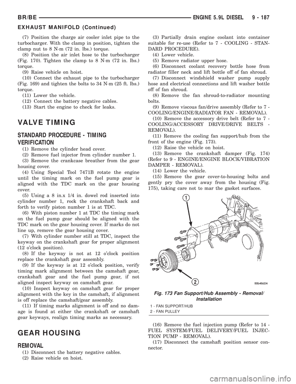
(11) Remove the cooling fan support/hub from the
front of the engine (Fig. 173).
(12) Raise the vehicle on hoist.
(13) Remove the crankshaft damper (Fig. 174)
(Refer to 9 - ENGINE/ENGINE BLOCK/VIBRATION
DAMPER - REMOVAL).
(14) Lower the vehicle.
(15) Remove the gear cover-to-housing bolts and
gently pry the cover away from the housing (Fig.
175), taking care not to mar the gasket surfaces.
(16) Remove the fuel injection pump (Refer to 14 -
FUEL SYSTEM/FUEL DELIVERY/FUEL INJEC-
TION PUMP - REMOVAL).
(17) Disconnect the camshaft position sensor con-
nector.
Fig. 173 Fan Support/Hub Assembly - Removal/
Installation
1 - FAN SUPPORT/HUB
2 - FAN PULLEY
BR/BEENGINE 5.9L DIESEL 9 - 187
EXHAUST MANIFOLD (Continued)
Page 1264 of 2255
(8) Install and tighten the gear housing bolts to 24
N´m (18 ft. lbs.) torque.
(9) Install and tighten the oil pan bolts to 24 N´m
(18 ft. lbs.) torque.
(10) Install the camshaft (Refer to 9 - ENGINE/
ENGINE BLOCK/CAMSHAFT & BEARINGS (IN
BLOCK) - INSTALLATION). Align the crankshaft,
camshaft, and injection pump gear marks as shown
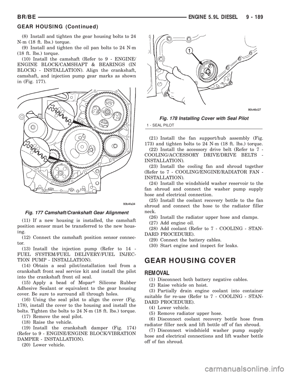
in (Fig. 177).
(11) If a new housing is installed, the camshaft
position sensor must be transferred to the new hous-
ing.
(12) Connect the camshaft position sensor connec-
tor.
(13) Install the injection pump (Refer to 14 -
FUEL SYSTEM/FUEL DELIVERY/FUEL INJEC-
TION PUMP - INSTALLATION).
(14) Obtain a seal pilot/installation tool from a
crankshaft front seal service kit and install the pilot
into the crankshaft front oil seal.
(15) Apply a bead of MopartSilicone Rubber
Adhesive Sealant or equivalent to the gear housing
cover. Be sure to surround all through holes.
(16) Using the seal pilot to align the cover (Fig.
178), install the cover to the housing and install the
bolts. Tighten the bolts to 24 N´m (18 ft. lbs.) torque.
(17) Remove the seal pilot.
(18) Raise the vehicle.
(19) Install the crankshaft damper (Fig. 174)
(Refer to 9 - ENGINE/ENGINE BLOCK/VIBRATION
DAMPER - INSTALLATION).
(20) Lower vehicle.(21) Install the fan support/hub assembly (Fig.
173) and tighten bolts to 24 N´m (18 ft. lbs.) torque.
(22) Install the accessory drive belt (Refer to 7 -
COOLING/ACCESSORY DRIVE/DRIVE BELTS -
INSTALLATION).
(23) Install the cooling fan and shroud together
(Refer to 7 - COOLING/ENGINE/RADIATOR FAN -
INSTALLATION).
(24) Install the windshield washer reservoir to the
fan shroud and connect the washer pump supply
hose and electrical connection.
(25) Install the coolant recovery bottle to the fan
shroud and connect the hose to the radiator filler
neck.
(26) Install the radiator upper hose and clamps.
(27) Add engine oil.
(28) Add coolant (Refer to 7 - COOLING - STAN-
DARD PROCEDURE).
(29) Connect the battery cables.
(30) Start engine and inspect for leaks.
GEAR HOUSING COVER
REMOVAL
(1) Disconnect both battery negative cables.
(2) Raise vehicle on hoist.
(3) Partially drain engine coolant into container
suitable for re-use (Refer to 7 - COOLING - STAN-
DARD PROCEDURE).
(4) Lower vehicle.
(5) Remove radiator upper hose.
(6) Disconnect coolant recovery bottle hose from
radiator filler neck and lift bottle off of fan shroud.
(7) Disconnect windshield washer pump supply
hose and electrical connections and lift washer bottle
off of fan shroud.
Fig. 177 Camshaft/Crankshaft Gear Alignment
Fig. 178 Installing Cover with Seal Pilot
1 - SEAL PILOT
BR/BEENGINE 5.9L DIESEL 9 - 189
GEAR HOUSING (Continued)
Page 1271 of 2255
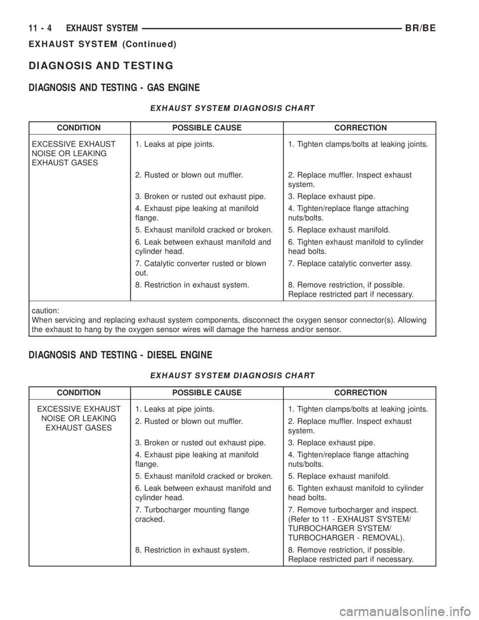
DIAGNOSIS AND TESTING
DIAGNOSIS AND TESTING - GAS ENGINE
EXHAUST SYSTEM DIAGNOSIS CHART
CONDITION POSSIBLE CAUSE CORRECTION
EXCESSIVE EXHAUST
NOISE OR LEAKING
EXHAUST GASES1. Leaks at pipe joints. 1. Tighten clamps/bolts at leaking joints.
2. Rusted or blown out muffler. 2. Replace muffler. Inspect exhaust
system.
3. Broken or rusted out exhaust pipe. 3. Replace exhaust pipe.
4. Exhaust pipe leaking at manifold
flange.4. Tighten/replace flange attaching
nuts/bolts.
5. Exhaust manifold cracked or broken. 5. Replace exhaust manifold.
6. Leak between exhaust manifold and
cylinder head.6. Tighten exhaust manifold to cylinder
head bolts.
7. Catalytic converter rusted or blown
out.7. Replace catalytic converter assy.
8. Restriction in exhaust system. 8. Remove restriction, if possible.
Replace restricted part if necessary.
caution:
When servicing and replacing exhaust system components, disconnect the oxygen sensor connector(s). Allowing
the exhaust to hang by the oxygen sensor wires will damage the harness and/or sensor.
DIAGNOSIS AND TESTING - DIESEL ENGINE
EXHAUST SYSTEM DIAGNOSIS CHART
CONDITION POSSIBLE CAUSE CORRECTION
EXCESSIVE EXHAUST
NOISE OR LEAKING
EXHAUST GASES1. Leaks at pipe joints. 1. Tighten clamps/bolts at leaking joints.
2. Rusted or blown out muffler. 2. Replace muffler. Inspect exhaust
system.
3. Broken or rusted out exhaust pipe. 3. Replace exhaust pipe.
4. Exhaust pipe leaking at manifold
flange.4. Tighten/replace flange attaching
nuts/bolts.
5. Exhaust manifold cracked or broken. 5. Replace exhaust manifold.
6. Leak between exhaust manifold and
cylinder head.6. Tighten exhaust manifold to cylinder
head bolts.
7. Turbocharger mounting flange
cracked.7. Remove turbocharger and inspect.
(Refer to 11 - EXHAUST SYSTEM/
TURBOCHARGER SYSTEM/
TURBOCHARGER - REMOVAL).
8. Restriction in exhaust system. 8. Remove restriction, if possible.
Replace restricted part if necessary.
11 - 4 EXHAUST SYSTEMBR/BE
EXHAUST SYSTEM (Continued)
Page 1300 of 2255
FUEL SYSTEM
TABLE OF CONTENTS
page page
FUEL DELIVERY - GASOLINE...............1
FUEL INJECTION - GASOLINE..............28FUEL DELIVERY - DIESEL.................54
FUEL INJECTION - DIESEL................91
FUEL DELIVERY - GASOLINE
TABLE OF CONTENTS
page page
FUEL DELIVERY - GASOLINE
DESCRIPTION - FUEL DELIVERY SYSTEM....2
OPERATION - FUEL DELIVERY SYSTEM......2
DIAGNOSIS AND TESTING - FUEL
PRESSURE LEAK DOWN TEST...........2
STANDARD PROCEDURE - FUEL SYSTEM
PRESSURE RELEASE...................3
SPECIFICATIONS
SPECIFICATIONS - FUEL SYSTEM
PRESSURE - GAS ENGINES..............3
SPECIFICATIONS - TORQUE - FUEL
DELIVERY............................4
SPECIAL TOOLS
FUEL SYSTEM........................4
FUEL FILTER/PRESSURE REGULATOR
DESCRIPTION..........................5
OPERATION............................5
REMOVAL.............................5
INSTALLATION..........................7
FUEL LEVEL SENDING UNIT / SENSOR
DESCRIPTION..........................7
OPERATION............................7
DIAGNOSIS AND TESTING - FUEL GAUGE
SENDING UNIT........................7
REMOVAL.............................7
INSTALLATION..........................8
FUEL LINES
DESCRIPTION..........................8
FUEL PUMP
DESCRIPTION..........................9
OPERATION............................9
DIAGNOSIS AND TESTING
DIAGNOSIS AND TESTING - FUEL PUMP
CAPACITY TEST.......................9
DIAGNOSIS AND TESTING - FUEL PUMP
PRESSURE TEST......................9DIAGNOSIS AND TESTING - FUEL PUMP
AMPERAGE TEST.....................10
FUEL PUMP MODULE
DESCRIPTION.........................12
OPERATION...........................13
REMOVAL.............................13
INSTALLATION.........................13
FUEL RAIL
DESCRIPTION
DESCRIPTION - 5.9L...................14
DESCRIPTION - 8.0L...................14
OPERATION
OPERATION - 5.9L....................14
OPERATION - 8.0L....................15
REMOVAL
REMOVAL - 5.9L......................15
REMOVAL - 8.0L......................16
INSTALLATION
INSTALLATION - 5.9L..................17
INSTALLATION - 8.0L..................18
FUEL TANK
DESCRIPTION.........................18
OPERATION...........................18
REMOVAL.............................18
INSTALLATION.........................20
FUEL TANK CHECK VALVE
DESCRIPTION.........................21
REMOVAL.............................22
INSTALLATION.........................23
INLET FILTER
REMOVAL.............................23
INSTALLATION.........................23
QUICK CONNECT FITTING
DESCRIPTION.........................24
STANDARD PROCEDURE - QUICK-CONNECT
FITTINGS...........................24
BR/BEFUEL SYSTEM 14 - 1
Page 1301 of 2255
FUEL DELIVERY - GASOLINE
DESCRIPTION - FUEL DELIVERY SYSTEM
The fuel delivery system consists of:
²the fuel pump module containing the electric
fuel pump, fuel filter/fuel pressure regulator, rollover
valve (certain modules), fuel gauge sending unit (fuel
level sensor) and a separate fuel filter located at bot-
tom of pump module
²fuel tubes/lines/hoses
²quick-connect fittings
²fuel injector rail
²fuel injectors
²fuel tank
²fuel tank filler/vent tube assembly
²fuel tank filler tube cap
²accelerator pedal
²throttle cable
OPERATION - FUEL DELIVERY SYSTEM
Fuel is returned through the fuel pump module
and back into the fuel tank through the fuel filter/
fuel pressure regulator. A separate fuel return line
from the engine to the tank is not used with any gas-
oline powered engine.
The fuel tank assembly consists of: the fuel tank,
fuel pump module assembly, fuel pump module lock-
nut/gasket and fuel tank check valve(s) (refer to 25,
Emission Control System for Fuel Tank Check Valve
information).
A fuel filler/vent tube assembly using a pressure/
vacuum, 1/4 turn fuel filler cap is used. The fuel
filler tube contains a flap door located below the fuel
fill cap.
Also to be considered part of the fuel system is the
evaporation control system. This is designed to
reduce the emission of fuel vapors into the atmo-
sphere. The description and function of the Evapora-
tive Control System is found in 25, Emission Control
Systems.
Both fuel filters (at bottom of fuel pump module
and within fuel pressure regulator) are designed for
extended service. They do not require normal sched-
uled maintenance. Filters should only be replaced if
a diagnostic procedure indicates to do so.
DIAGNOSIS AND TESTING - FUEL PRESSURE
LEAK DOWN TEST
Use this test in conjunction with the Fuel Pump
Pressure Test and Fuel Pump Capacity Test.
Check Valve Operation:The electric fuel pump
outlet contains a one-way check valve to prevent fuel
flow back into the tank and to maintain fuel supply
line pressure (engine warm) when pump is not oper-
ational. It is also used to keep the fuel supply linefull of gasoline when pump is not operational. After
the vehicle has cooled down, fuel pressure may drop
to 0 psi (cold fluid contracts), but liquid gasoline will
remain in fuel supply line between the check valve
and fuel injectors.Fuel pressure that has
dropped to 0 psi on a cooled down vehicle
(engine off) is a normal condition.When the elec-
tric fuel pump is activated, fuel pressure should
immediately(1±2 seconds) rise to specification.
Abnormally long periods of cranking to restart a
hotengine that has been shut down for a short
period of time may be caused by:
²Fuel pressure bleeding past a fuel injector(s).
²Fuel pressure bleeding past the check valve in
the fuel pump module.
(1) Disconnect the fuel inlet line at fuel rail. Refer
to Fuel Tubes/Lines/Hoses and Clamps for proce-
dures. On some engines, air cleaner housing removal
may be necessary before fuel line disconnection.
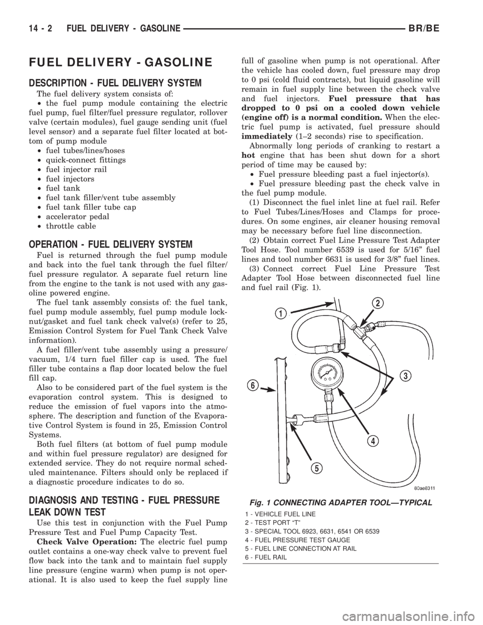
(2) Obtain correct Fuel Line Pressure Test Adapter
Tool Hose. Tool number 6539 is used for 5/16º fuel
lines and tool number 6631 is used for 3/8º fuel lines.
(3) Connect correct Fuel Line Pressure Test
Adapter Tool Hose between disconnected fuel line
and fuel rail (Fig. 1).
Fig. 1 CONNECTING ADAPTER TOOLÐTYPICAL
1 - VEHICLE FUEL LINE
2 - TEST PORT ªTº
3 - SPECIAL TOOL 6923, 6631, 6541 OR 6539
4 - FUEL PRESSURE TEST GAUGE
5 - FUEL LINE CONNECTION AT RAIL
6 - FUEL RAIL
14 - 2 FUEL DELIVERY - GASOLINEBR/BE
Page 1303 of 2255
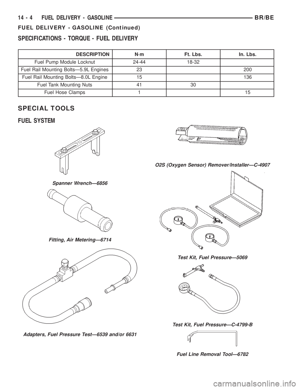
SPECIFICATIONS - TORQUE - FUEL DELIVERY
DESCRIPTION N´m Ft. Lbs. In. Lbs.
Fuel Pump Module Locknut 24-44 18-32
Fuel Rail Mounting BoltsÐ5.9L Engines 23 200
Fuel Rail Mounting BoltsÐ8.0L Engine 15 136
Fuel Tank Mounting Nuts 41 30
Fuel Hose Clamps 1 15
SPECIAL TOOLS
FUEL SYSTEM
Spanner WrenchÐ6856
Fitting, Air MeteringÐ6714
Adapters, Fuel Pressure TestÐ6539 and/or 6631
O2S (Oxygen Sensor) Remover/InstallerÐC-4907
Test Kit, Fuel PressureÐ5069
Test Kit, Fuel PressureÐC-4799-B
Fuel Line Removal ToolÐ6782
14 - 4 FUEL DELIVERY - GASOLINEBR/BE
FUEL DELIVERY - GASOLINE (Continued)
Page 1306 of 2255
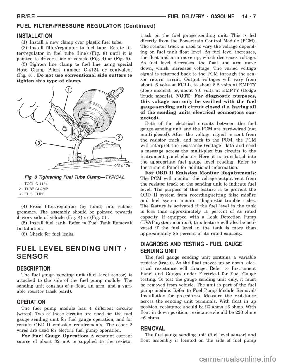
INSTALLATION
(1) Install a new clamp over plastic fuel tube.
(2) Install filter/regulator to fuel tube. Rotate fil-
ter/regulator in fuel tube (line) (Fig. 8) until it is
pointed to drivers side of vehicle (Fig. 4) or (Fig. 5).
(3) Tighten line clamp to fuel line using special
Hose Clamp Pliers number C-4124 or equivalent
(Fig. 8) .Do not use conventional side cutters to
tighten this type of clamp.
(4) Press filter/regulator (by hand) into rubber
grommet. The assembly should be pointed towards
drivers side of vehicle (Fig. 4) or (Fig. 5) .
(5) Install fuel tank. Refer to Fuel Tank Removal/
Installation.
(6) Check for fuel leaks.
FUEL LEVEL SENDING UNIT /
SENSOR
DESCRIPTION
The fuel gauge sending unit (fuel level sensor) is
attached to the side of the fuel pump module. The
sending unit consists of a float, an arm, and a vari-
able resistor track (card).
OPERATION
The fuel pump module has 4 different circuits
(wires). Two of these circuits are used for the fuel
gauge sending unit for fuel gauge operation, and for
certain OBD II emission requirements. The other 2
wires are used for electric fuel pump operation.
For Fuel Gauge Operation:A constant current
source of about 32 mA is supplied to the resistortrack on the fuel gauge sending unit. This is fed
directly from the Powertrain Control Module (PCM).
The resistor track is used to vary the voltage depend-
ing on fuel tank float level. As fuel level increases,
the float and arm move up, which decreases voltage.
As fuel level decreases, the float and arm move
down, which increases voltage. The varied voltage
signal is returned back to the PCM through the sen-
sor return circuit. Output voltages will vary from
about .6 volts at FULL, to about 8.6 volts at EMPTY
(Jeep models), or, about 7.0 volts at EMPTY (Dodge
Truck models).NOTE: For diagnostic purposes,
this voltage can only be verified with the fuel
gauge sending unit circuit closed (i.e. having all
of the sending units electrical connectors con-
nected).
Both of the electrical circuits between the fuel
gauge sending unit and the PCM are hard-wired (not
multi-plexed). After the voltage signal is sent from
the resistor track, and back to the PCM, the PCM
will interpret the resistance (voltage) data and send
a message across the multi-plex bus circuits to the
instrument panel cluster. Here it is translated into
the appropriate fuel gauge level reading. Refer to
Instrument Panel for additional information.
For OBD II Emission Monitor Requirements:
The PCM will monitor the voltage output sent from
the resistor track on the sending unit to indicate fuel
level. The purpose of this feature is to prevent the
OBD II system from recording/setting false misfire
and fuel system monitor diagnostic trouble codes.
The feature is activated if the fuel level in the tank
is less than approximately 15 percent of its rated
capacity. If equipped with a Leak Detection Pump
(EVAP system monitor), this feature will also be acti-
vated if the fuel level in the tank is more than
approximately 85 percent of its rated capacity.
DIAGNOSIS AND TESTING - FUEL GAUGE
SENDING UNIT
The fuel gauge sending unit contains a variable
resistor (track). As the float moves up or down, elec-
trical resistance will change. Refer to Instrument
Panel and Gauges under Electrical for Fuel Gauge
testing. To test the gauge sending unit only, it must
be removed from vehicle. The unit is part of the fuel
pump module. Refer to Fuel Pump Module Removal/
Installation for procedures. Measure the resistance
across the sending unit terminals. With float in up
position, resistance should be 20 ohms 6 ohms. With
float in down position, resistance should be 220 ohms
6 ohms.
REMOVAL
The fuel gauge sending unit (fuel level sensor) and
float assembly is located on the side of fuel pump
Fig. 8 Tightening Fuel Tube ClampÐTYPICAL
1 - TOOL C-4124
2 - TUBE CLAMP
3 - FUEL TUBE
BR/BEFUEL DELIVERY - GASOLINE 14 - 7
FUEL FILTER/PRESSURE REGULATOR (Continued)