sensor DODGE RAM 2002 Service Repair Manual
[x] Cancel search | Manufacturer: DODGE, Model Year: 2002, Model line: RAM, Model: DODGE RAM 2002Pages: 2255, PDF Size: 62.07 MB
Page 1307 of 2255
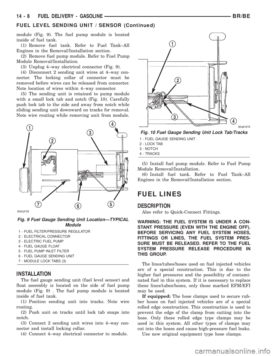
module (Fig. 9). The fuel pump module is located
inside of fuel tank.
(1) Remove fuel tank. Refer to Fuel Tank±All
Engines in the Removal/Installation section.
(2) Remove fuel pump module. Refer to Fuel Pump
Module Removal/Installation.
(3) Unplug 4±way electrical connector (Fig. 9).
(4) Disconnect 2 sending unit wires at 4±way con-
nector. The locking collar of connector must be
removed before wires can be released from connector.
Note location of wires within 4±way connector.
(5) The sending unit is retained to pump module
with a small lock tab and notch (Fig. 10). Carefully
push lock tab to the side and away from notch while
sliding sending unit downward on tracks for removal.
Note wire routing while removing unit from module.
INSTALLATION
The fuel gauge sending unit (fuel level sensor) and
float assembly is located on the side of fuel pump
module (Fig. 9) . The fuel pump module is located
inside of fuel tank.
(1) Position sending unit into tracks. Note wire
routing.
(2) Push unit on tracks until lock tab snaps into
notch.
(3) Connect 2 sending unit wires into 4±way con-
nector and install locking collar.
(4) Connect 4±way electrical connector to module.(5) Install fuel pump module. Refer to Fuel Pump
Module Removal/Installation.
(6) Install fuel tank. Refer to Fuel Tank±All
Engines in the Removal/Installation section.
FUEL LINES
DESCRIPTION
Also refer to Quick-Connect Fittings.
WARNING: THE FUEL SYSTEM IS UNDER A CON-
STANT PRESSURE (EVEN WITH THE ENGINE OFF).
BEFORE SERVICING ANY FUEL SYSTEM HOSES,
FITTINGS OR LINES, THE FUEL SYSTEM PRES-
SURE MUST BE RELEASED. REFER TO THE FUEL
SYSTEM PRESSURE RELEASE PROCEDURE IN
THIS GROUP.
The lines/tubes/hoses used on fuel injected vehicles
are of a special construction. This is due to the
higher fuel pressures and the possibility of contami-
nated fuel in this system. If it is necessary to replace
these lines/tubes/hoses, only those marked EFM/EFI
may be used.
If equipped:The hose clamps used to secure rub-
ber hoses on fuel injected vehicles are of a special
rolled edge construction. This construction is used to
prevent the edge of the clamp from cutting into the
hose. Only these rolled edge type clamps may be
used in this system. All other types of clamps may
cut into the hoses and cause high-pressure fuel leaks.
Use new original equipment type hose clamps.
Fig. 9 Fuel Gauge Sending Unit LocationÐTYPICAL
Module
1 - FUEL FILTER/PRESSURE REGULATOR
2 - ELECTRICAL CONNECTOR
3 - ELECTRIC FUEL PUMP
4 - FUEL GAUGE FLOAT
5 - FUEL PUMP INLET FILTER
6 - FUEL GAUGE SENDING UNIT
7 - MODULE LOCK TABS (3)
Fig. 10 Fuel Gauge Sending Unit Lock Tab/Tracks
1 - FUEL GAUGE SENDING UNIT
2 - LOCK TAB
3 - NOTCH
4 - TRACKS
14 - 8 FUEL DELIVERY - GASOLINEBR/BE
FUEL LEVEL SENDING UNIT / SENSOR (Continued)
Page 1311 of 2255
FUEL PUMP MODULE
DESCRIPTION
The fuel pump module on all gas powered engines
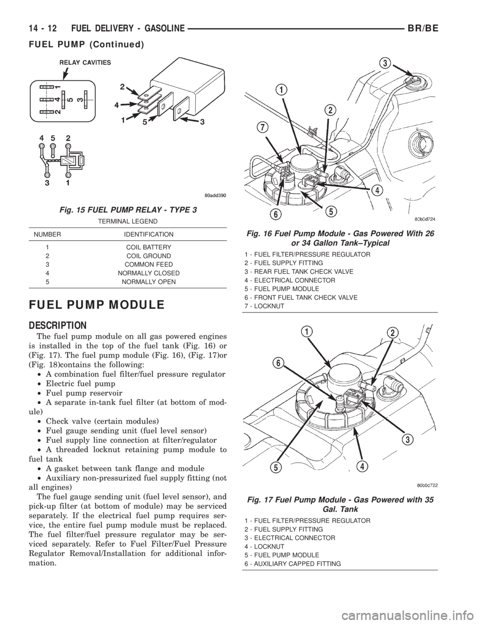
is installed in the top of the fuel tank (Fig. 16) or
(Fig. 17). The fuel pump module (Fig. 16), (Fig. 17)or
(Fig. 18)contains the following:
²A combination fuel filter/fuel pressure regulator
²Electric fuel pump
²Fuel pump reservoir
²A separate in-tank fuel filter (at bottom of mod-
ule)
²Check valve (certain modules)
²Fuel gauge sending unit (fuel level sensor)
²Fuel supply line connection at filter/regulator
²A threaded locknut retaining pump module to
fuel tank
²A gasket between tank flange and module
²Auxiliary non-pressurized fuel supply fitting (not
all engines)
The fuel gauge sending unit (fuel level sensor), and
pick-up filter (at bottom of module) may be serviced
separately. If the electrical fuel pump requires ser-
vice, the entire fuel pump module must be replaced.
The fuel filter/fuel pressure regulator may be ser-
viced separately. Refer to Fuel Filter/Fuel Pressure
Regulator Removal/Installation for additional infor-
mation.
Fig. 15 FUEL PUMP RELAY - TYPE 3
TERMINAL LEGEND
NUMBER IDENTIFICATION
1 COIL BATTERY
2 COIL GROUND
3 COMMON FEED
4 NORMALLY CLOSED
5 NORMALLY OPEN
Fig. 16 Fuel Pump Module - Gas Powered With 26
or 34 Gallon Tank±Typical
1 - FUEL FILTER/PRESSURE REGULATOR
2 - FUEL SUPPLY FITTING
3 - REAR FUEL TANK CHECK VALVE
4 - ELECTRICAL CONNECTOR
5 - FUEL PUMP MODULE
6 - FRONT FUEL TANK CHECK VALVE
7 - LOCKNUT
Fig. 17 Fuel Pump Module - Gas Powered with 35
Gal. Tank
1 - FUEL FILTER/PRESSURE REGULATOR
2 - FUEL SUPPLY FITTING
3 - ELECTRICAL CONNECTOR
4 - LOCKNUT
5 - FUEL PUMP MODULE
6 - AUXILIARY CAPPED FITTING
14 - 12 FUEL DELIVERY - GASOLINEBR/BE
FUEL PUMP (Continued)
Page 1317 of 2255
(5) Push therightfuel rail down until fuel injec-
tors have bottomed on injector shoulder. Push the
leftfuel rail down until fuel injectors have bottomed
on injector shoulder.
(6) Install fuel rail mounting bolts.
(7) Connect electrical connector to intake manifold
air temperature sensor.
(8) Connect electrical connectors at all fuel injec-
tors. To install connector, refer to (Fig. 26). Push con-
nector onto injector (1) and then push and lock red
colored slider (2). Verify connector is locked to injec-
tor by lightly tugging on connector.
(9) Install the A/C support bracket (if equipped).
(10) Install throttle body to intake manifold. Refer
to Throttle Body installation in this section of the
group.
(11) Install fuel tube (line) at side of fuel rail.
Refer to Quick-Connect Fittings for procedures.
(12) Install air cleaner.
(13) Connect battery cable to battery.
(14) Start engine and check for leaks.
INSTALLATION - 8.0L
(1) Apply a small amount of engine oil to each fuel
injector o-ring. This will help in fuel rail installation.
(2) Install injector(s) and injector clip(s) to fuel
rail.
NOTE: The fuel injector electrical connectors on all
10 injectors should be facing to the right (passen-
ger) side of the vehicle (Fig. 31).
(3) Position the fuel rail/fuel injector assembly to
the injector openings on the intake manifold.
(4) Guide each injector into the intake manifold.
Be careful not to tear the injector o-ring.
(5) Push therightfuel rail down until fuel injec-
tors have bottomed on injector shoulder. Push the
leftfuel rail down until fuel injectors have bottomed
on injector shoulder.
(6) Install the six fuel rail mounting bolts into the
lower half of intake manifold. Tighten bolts to 15
N´m (136 in. lbs.) torque.
(7) Connect electrical connectors at all fuel injec-
tors. To install connector, refer to (Fig. 30). Push con-
nector onto injector (1) and then push and lock red
colored slider (2). Verify connector is locked to injec-
tor by lightly tugging on connector. The injector wir-
ing harness is numerically tagged.
(8) Install upper half of intake manifold. Refer to
Engines for procedures.
(9) Connect main fuel line at fuel rail. Refer to
Quick-Connect Fittings for procedures.
(10) Install ignition coil pack and bracket assem-
bly at intake manifold and right engine valve cover
(four bolts).(11) Install throttle body to intake manifold. Refer
to Throttle Body removal in this group.
(12) Install throttle body linkage to throttle body.
(13) Install air cleaner tube and housing.
(14) Install negative battery cable at battery.
(15) Start engine and check for leaks.
FUEL TANK
DESCRIPTION
The fuel tank is constructed of a plastic material.
Its main functions are for fuel storage and for place-
ment of the fuel pump module.
OPERATION
All models pass a full 360 degree rollover test
without fuel leakage. To accomplish this, fuel and
vapor flow controls are required for all fuel tank con-
nections.
A fuel tank check valve(s) is mounted into the top
of the fuel tank (or pump module). Refer to Emission
Control System for fuel tank check valve information.
An evaporation control system is connected to the
rollover valve(s) to reduce emissions of fuel vapors
into the atmosphere. When fuel evaporates from the
fuel tank, vapors pass through vent hoses or tubes to
a charcoal canister where they are temporarily held.
When the engine is running, the vapors are drawn
into the intake manifold. Certain models are also
equipped with a self-diagnosing system using a Leak
Detection Pump (LDP). Refer to Emission Control
System for additional information.
REMOVAL
WARNING: GASOLINE POWERED ENGINES: THE
FUEL SYSTEM IS UNDER A CONSTANT PRESSURE
EVEN WITH THE ENGINE OFF. BEFORE SERVICING
THE FUEL TANK, FUEL SYSTEM PRESSURE MUST
BE RELEASED. REFER TO THE FUEL SYSTEM
PRESSURE RELEASE PROCEDURE BEFORE SER-
VICING THE FUEL TANK.
Two different procedures may be used to drain fuel
tank (lowering tank or using DRB scan tool). When
equipped with a diesel engine, the DRB scan tool
cannot be used (no electric fuel pump).
The quickest draining procedure involves lowering
the fuel tank.
Gasoline Powered Engines:As an alternative
procedure, the electric fuel pump may be activated
allowing tank to be drained at fuel rail connection.
Refer to DRB scan tool for fuel pump activation pro-
cedures. Before disconnecting fuel line at fuel rail,
release fuel pressure. Refer to the Fuel System Pres-
sure Release Procedure in this group for procedures.
14 - 18 FUEL DELIVERY - GASOLINEBR/BE
FUEL RAIL (Continued)
Page 1327 of 2255
FUEL INJECTION - GASOLINE
TABLE OF CONTENTS
page page
FUEL INJECTION - GASOLINE
DIAGNOSIS AND TESTING
VISUAL INSPECTIONÐ5.9L ENGINES.....29
VISUAL INSPECTIONÐ8.0L ENGINE......32
SPECIFICATIONS - TORQUE - GAS FUEL
INJECTION..........................35
SPECIAL TOOLS
FUEL SYSTEM.......................35
ACCELERATOR PEDAL
REMOVAL.............................36
INSTALLATION.........................37
CRANKSHAFT POSITION SENSOR
DESCRIPTION
DESCRIPTION - 5.9L...................37
DESCRIPTION - 8.0L...................37
OPERATION
OPERATION - 5.9L....................37
OPERATION - 8.0L....................38
REMOVAL
REMOVAL - 5.9L......................38
REMOVAL - 8.0L......................39
INSTALLATION
INSTALLATION - 5.9L..................39
INSTALLATION - 8.0L..................39
FUEL PUMP RELAY
DESCRIPTION.........................40
OPERATION...........................40
REMOVAL.............................40
INSTALLATION.........................40
IDLE AIR CONTROL MOTOR
DESCRIPTION.........................40
OPERATION...........................40
REMOVAL
REMOVAL - 5.9L......................41
REMOVAL - 8.0L......................41
INSTALLATION
INSTALLATION - 5.9L..................42
INSTALLATION - 8.0L..................42
INTAKE AIR TEMPERATURE SENSOR
DESCRIPTION - 5.9L/8.0L.................42
OPERATION - 5.9L/8.0L..................42
REMOVAL
REMOVAL - 5.9L......................42
REMOVAL - 8.0L......................43
INSTALLATION
INSTALLATION - 5.9L..................43
INSTALLATION - 8.0L..................43MANIFOLD ABSOLUTE PRESSURE SENSOR
DESCRIPTION - 5.9L/8.0L.................43
OPERATION - 5.9L/8.0L..................43
REMOVAL
REMOVAL - 5.9L......................44
REMOVAL - 8.0L......................44
INSTALLATION
INSTALLATION - 5.9L..................45
INSTALLATION - 8.0L..................45
O2 SENSOR
DESCRIPTION.........................45
OPERATION...........................45
REMOVAL.............................46
INSTALLATION.........................47
PTO SWITCH
DESCRIPTION.........................47
OPERATION...........................47
THROTTLE BODY
DESCRIPTION.........................47
OPERATION...........................47
REMOVAL
REMOVAL - 5.9L......................47
REMOVAL - 8.0L......................47
INSTALLATION
INSTALLATION - 5.9L..................48
INSTALLATION - 8.0L..................49
THROTTLE CONTROL CABLE
REMOVAL.............................49
INSTALLATION.........................50
THROTTLE POSITION SENSOR
DESCRIPTION.........................50
OPERATION...........................50
REMOVAL
REMOVAL - 5.9L......................50
REMOVAL - 8.0L......................50
INSTALLATION
INSTALLATION - 5.9L..................51
INSTALLATION - 8.0L..................51
FUEL INJECTOR
DESCRIPTION.........................52
OPERATION
OPERATION.........................52
OPERATION - PCM OUTPUT............52
DIAGNOSIS AND TESTING - FUEL INJECTOR . 53
REMOVAL.............................53
INSTALLATION.........................53
14 - 28 FUEL INJECTION - GASOLINEBR/BE
Page 1328 of 2255
FUEL INJECTION - GASOLINE
DIAGNOSIS AND TESTING
VISUAL INSPECTIONÐ5.9L ENGINES
A visual inspection for loose, disconnected or incor-
rectly routed wires and hoses should be made. This
should be done before attempting to diagnose or ser-
vice the fuel injection system. A visual check will
help spot these faults and save unnecessary test and
diagnostic time. A thorough visual inspection will
include the following checks:
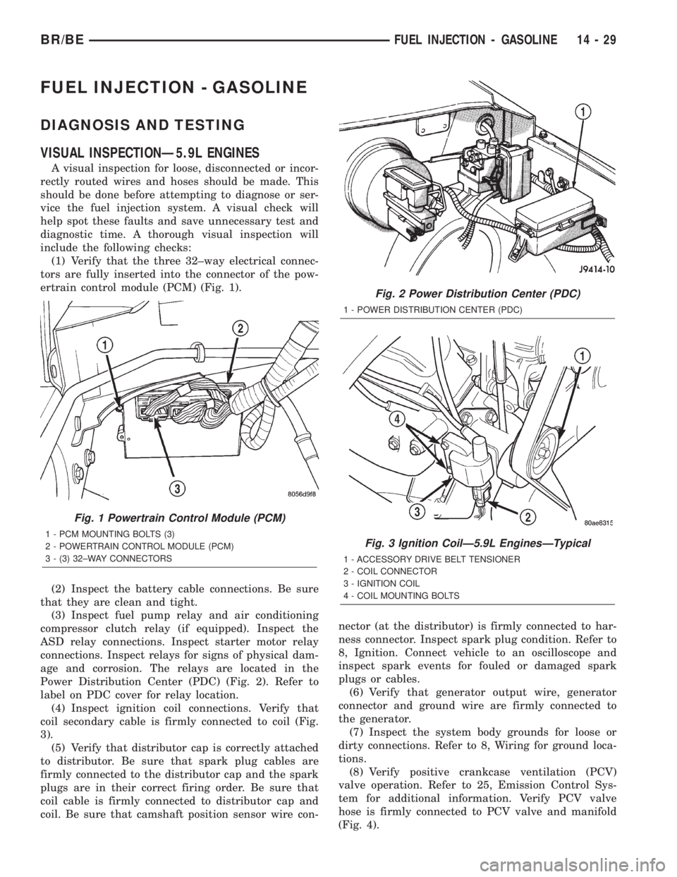
(1) Verify that the three 32±way electrical connec-
tors are fully inserted into the connector of the pow-
ertrain control module (PCM) (Fig. 1).
(2) Inspect the battery cable connections. Be sure
that they are clean and tight.
(3) Inspect fuel pump relay and air conditioning
compressor clutch relay (if equipped). Inspect the
ASD relay connections. Inspect starter motor relay
connections. Inspect relays for signs of physical dam-
age and corrosion. The relays are located in the
Power Distribution Center (PDC) (Fig. 2). Refer to
label on PDC cover for relay location.
(4) Inspect ignition coil connections. Verify that
coil secondary cable is firmly connected to coil (Fig.
3).
(5) Verify that distributor cap is correctly attached
to distributor. Be sure that spark plug cables are
firmly connected to the distributor cap and the spark
plugs are in their correct firing order. Be sure that
coil cable is firmly connected to distributor cap and
coil. Be sure that camshaft position sensor wire con-nector (at the distributor) is firmly connected to har-
ness connector. Inspect spark plug condition. Refer to
8, Ignition. Connect vehicle to an oscilloscope and
inspect spark events for fouled or damaged spark
plugs or cables.
(6) Verify that generator output wire, generator
connector and ground wire are firmly connected to
the generator.
(7) Inspect the system body grounds for loose or
dirty connections. Refer to 8, Wiring for ground loca-
tions.
(8) Verify positive crankcase ventilation (PCV)
valve operation. Refer to 25, Emission Control Sys-
tem for additional information. Verify PCV valve
hose is firmly connected to PCV valve and manifold
(Fig. 4).
Fig. 1 Powertrain Control Module (PCM)
1 - PCM MOUNTING BOLTS (3)
2 - POWERTRAIN CONTROL MODULE (PCM)
3 - (3) 32±WAY CONNECTORS
Fig. 2 Power Distribution Center (PDC)
1 - POWER DISTRIBUTION CENTER (PDC)
Fig. 3 Ignition CoilÐ5.9L EnginesÐTypical
1 - ACCESSORY DRIVE BELT TENSIONER
2 - COIL CONNECTOR
3 - IGNITION COIL
4 - COIL MOUNTING BOLTS
BR/BEFUEL INJECTION - GASOLINE 14 - 29
Page 1329 of 2255
(9) Inspect fuel tube quick-connect fitting-to-fuel
rail connections.
(10) Verify that hose connections to all ports of
vacuum fittings on intake manifold are tight and not
leaking.
(11) Inspect accelerator cable, transmission throt-
tle cable (if equipped) and cruise control cable con-
nections (if equipped). Check their connections to the
throttle arm of throttle body for any binding or
restrictions.
(12) If equipped with vacuum brake booster, verify
that vacuum booster hose is firmly connected to fit-
ting on intake manifold. Also check connection to
brake vacuum booster.
(13) Inspect the air cleaner inlet and air cleaner
element for dirt or restrictions.
(14) Inspect radiator grille area, radiator fins and
air conditioning condenser for restrictions.
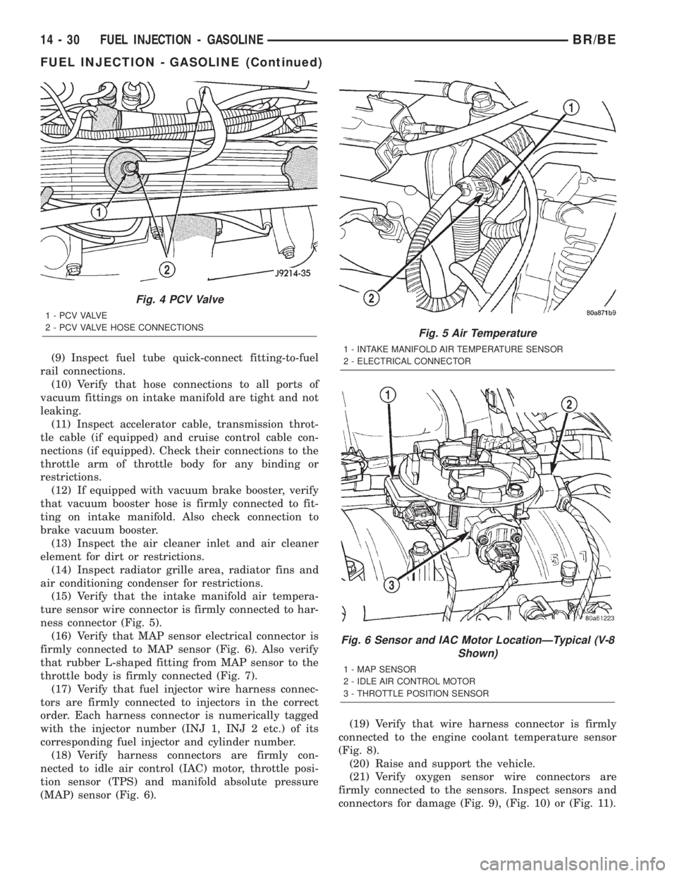
(15) Verify that the intake manifold air tempera-
ture sensor wire connector is firmly connected to har-
ness connector (Fig. 5).
(16) Verify that MAP sensor electrical connector is
firmly connected to MAP sensor (Fig. 6). Also verify
that rubber L-shaped fitting from MAP sensor to the
throttle body is firmly connected (Fig. 7).
(17) Verify that fuel injector wire harness connec-
tors are firmly connected to injectors in the correct
order. Each harness connector is numerically tagged
with the injector number (INJ 1, INJ 2 etc.) of its
corresponding fuel injector and cylinder number.
(18) Verify harness connectors are firmly con-
nected to idle air control (IAC) motor, throttle posi-
tion sensor (TPS) and manifold absolute pressure
(MAP) sensor (Fig. 6).(19) Verify that wire harness connector is firmly
connected to the engine coolant temperature sensor
(Fig. 8).
(20) Raise and support the vehicle.
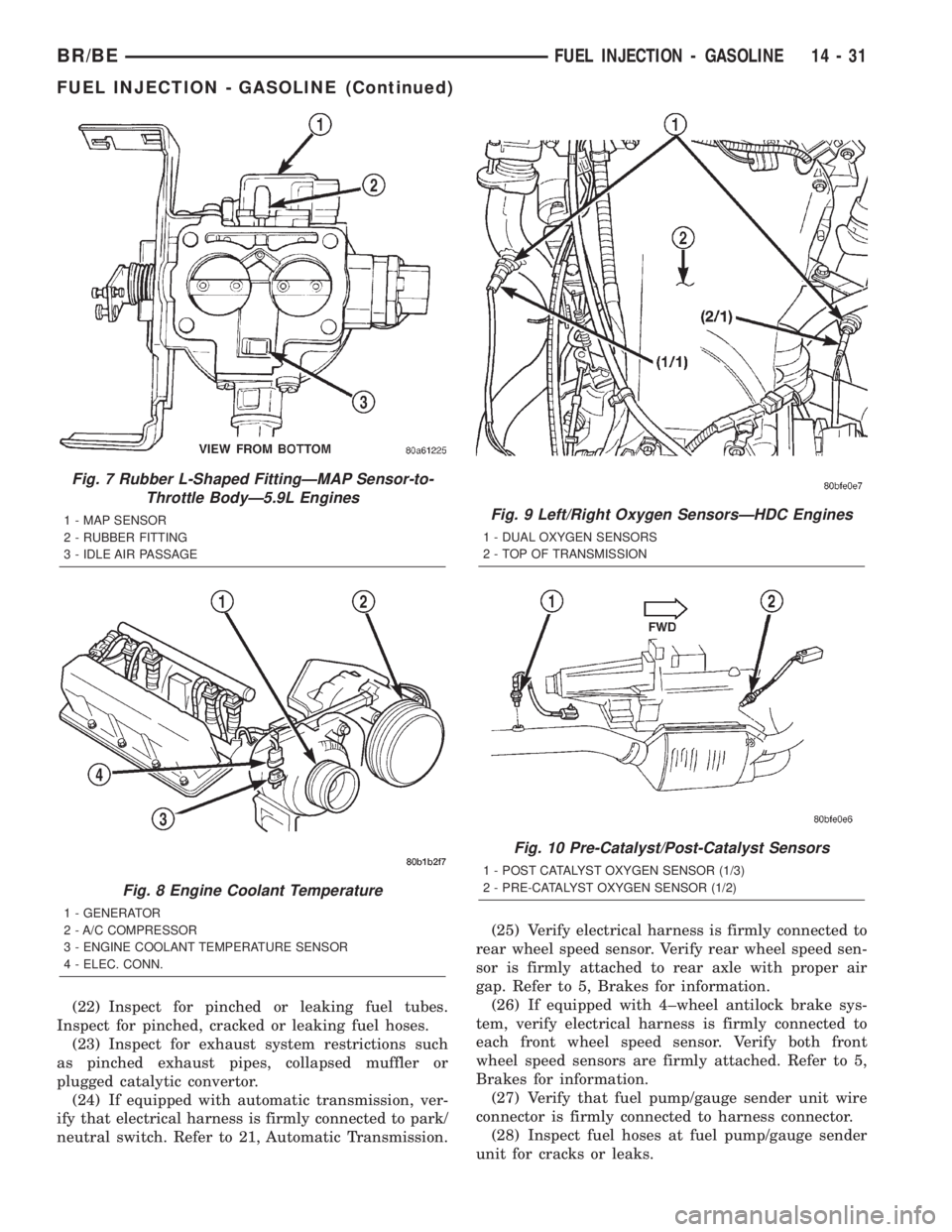
(21) Verify oxygen sensor wire connectors are
firmly connected to the sensors. Inspect sensors and
connectors for damage (Fig. 9), (Fig. 10) or (Fig. 11).
Fig. 4 PCV Valve
1 - P C V VA LV E
2 - PCV VALVE HOSE CONNECTIONS
Fig. 5 Air Temperature
1 - INTAKE MANIFOLD AIR TEMPERATURE SENSOR
2 - ELECTRICAL CONNECTOR
Fig. 6 Sensor and IAC Motor LocationÐTypical (V-8
Shown)
1 - MAP SENSOR
2 - IDLE AIR CONTROL MOTOR
3 - THROTTLE POSITION SENSOR
14 - 30 FUEL INJECTION - GASOLINEBR/BE
FUEL INJECTION - GASOLINE (Continued)
Page 1330 of 2255
(22) Inspect for pinched or leaking fuel tubes.
Inspect for pinched, cracked or leaking fuel hoses.
(23) Inspect for exhaust system restrictions such
as pinched exhaust pipes, collapsed muffler or
plugged catalytic convertor.
(24) If equipped with automatic transmission, ver-
ify that electrical harness is firmly connected to park/
neutral switch. Refer to 21, Automatic Transmission.(25) Verify electrical harness is firmly connected to
rear wheel speed sensor. Verify rear wheel speed sen-
sor is firmly attached to rear axle with proper air
gap. Refer to 5, Brakes for information.
(26) If equipped with 4±wheel antilock brake sys-
tem, verify electrical harness is firmly connected to
each front wheel speed sensor. Verify both front
wheel speed sensors are firmly attached. Refer to 5,
Brakes for information.
(27) Verify that fuel pump/gauge sender unit wire
connector is firmly connected to harness connector.
(28) Inspect fuel hoses at fuel pump/gauge sender
unit for cracks or leaks.
Fig. 7 Rubber L-Shaped FittingÐMAP Sensor-to-
Throttle BodyÐ5.9L Engines
1 - MAP SENSOR
2 - RUBBER FITTING
3 - IDLE AIR PASSAGE
Fig. 8 Engine Coolant Temperature
1 - GENERATOR
2 - A/C COMPRESSOR
3 - ENGINE COOLANT TEMPERATURE SENSOR
4 - ELEC. CONN.
Fig. 9 Left/Right Oxygen SensorsÐHDC Engines
1 - DUAL OXYGEN SENSORS
2 - TOP OF TRANSMISSION
Fig. 10 Pre-Catalyst/Post-Catalyst Sensors
1 - POST CATALYST OXYGEN SENSOR (1/3)
2 - PRE-CATALYST OXYGEN SENSOR (1/2)
BR/BEFUEL INJECTION - GASOLINE 14 - 31
FUEL INJECTION - GASOLINE (Continued)
Page 1331 of 2255
(29) Inspect transmission torque convertor housing
(automatic transmission) or clutch housing (manual
transmission) for damage to timing ring on drive
plate/flywheel.
(30) Verify that battery cable and solenoid feed
wire connections to the starter solenoid are tight and
clean. Inspect for chaffed wires or wires rubbing up
against other components.
VISUAL INSPECTIONÐ8.0L ENGINE
A visual inspection for loose, disconnected or incor-
rectly routed wires and hoses should be made. This
should be done before attempting to diagnose or ser-
vice the fuel injection system. A visual check will
help spot these faults and save unnecessary test and
diagnostic time. A thorough visual inspection will
include the following checks:
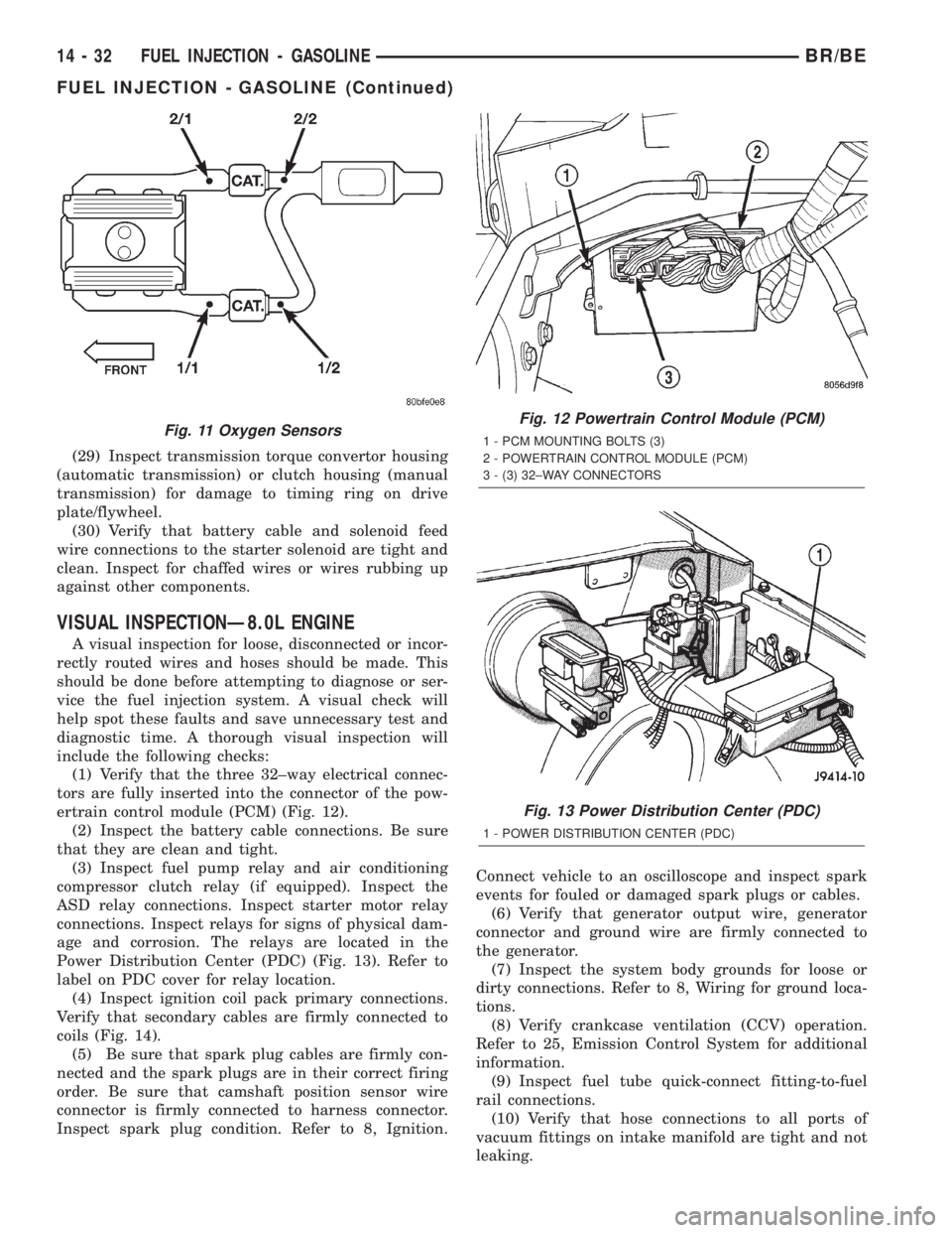
(1) Verify that the three 32±way electrical connec-
tors are fully inserted into the connector of the pow-
ertrain control module (PCM) (Fig. 12).
(2) Inspect the battery cable connections. Be sure
that they are clean and tight.
(3) Inspect fuel pump relay and air conditioning
compressor clutch relay (if equipped). Inspect the
ASD relay connections. Inspect starter motor relay
connections. Inspect relays for signs of physical dam-
age and corrosion. The relays are located in the
Power Distribution Center (PDC) (Fig. 13). Refer to
label on PDC cover for relay location.
(4) Inspect ignition coil pack primary connections.
Verify that secondary cables are firmly connected to
coils (Fig. 14).
(5) Be sure that spark plug cables are firmly con-
nected and the spark plugs are in their correct firing
order. Be sure that camshaft position sensor wire
connector is firmly connected to harness connector.
Inspect spark plug condition. Refer to 8, Ignition.Connect vehicle to an oscilloscope and inspect spark
events for fouled or damaged spark plugs or cables.
(6) Verify that generator output wire, generator
connector and ground wire are firmly connected to
the generator.
(7) Inspect the system body grounds for loose or
dirty connections. Refer to 8, Wiring for ground loca-
tions.
(8) Verify crankcase ventilation (CCV) operation.
Refer to 25, Emission Control System for additional
information.
(9) Inspect fuel tube quick-connect fitting-to-fuel
rail connections.
(10) Verify that hose connections to all ports of
vacuum fittings on intake manifold are tight and not
leaking.
Fig. 11 Oxygen SensorsFig. 12 Powertrain Control Module (PCM)
1 - PCM MOUNTING BOLTS (3)
2 - POWERTRAIN CONTROL MODULE (PCM)
3 - (3) 32±WAY CONNECTORS
Fig. 13 Power Distribution Center (PDC)
1 - POWER DISTRIBUTION CENTER (PDC)
14 - 32 FUEL INJECTION - GASOLINEBR/BE
FUEL INJECTION - GASOLINE (Continued)
Page 1332 of 2255
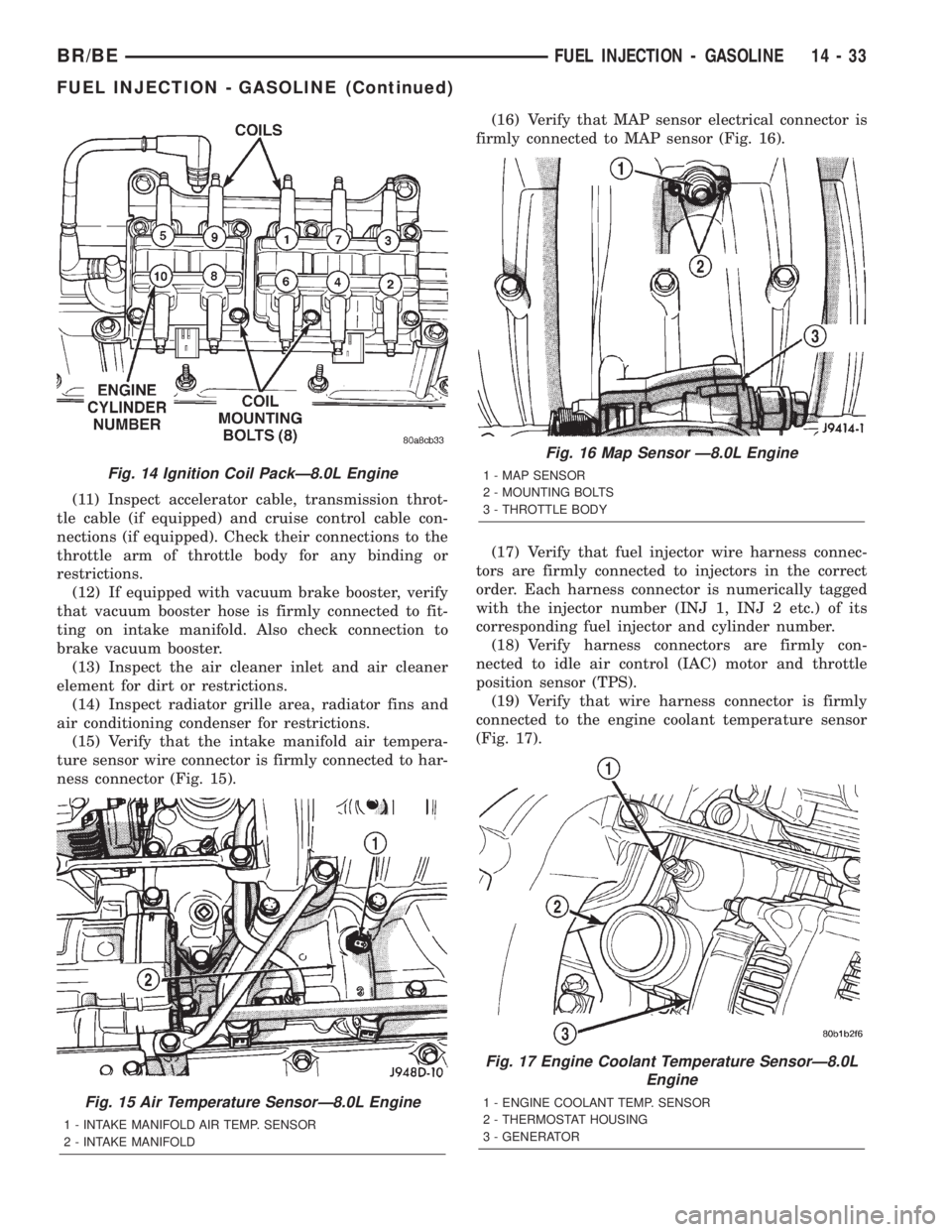
(11) Inspect accelerator cable, transmission throt-
tle cable (if equipped) and cruise control cable con-
nections (if equipped). Check their connections to the
throttle arm of throttle body for any binding or
restrictions.
(12) If equipped with vacuum brake booster, verify
that vacuum booster hose is firmly connected to fit-
ting on intake manifold. Also check connection to
brake vacuum booster.
(13) Inspect the air cleaner inlet and air cleaner
element for dirt or restrictions.
(14) Inspect radiator grille area, radiator fins and
air conditioning condenser for restrictions.
(15) Verify that the intake manifold air tempera-
ture sensor wire connector is firmly connected to har-
ness connector (Fig. 15).(16) Verify that MAP sensor electrical connector is
firmly connected to MAP sensor (Fig. 16).
(17) Verify that fuel injector wire harness connec-
tors are firmly connected to injectors in the correct
order. Each harness connector is numerically tagged
with the injector number (INJ 1, INJ 2 etc.) of its
corresponding fuel injector and cylinder number.
(18) Verify harness connectors are firmly con-
nected to idle air control (IAC) motor and throttle
position sensor (TPS).
(19) Verify that wire harness connector is firmly
connected to the engine coolant temperature sensor
(Fig. 17).
Fig. 14 Ignition Coil PackÐ8.0L Engine
Fig. 15 Air Temperature SensorÐ8.0L Engine
1 - INTAKE MANIFOLD AIR TEMP. SENSOR
2 - INTAKE MANIFOLD
Fig. 16 Map Sensor Ð8.0L Engine
1 - MAP SENSOR
2 - MOUNTING BOLTS
3 - THROTTLE BODY
Fig. 17 Engine Coolant Temperature SensorÐ8.0L
Engine
1 - ENGINE COOLANT TEMP. SENSOR
2 - THERMOSTAT HOUSING
3 - GENERATOR
BR/BEFUEL INJECTION - GASOLINE 14 - 33
FUEL INJECTION - GASOLINE (Continued)
Page 1333 of 2255
(20) Raise and support the vehicle.
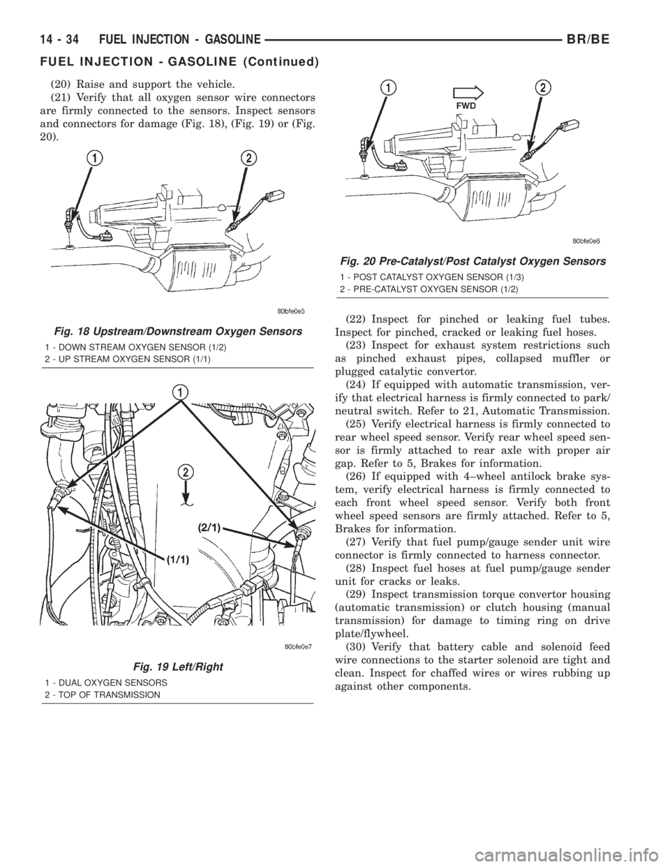
(21) Verify that all oxygen sensor wire connectors
are firmly connected to the sensors. Inspect sensors
and connectors for damage (Fig. 18), (Fig. 19) or (Fig.
20).
(22) Inspect for pinched or leaking fuel tubes.
Inspect for pinched, cracked or leaking fuel hoses.
(23) Inspect for exhaust system restrictions such
as pinched exhaust pipes, collapsed muffler or
plugged catalytic convertor.
(24) If equipped with automatic transmission, ver-
ify that electrical harness is firmly connected to park/
neutral switch. Refer to 21, Automatic Transmission.
(25) Verify electrical harness is firmly connected to
rear wheel speed sensor. Verify rear wheel speed sen-
sor is firmly attached to rear axle with proper air
gap. Refer to 5, Brakes for information.
(26) If equipped with 4±wheel antilock brake sys-
tem, verify electrical harness is firmly connected to
each front wheel speed sensor. Verify both front
wheel speed sensors are firmly attached. Refer to 5,
Brakes for information.
(27) Verify that fuel pump/gauge sender unit wire
connector is firmly connected to harness connector.
(28) Inspect fuel hoses at fuel pump/gauge sender
unit for cracks or leaks.
(29) Inspect transmission torque convertor housing
(automatic transmission) or clutch housing (manual
transmission) for damage to timing ring on drive
plate/flywheel.
(30) Verify that battery cable and solenoid feed
wire connections to the starter solenoid are tight and
clean. Inspect for chaffed wires or wires rubbing up
against other components.
Fig. 18 Upstream/Downstream Oxygen Sensors
1 - DOWN STREAM OXYGEN SENSOR (1/2)
2 - UP STREAM OXYGEN SENSOR (1/1)
Fig. 19 Left/Right
1 - DUAL OXYGEN SENSORS
2 - TOP OF TRANSMISSION
Fig. 20 Pre-Catalyst/Post Catalyst Oxygen Sensors
1 - POST CATALYST OXYGEN SENSOR (1/3)
2 - PRE-CATALYST OXYGEN SENSOR (1/2)
14 - 34 FUEL INJECTION - GASOLINEBR/BE
FUEL INJECTION - GASOLINE (Continued)