DODGE RAM 2002 Service Repair Manual
Manufacturer: DODGE, Model Year: 2002, Model line: RAM, Model: DODGE RAM 2002Pages: 2255, PDF Size: 62.07 MB
Page 1701 of 2255
ASSEMBLY
CAUTION: Do not force valves or plugs into place
during reassembly. If the valve body bores, valves
and plugs are free of distortion or burrs, the valve
body components should all slide into place easily.
In addition, do not overtighten the transfer plate
and valve body screws during reassembly. Over-
tightening can distort the housings resulting in
valve sticking, cross leakage and unsatisfactory
operation. Tighten valve body screws to recom-
mended torque only.
LOWER HOUSING
(1) Lubricate valves, springs, and the housing
valve and plug bores with clean transmission fluid
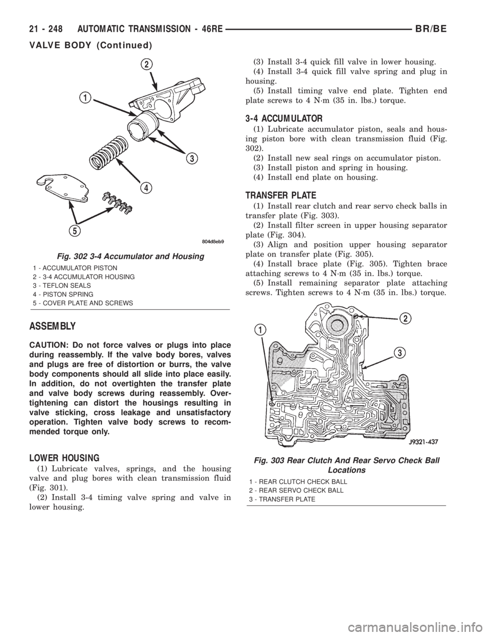
(Fig. 301).
(2) Install 3-4 timing valve spring and valve in
lower housing.(3) Install 3-4 quick fill valve in lower housing.
(4) Install 3-4 quick fill valve spring and plug in
housing.
(5) Install timing valve end plate. Tighten end
plate screws to 4 N´m (35 in. lbs.) torque.
3-4 ACCUMULATOR
(1) Lubricate accumulator piston, seals and hous-
ing piston bore with clean transmission fluid (Fig.
302).
(2) Install new seal rings on accumulator piston.
(3) Install piston and spring in housing.
(4) Install end plate on housing.
TRANSFER PLATE
(1) Install rear clutch and rear servo check balls in
transfer plate (Fig. 303).
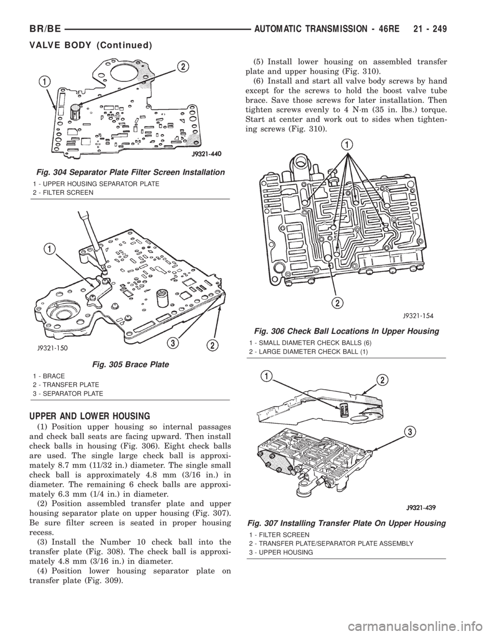
(2) Install filter screen in upper housing separator
plate (Fig. 304).
(3) Align and position upper housing separator
plate on transfer plate (Fig. 305).
(4) Install brace plate (Fig. 305). Tighten brace
attaching screws to 4 N´m (35 in. lbs.) torque.
(5) Install remaining separator plate attaching
screws. Tighten screws to 4 N´m (35 in. lbs.) torque.
Fig. 302 3-4 Accumulator and Housing
1 - ACCUMULATOR PISTON
2 - 3-4 ACCUMULATOR HOUSING
3 - TEFLON SEALS
4 - PISTON SPRING
5 - COVER PLATE AND SCREWS
Fig. 303 Rear Clutch And Rear Servo Check Ball
Locations
1 - REAR CLUTCH CHECK BALL
2 - REAR SERVO CHECK BALL
3 - TRANSFER PLATE
21 - 248 AUTOMATIC TRANSMISSION - 46REBR/BE
VALVE BODY (Continued)
Page 1702 of 2255
UPPER AND LOWER HOUSING
(1) Position upper housing so internal passages
and check ball seats are facing upward. Then install
check balls in housing (Fig. 306). Eight check balls
are used. The single large check ball is approxi-
mately 8.7 mm (11/32 in.) diameter. The single small
check ball is approximately 4.8 mm (3/16 in.) in
diameter. The remaining 6 check balls are approxi-
mately 6.3 mm (1/4 in.) in diameter.
(2) Position assembled transfer plate and upper
housing separator plate on upper housing (Fig. 307).
Be sure filter screen is seated in proper housing
recess.
(3) Install the Number 10 check ball into the
transfer plate (Fig. 308). The check ball is approxi-
mately 4.8 mm (3/16 in.) in diameter.
(4) Position lower housing separator plate on
transfer plate (Fig. 309).(5) Install lower housing on assembled transfer
plate and upper housing (Fig. 310).
(6) Install and start all valve body screws by hand
except for the screws to hold the boost valve tube
brace. Save those screws for later installation. Then
tighten screws evenly to 4 N´m (35 in. lbs.) torque.
Start at center and work out to sides when tighten-
ing screws (Fig. 310).
Fig. 304 Separator Plate Filter Screen Installation
1 - UPPER HOUSING SEPARATOR PLATE
2 - FILTER SCREEN
Fig. 305 Brace Plate
1 - BRACE
2 - TRANSFER PLATE
3 - SEPARATOR PLATE
Fig. 306 Check Ball Locations In Upper Housing
1 - SMALL DIAMETER CHECK BALLS (6)
2 - LARGE DIAMETER CHECK BALL (1)
Fig. 307 Installing Transfer Plate On Upper Housing
1 - FILTER SCREEN
2 - TRANSFER PLATE/SEPARATOR PLATE ASSEMBLY
3 - UPPER HOUSING
BR/BEAUTOMATIC TRANSMISSION - 46RE 21 - 249
VALVE BODY (Continued)
Page 1703 of 2255
UPPER HOUSING VALVE AND PLUG
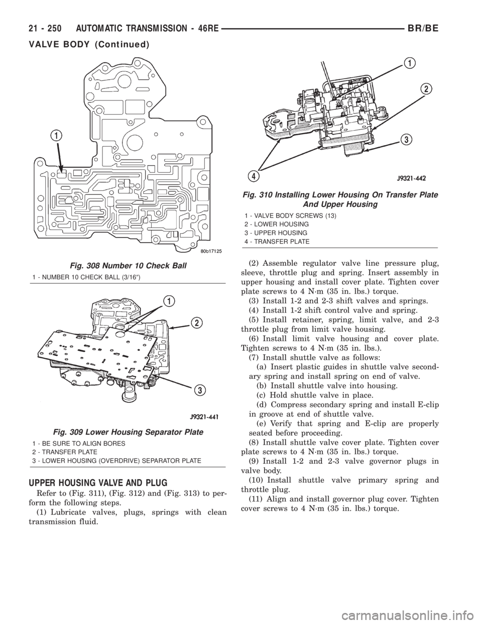
Refer to (Fig. 311), (Fig. 312) and (Fig. 313) to per-
form the following steps.
(1) Lubricate valves, plugs, springs with clean
transmission fluid.(2) Assemble regulator valve line pressure plug,
sleeve, throttle plug and spring. Insert assembly in
upper housing and install cover plate. Tighten cover
plate screws to 4 N´m (35 in. lbs.) torque.
(3) Install 1-2 and 2-3 shift valves and springs.
(4) Install 1-2 shift control valve and spring.
(5) Install retainer, spring, limit valve, and 2-3
throttle plug from limit valve housing.
(6) Install limit valve housing and cover plate.
Tighten screws to 4 N´m (35 in. lbs.).
(7) Install shuttle valve as follows:
(a) Insert plastic guides in shuttle valve second-
ary spring and install spring on end of valve.
(b) Install shuttle valve into housing.
(c) Hold shuttle valve in place.
(d) Compress secondary spring and install E-clip
in groove at end of shuttle valve.
(e) Verify that spring and E-clip are properly
seated before proceeding.
(8) Install shuttle valve cover plate. Tighten cover
plate screws to 4 N´m (35 in. lbs.) torque.
(9) Install 1-2 and 2-3 valve governor plugs in
valve body.
(10) Install shuttle valve primary spring and
throttle plug.
(11) Align and install governor plug cover. Tighten
cover screws to 4 N´m (35 in. lbs.) torque.
Fig. 308 Number 10 Check Ball
1 - NUMBER 10 CHECK BALL (3/169)
Fig. 309 Lower Housing Separator Plate
1 - BE SURE TO ALIGN BORES
2 - TRANSFER PLATE
3 - LOWER HOUSING (OVERDRIVE) SEPARATOR PLATE
Fig. 310 Installing Lower Housing On Transfer Plate
And Upper Housing
1 - VALVE BODY SCREWS (13)
2 - LOWER HOUSING
3 - UPPER HOUSING
4 - TRANSFER PLATE
21 - 250 AUTOMATIC TRANSMISSION - 46REBR/BE
VALVE BODY (Continued)
Page 1704 of 2255
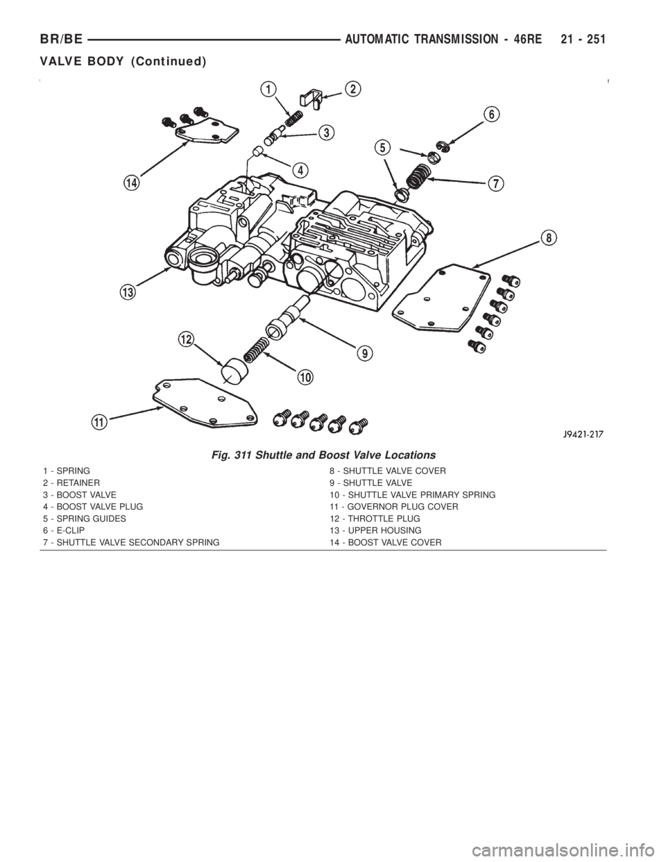
Fig. 311 Shuttle and Boost Valve Locations
1 - SPRING 8 - SHUTTLE VALVE COVER
2 - RETAINER 9 - SHUTTLE VALVE
3 - BOOST VALVE 10 - SHUTTLE VALVE PRIMARY SPRING
4 - BOOST VALVE PLUG 11 - GOVERNOR PLUG COVER
5 - SPRING GUIDES 12 - THROTTLE PLUG
6 - E-CLIP 13 - UPPER HOUSING
7 - SHUTTLE VALVE SECONDARY SPRING 14 - BOOST VALVE COVER
BR/BEAUTOMATIC TRANSMISSION - 46RE 21 - 251
VALVE BODY (Continued)
Page 1705 of 2255
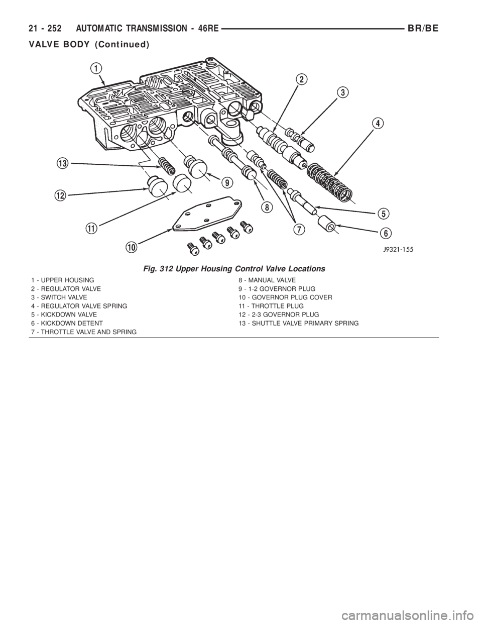
Fig. 312 Upper Housing Control Valve Locations
1 - UPPER HOUSING 8 - MANUAL VALVE
2 - REGULATOR VALVE 9 - 1-2 GOVERNOR PLUG
3 - SWITCH VALVE 10 - GOVERNOR PLUG COVER
4 - REGULATOR VALVE SPRING 11 - THROTTLE PLUG
5 - KICKDOWN VALVE 12 - 2-3 GOVERNOR PLUG
6 - KICKDOWN DETENT 13 - SHUTTLE VALVE PRIMARY SPRING
7 - THROTTLE VALVE AND SPRING
21 - 252 AUTOMATIC TRANSMISSION - 46REBR/BE
VALVE BODY (Continued)
Page 1706 of 2255
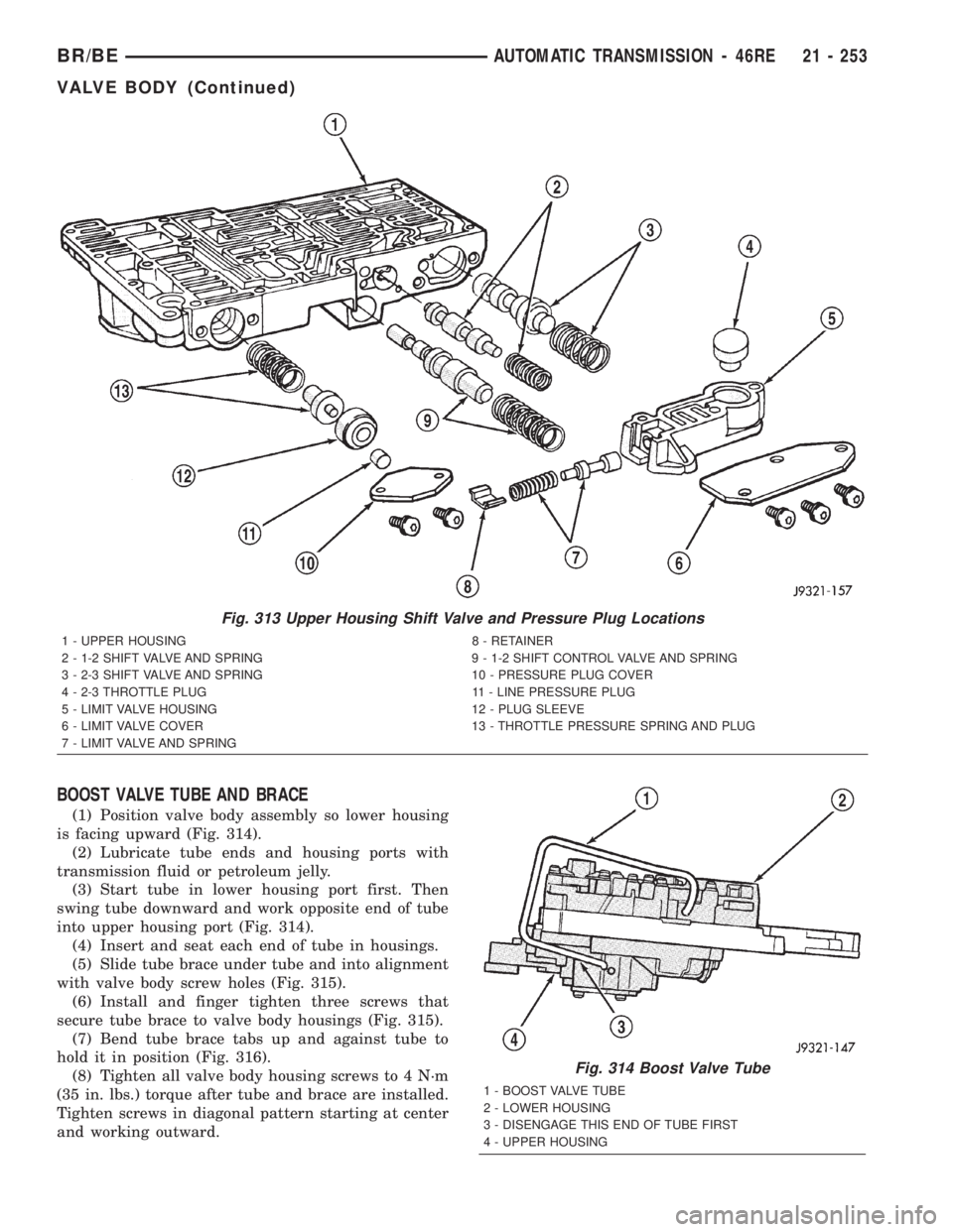
BOOST VALVE TUBE AND BRACE
(1) Position valve body assembly so lower housing
is facing upward (Fig. 314).
(2) Lubricate tube ends and housing ports with
transmission fluid or petroleum jelly.
(3) Start tube in lower housing port first. Then
swing tube downward and work opposite end of tube
into upper housing port (Fig. 314).
(4) Insert and seat each end of tube in housings.
(5) Slide tube brace under tube and into alignment
with valve body screw holes (Fig. 315).
(6) Install and finger tighten three screws that
secure tube brace to valve body housings (Fig. 315).
(7) Bend tube brace tabs up and against tube to
hold it in position (Fig. 316).
(8) Tighten all valve body housing screws to 4 N´m
(35 in. lbs.) torque after tube and brace are installed.
Tighten screws in diagonal pattern starting at center
and working outward.
Fig. 313 Upper Housing Shift Valve and Pressure Plug Locations
1 - UPPER HOUSING 8 - RETAINER
2 - 1-2 SHIFT VALVE AND SPRING 9 - 1-2 SHIFT CONTROL VALVE AND SPRING
3 - 2-3 SHIFT VALVE AND SPRING 10 - PRESSURE PLUG COVER
4 - 2-3 THROTTLE PLUG 11 - LINE PRESSURE PLUG
5 - LIMIT VALVE HOUSING 12 - PLUG SLEEVE
6 - LIMIT VALVE COVER 13 - THROTTLE PRESSURE SPRING AND PLUG
7 - LIMIT VALVE AND SPRING
Fig. 314 Boost Valve Tube
1 - BOOST VALVE TUBE
2 - LOWER HOUSING
3 - DISENGAGE THIS END OF TUBE FIRST
4 - UPPER HOUSING
BR/BEAUTOMATIC TRANSMISSION - 46RE 21 - 253
VALVE BODY (Continued)
Page 1707 of 2255
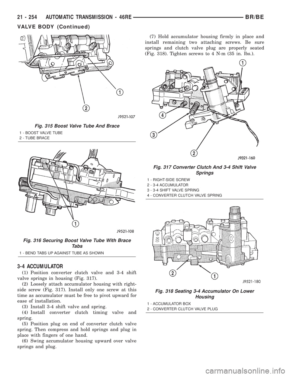
3-4 ACCUMULATOR
(1) Position converter clutch valve and 3-4 shift
valve springs in housing (Fig. 317).
(2) Loosely attach accumulator housing with right-
side screw (Fig. 317). Install only one screw at this
time as accumulator must be free to pivot upward for
ease of installation.
(3) Install 3-4 shift valve and spring.
(4) Install converter clutch timing valve and
spring.
(5) Position plug on end of converter clutch valve
spring. Then compress and hold springs and plug in
place with fingers of one hand.
(6) Swing accumulator housing upward over valve
springs and plug.(7) Hold accumulator housing firmly in place and
install remaining two attaching screws. Be sure
springs and clutch valve plug are properly seated
(Fig. 318). Tighten screws to 4 N´m (35 in. lbs.).
Fig. 315 Boost Valve Tube And Brace
1 - BOOST VALVE TUBE
2 - TUBE BRACE
Fig. 316 Securing Boost Valve Tube With Brace
Tabs
1 - BEND TABS UP AGAINST TUBE AS SHOWN
Fig. 317 Converter Clutch And 3-4 Shift Valve
Springs
1 - RIGHT-SIDE SCREW
2 - 3-4 ACCUMULATOR
3 - 3-4 SHIFT VALVE SPRING
4 - CONVERTER CLUTCH VALVE SPRING
Fig. 318 Seating 3-4 Accumulator On Lower
Housing
1 - ACCUMULATOR BOX
2 - CONVERTER CLUTCH VALVE PLUG
21 - 254 AUTOMATIC TRANSMISSION - 46REBR/BE
VALVE BODY (Continued)
Page 1708 of 2255
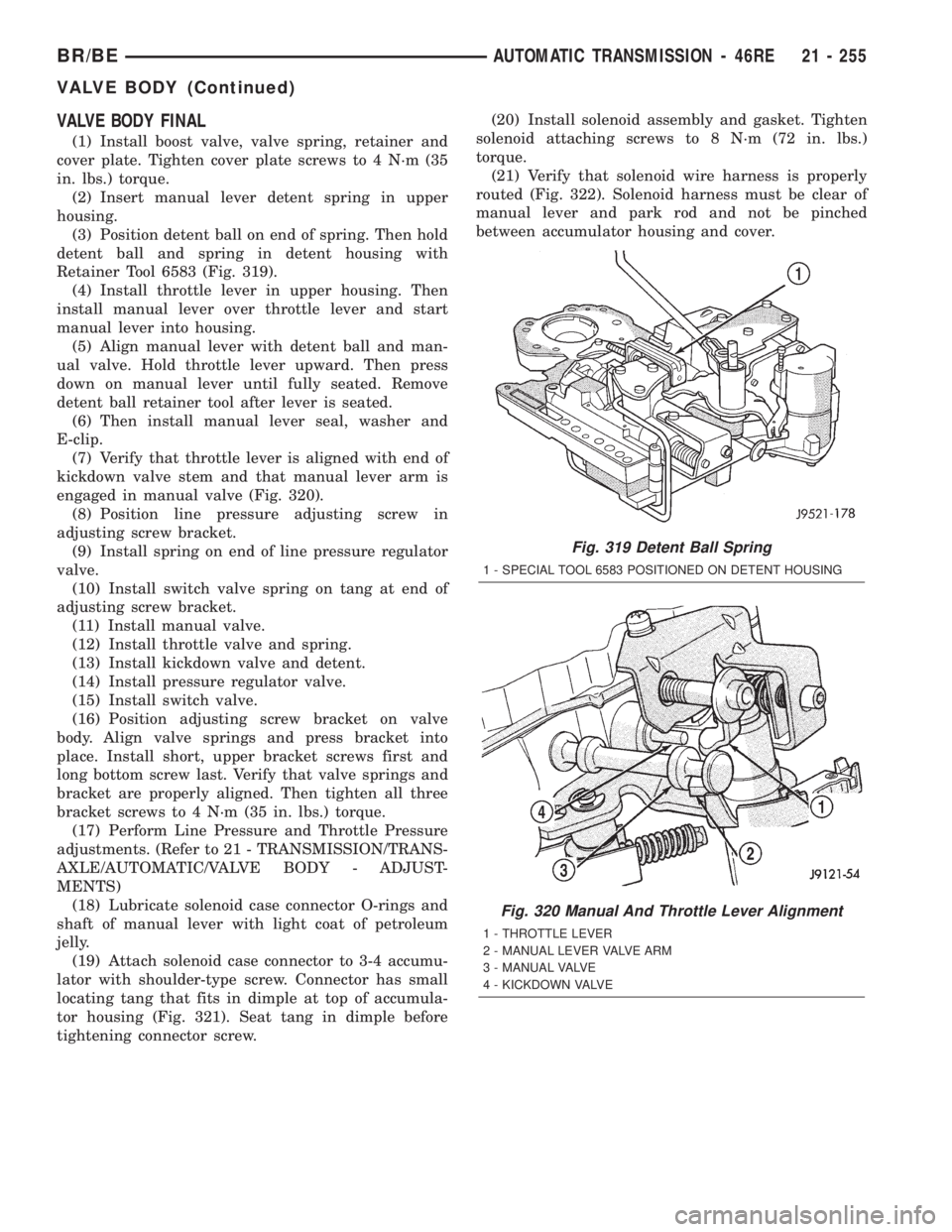
VALVE BODY FINAL
(1) Install boost valve, valve spring, retainer and
cover plate. Tighten cover plate screws to 4 N´m (35
in. lbs.) torque.
(2) Insert manual lever detent spring in upper
housing.
(3) Position detent ball on end of spring. Then hold
detent ball and spring in detent housing with
Retainer Tool 6583 (Fig. 319).
(4) Install throttle lever in upper housing. Then
install manual lever over throttle lever and start
manual lever into housing.
(5) Align manual lever with detent ball and man-
ual valve. Hold throttle lever upward. Then press
down on manual lever until fully seated. Remove
detent ball retainer tool after lever is seated.
(6) Then install manual lever seal, washer and
E-clip.
(7) Verify that throttle lever is aligned with end of
kickdown valve stem and that manual lever arm is
engaged in manual valve (Fig. 320).
(8) Position line pressure adjusting screw in
adjusting screw bracket.
(9) Install spring on end of line pressure regulator
valve.
(10) Install switch valve spring on tang at end of
adjusting screw bracket.
(11) Install manual valve.
(12) Install throttle valve and spring.
(13) Install kickdown valve and detent.
(14) Install pressure regulator valve.
(15) Install switch valve.
(16) Position adjusting screw bracket on valve
body. Align valve springs and press bracket into
place. Install short, upper bracket screws first and
long bottom screw last. Verify that valve springs and
bracket are properly aligned. Then tighten all three
bracket screws to 4 N´m (35 in. lbs.) torque.
(17) Perform Line Pressure and Throttle Pressure
adjustments. (Refer to 21 - TRANSMISSION/TRANS-
AXLE/AUTOMATIC/VALVE BODY - ADJUST-
MENTS)
(18) Lubricate solenoid case connector O-rings and
shaft of manual lever with light coat of petroleum
jelly.
(19) Attach solenoid case connector to 3-4 accumu-
lator with shoulder-type screw. Connector has small
locating tang that fits in dimple at top of accumula-
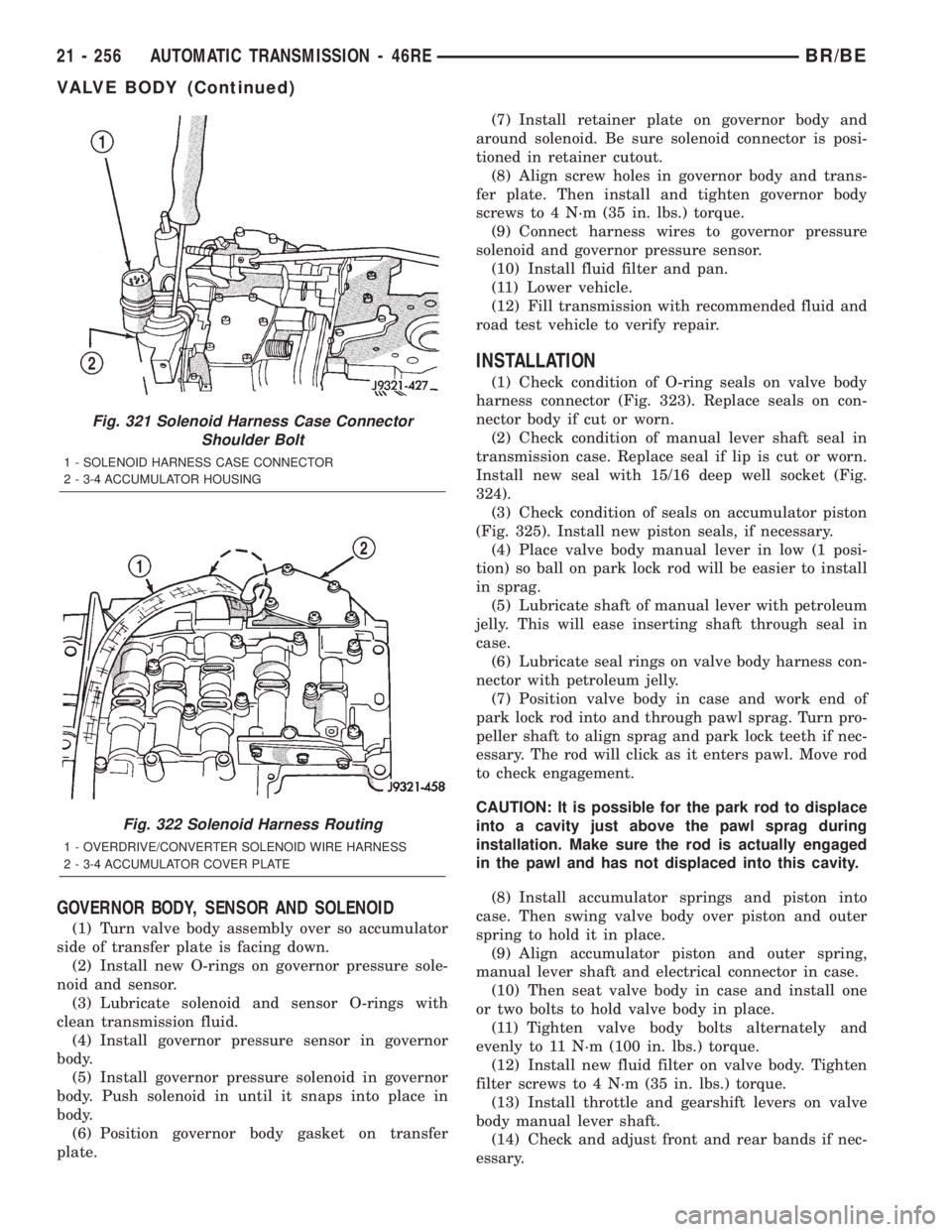
tor housing (Fig. 321). Seat tang in dimple before
tightening connector screw.(20) Install solenoid assembly and gasket. Tighten
solenoid attaching screws to 8 N´m (72 in. lbs.)
torque.
(21) Verify that solenoid wire harness is properly
routed (Fig. 322). Solenoid harness must be clear of
manual lever and park rod and not be pinched
between accumulator housing and cover.
Fig. 319 Detent Ball Spring
1 - SPECIAL TOOL 6583 POSITIONED ON DETENT HOUSING
Fig. 320 Manual And Throttle Lever Alignment
1 - THROTTLE LEVER
2 - MANUAL LEVER VALVE ARM
3 - MANUAL VALVE
4 - KICKDOWN VALVE
BR/BEAUTOMATIC TRANSMISSION - 46RE 21 - 255
VALVE BODY (Continued)
Page 1709 of 2255
GOVERNOR BODY, SENSOR AND SOLENOID
(1) Turn valve body assembly over so accumulator
side of transfer plate is facing down.
(2) Install new O-rings on governor pressure sole-
noid and sensor.
(3) Lubricate solenoid and sensor O-rings with
clean transmission fluid.
(4) Install governor pressure sensor in governor
body.
(5) Install governor pressure solenoid in governor
body. Push solenoid in until it snaps into place in
body.
(6) Position governor body gasket on transfer
plate.(7) Install retainer plate on governor body and
around solenoid. Be sure solenoid connector is posi-
tioned in retainer cutout.
(8) Align screw holes in governor body and trans-
fer plate. Then install and tighten governor body
screws to 4 N´m (35 in. lbs.) torque.
(9) Connect harness wires to governor pressure
solenoid and governor pressure sensor.
(10) Install fluid filter and pan.
(11) Lower vehicle.
(12) Fill transmission with recommended fluid and
road test vehicle to verify repair.
INSTALLATION
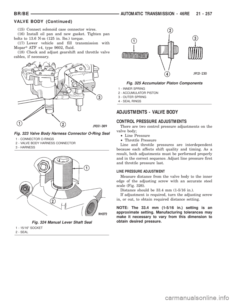
(1) Check condition of O-ring seals on valve body
harness connector (Fig. 323). Replace seals on con-
nector body if cut or worn.
(2) Check condition of manual lever shaft seal in
transmission case. Replace seal if lip is cut or worn.
Install new seal with 15/16 deep well socket (Fig.
324).
(3) Check condition of seals on accumulator piston
(Fig. 325). Install new piston seals, if necessary.
(4) Place valve body manual lever in low (1 posi-
tion) so ball on park lock rod will be easier to install
in sprag.
(5) Lubricate shaft of manual lever with petroleum
jelly. This will ease inserting shaft through seal in
case.
(6) Lubricate seal rings on valve body harness con-
nector with petroleum jelly.
(7) Position valve body in case and work end of
park lock rod into and through pawl sprag. Turn pro-
peller shaft to align sprag and park lock teeth if nec-
essary. The rod will click as it enters pawl. Move rod
to check engagement.
CAUTION: It is possible for the park rod to displace
into a cavity just above the pawl sprag during
installation. Make sure the rod is actually engaged
in the pawl and has not displaced into this cavity.
(8) Install accumulator springs and piston into
case. Then swing valve body over piston and outer
spring to hold it in place.
(9) Align accumulator piston and outer spring,
manual lever shaft and electrical connector in case.
(10) Then seat valve body in case and install one
or two bolts to hold valve body in place.
(11) Tighten valve body bolts alternately and
evenly to 11 N´m (100 in. lbs.) torque.
(12) Install new fluid filter on valve body. Tighten
filter screws to 4 N´m (35 in. lbs.) torque.
(13) Install throttle and gearshift levers on valve
body manual lever shaft.
(14) Check and adjust front and rear bands if nec-
essary.
Fig. 321 Solenoid Harness Case Connector
Shoulder Bolt
1 - SOLENOID HARNESS CASE CONNECTOR
2 - 3-4 ACCUMULATOR HOUSING
Fig. 322 Solenoid Harness Routing
1 - OVERDRIVE/CONVERTER SOLENOID WIRE HARNESS
2 - 3-4 ACCUMULATOR COVER PLATE
21 - 256 AUTOMATIC TRANSMISSION - 46REBR/BE
VALVE BODY (Continued)
Page 1710 of 2255
(15) Connect solenoid case connector wires.
(16) Install oil pan and new gasket. Tighten pan
bolts to 13.6 N´m (125 in. lbs.) torque.
(17) Lower vehicle and fill transmission with
MopartATF +4, type 9602, fluid.
(18) Check and adjust gearshift and throttle valve
cables, if necessary.
ADJUSTMENTS - VALVE BODY
CONTROL PRESSURE ADJUSTMENTS
There are two control pressure adjustments on the
valve body;
²Line Pressure
²Throttle Pressure
Line and throttle pressures are interdependent
because each affects shift quality and timing. As a
result, both adjustments must be performed properly
and in the correct sequence. Adjust line pressure first
and throttle pressure last.
LINE PRESSURE ADJUSTMENT
Measure distance from the valve body to the inner
edge of the adjusting screw with an accurate steel
scale (Fig. 326).
Distance should be 33.4 mm (1-5/16 in.).
If adjustment is required, turn the adjusting screw
in, or out, to obtain required distance setting.
NOTE: The 33.4 mm (1-5/16 in.) setting is an
approximate setting. Manufacturing tolerances may
make it necessary to vary from this dimension to
obtain desired pressure.
Fig. 323 Valve Body Harness Connector O-Ring Seal
1 - CONNECTOR O-RINGS
2 - VALVE BODY HARNESS CONNECTOR
3 - HARNESS
Fig. 324 Manual Lever Shaft Seal
1 - 15/16©© SOCKET
2 - SEAL
Fig. 325 Accumulator Piston Components
1 - INNER SPRING
2 - ACCUMULATOR PISTON
3 - OUTER SPRING
4 - SEAL RINGS
BR/BEAUTOMATIC TRANSMISSION - 46RE 21 - 257
VALVE BODY (Continued)