DODGE RAM 2002 Service Repair Manual
Manufacturer: DODGE, Model Year: 2002, Model line: RAM, Model: DODGE RAM 2002Pages: 2255, PDF Size: 62.07 MB
Page 1711 of 2255
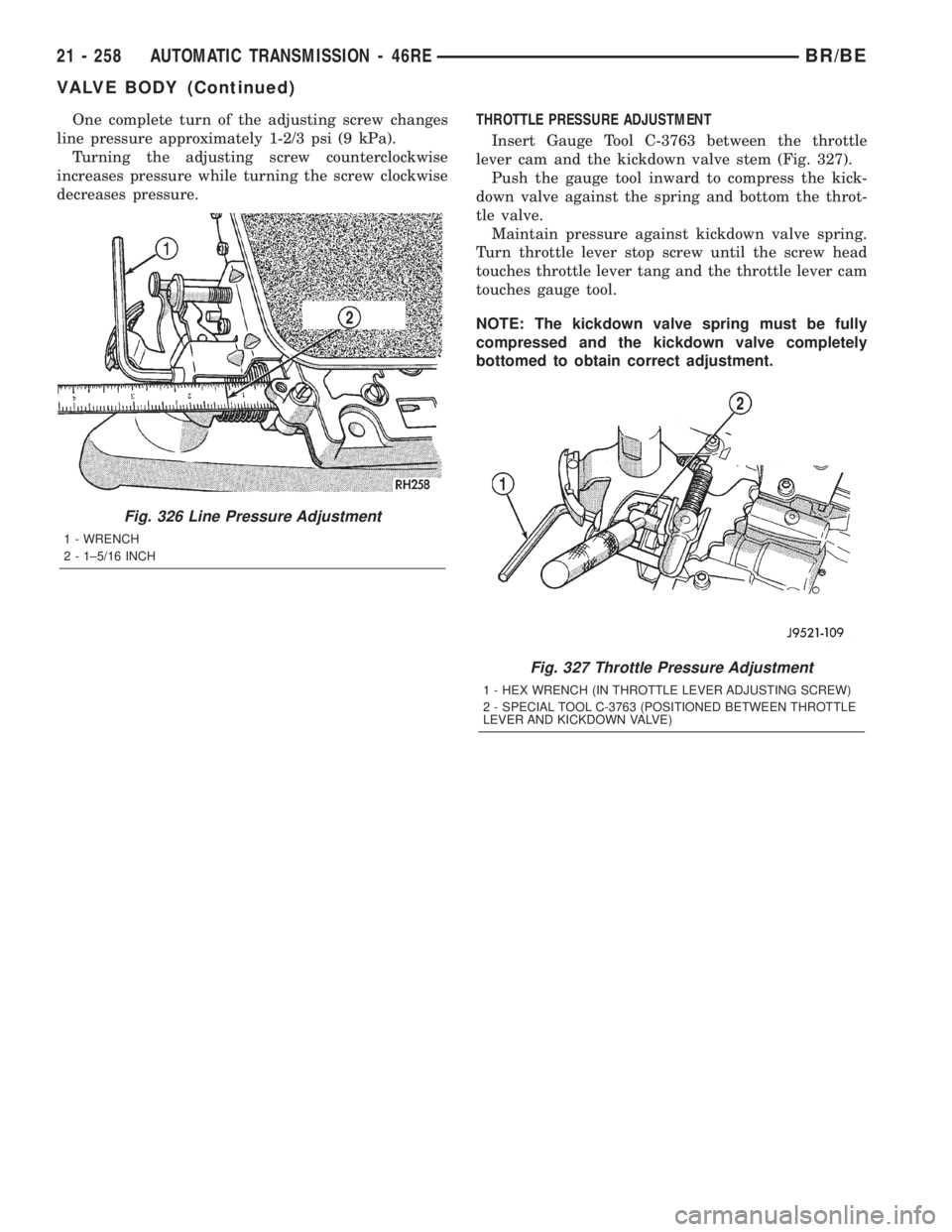
One complete turn of the adjusting screw changes
line pressure approximately 1-2/3 psi (9 kPa).
Turning the adjusting screw counterclockwise
increases pressure while turning the screw clockwise
decreases pressure.THROTTLE PRESSURE ADJUSTMENT
Insert Gauge Tool C-3763 between the throttle
lever cam and the kickdown valve stem (Fig. 327).
Push the gauge tool inward to compress the kick-
down valve against the spring and bottom the throt-
tle valve.
Maintain pressure against kickdown valve spring.
Turn throttle lever stop screw until the screw head
touches throttle lever tang and the throttle lever cam
touches gauge tool.
NOTE: The kickdown valve spring must be fully
compressed and the kickdown valve completely
bottomed to obtain correct adjustment.
Fig. 326 Line Pressure Adjustment
1 - WRENCH
2 - 1±5/16 INCH
Fig. 327 Throttle Pressure Adjustment
1 - HEX WRENCH (IN THROTTLE LEVER ADJUSTING SCREW)
2 - SPECIAL TOOL C-3763 (POSITIONED BETWEEN THROTTLE
LEVER AND KICKDOWN VALVE)
21 - 258 AUTOMATIC TRANSMISSION - 46REBR/BE
VALVE BODY (Continued)
Page 1712 of 2255
AUTOMATIC TRANSMISSION - 47RE
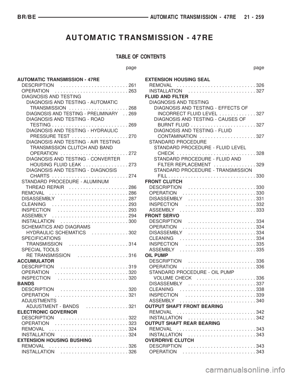
TABLE OF CONTENTS
page page
AUTOMATIC TRANSMISSION - 47RE
DESCRIPTION........................261
OPERATION..........................263
DIAGNOSIS AND TESTING
DIAGNOSIS AND TESTING - AUTOMATIC
TRANSMISSION.....................268
DIAGNOSIS AND TESTING - PRELIMINARY. . 269
DIAGNOSIS AND TESTING - ROAD
TESTING...........................269
DIAGNOSIS AND TESTING - HYDRAULIC
PRESSURE TEST....................270
DIAGNOSIS AND TESTING - AIR TESTING
TRANSMISSION CLUTCH AND BAND
OPERATION........................272
DIAGNOSIS AND TESTING - CONVERTER
HOUSING FLUID LEAK................273
DIAGNOSIS AND TESTING - DIAGNOSIS
CHARTS...........................274
STANDARD PROCEDURE - ALUMINUM
THREAD REPAIR.....................286
REMOVAL............................286
DISASSEMBLY........................287
CLEANING...........................293
INSPECTION.........................293
ASSEMBLY...........................294
INSTALLATION........................300
SCHEMATICS AND DIAGRAMS
HYDRAULIC SCHEMATICS.............302
SPECIFICATIONS
TRANSMISSION.....................314
SPECIAL TOOLS
RE TRANSMISSION..................316
ACCUMULATOR
DESCRIPTION........................319
OPERATION..........................320
INSPECTION.........................320
BANDS
DESCRIPTION........................320
OPERATION..........................321
ADJUSTMENTS
ADJUSTMENT - BANDS...............321
ELECTRONIC GOVERNOR
DESCRIPTION........................322
OPERATION..........................323
REMOVAL............................324
INSTALLATION........................324
EXTENSION HOUSING BUSHING
REMOVAL............................326
INSTALLATION........................326EXTENSION HOUSING SEAL
REMOVAL............................326
INSTALLATION........................327
FLUID AND FILTER
DIAGNOSIS AND TESTING
DIAGNOSIS AND TESTING - EFFECTS OF
INCORRECT FLUID LEVEL.............327
DIAGNOSIS AND TESTING - CAUSES OF
BURNT FLUID.......................327
DIAGNOSIS AND TESTING - FLUID
CONTAMINATION....................327
STANDARD PROCEDURE
STANDARD PROCEDURE - FLUID LEVEL
CHECK............................328
STANDARD PROCEDURE - FLUID AND
FILTER REPLACEMENT...............329
STANDARD PROCEDURE - TRANSMISSION
FILL...............................330
FRONT CLUTCH
DESCRIPTION........................330
OPERATION..........................330
DISASSEMBLY........................331
INSPECTION.........................332
ASSEMBLY...........................333
FRONT SERVO
DESCRIPTION........................334
OPERATION..........................334
DISASSEMBLY........................334
CLEANING...........................334
INSPECTION.........................335
ASSEMBLY...........................335
OIL PUMP
DESCRIPTION........................336
OPERATION..........................336
STANDARD PROCEDURE - OIL PUMP
VOLUME CHECK.....................336
DISASSEMBLY........................337
CLEANING...........................338
INSPECTION.........................339
ASSEMBLY...........................340
OUTPUT SHAFT FRONT BEARING
REMOVAL............................342
INSTALLATION........................342
OUTPUT SHAFT REAR BEARING
REMOVAL............................343
INSTALLATION........................343
OVERDRIVE CLUTCH
DESCRIPTION........................343
OPERATION..........................343
BR/BEAUTOMATIC TRANSMISSION - 47RE 21 - 259
Page 1713 of 2255
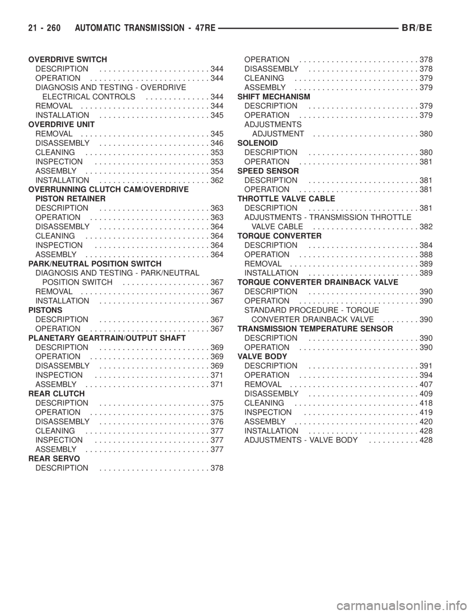
OVERDRIVE SWITCH
DESCRIPTION........................344
OPERATION..........................344
DIAGNOSIS AND TESTING - OVERDRIVE
ELECTRICAL CONTROLS..............344
REMOVAL............................344
INSTALLATION........................345
OVERDRIVE UNIT
REMOVAL............................345
DISASSEMBLY........................346
CLEANING...........................353
INSPECTION.........................353
ASSEMBLY...........................354
INSTALLATION........................362
OVERRUNNING CLUTCH CAM/OVERDRIVE
PISTON RETAINER
DESCRIPTION........................363
OPERATION..........................363
DISASSEMBLY........................364
CLEANING...........................364
INSPECTION.........................364
ASSEMBLY...........................364
PARK/NEUTRAL POSITION SWITCH
DIAGNOSIS AND TESTING - PARK/NEUTRAL
POSITION SWITCH...................367
REMOVAL............................367
INSTALLATION........................367
PISTONS
DESCRIPTION........................367
OPERATION..........................367
PLANETARY GEARTRAIN/OUTPUT SHAFT
DESCRIPTION........................369
OPERATION..........................369
DISASSEMBLY........................369
INSPECTION.........................371
ASSEMBLY...........................371
REAR CLUTCH
DESCRIPTION........................375
OPERATION..........................375
DISASSEMBLY........................376
CLEANING...........................377
INSPECTION.........................377
ASSEMBLY...........................377
REAR SERVO
DESCRIPTION........................378OPERATION..........................378
DISASSEMBLY........................378
CLEANING...........................379
ASSEMBLY...........................379
SHIFT MECHANISM
DESCRIPTION........................379
OPERATION..........................379
ADJUSTMENTS
ADJUSTMENT.......................380
SOLENOID
DESCRIPTION........................380
OPERATION..........................381
SPEED SENSOR
DESCRIPTION........................381
OPERATION..........................381
THROTTLE VALVE CABLE
DESCRIPTION........................381
ADJUSTMENTS - TRANSMISSION THROTTLE
VALVE CABLE.......................382
TORQUE CONVERTER
DESCRIPTION........................384
OPERATION..........................388
REMOVAL............................389
INSTALLATION........................389
TORQUE CONVERTER DRAINBACK VALVE
DESCRIPTION........................390
OPERATION..........................390
STANDARD PROCEDURE - TORQUE
CONVERTER DRAINBACK VALVE........390
TRANSMISSION TEMPERATURE SENSOR
DESCRIPTION........................390
OPERATION..........................390
VALVE BODY
DESCRIPTION........................391
OPERATION..........................394
REMOVAL............................407
DISASSEMBLY........................409
CLEANING...........................418
INSPECTION.........................419
ASSEMBLY...........................420
INSTALLATION........................428
ADJUSTMENTS - VALVE BODY...........428
21 - 260 AUTOMATIC TRANSMISSION - 47REBR/BE
Page 1714 of 2255
AUTOMATIC TRANSMISSION -
47RE
DESCRIPTION
The 47RE (Fig. 1) is a four speed fully automatic
transmissions with an electronic governor. The 47RE
is equipped with a lock-up clutch in the torque con-
verter. First through third gear ranges are provided
by the clutches, bands, overrunning clutch, and plan-
etary gear sets in the transmission. Fourth gear
range is provided by the overdrive unit that contains
an overdrive clutch, direct clutch, planetary gear set,
and overrunning clutch.The transmission contains a front, rear, and direct
clutch which function as the input driving compo-
nents. It also contains the kickdown (front) and the
low/reverse (rear) bands which, along with the over-
running clutch and overdrive clutch, serve as the
holding components. The driving and holding compo-
nents combine to select the necessary planetary gear
components, in the front, rear, or overdrive planetary
gear set, transfer the engine power from the input
shaft through to the output shaft.
The valve body is mounted to the lower side of the
transmission and contains the valves to control pres-
sure regulation, fluid flow control, and clutch/band
application. The oil pump is mounted at the front of
the transmission and is driven by the torque con-
verter hub. The pump supplies the oil pressure nec-
essary for clutch/band actuation and transmission
lubrication.
BR/BEAUTOMATIC TRANSMISSION - 47RE 21 - 261
Page 1715 of 2255
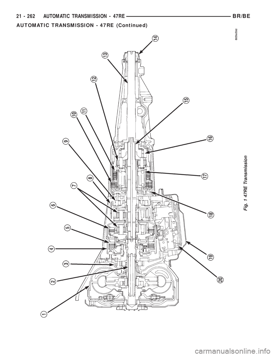
Fig. 1 47RE Transmission
21 - 262 AUTOMATIC TRANSMISSION - 47REBR/BE
AUTOMATIC TRANSMISSION - 47RE (Continued)
Page 1716 of 2255
IDENTIFICATION
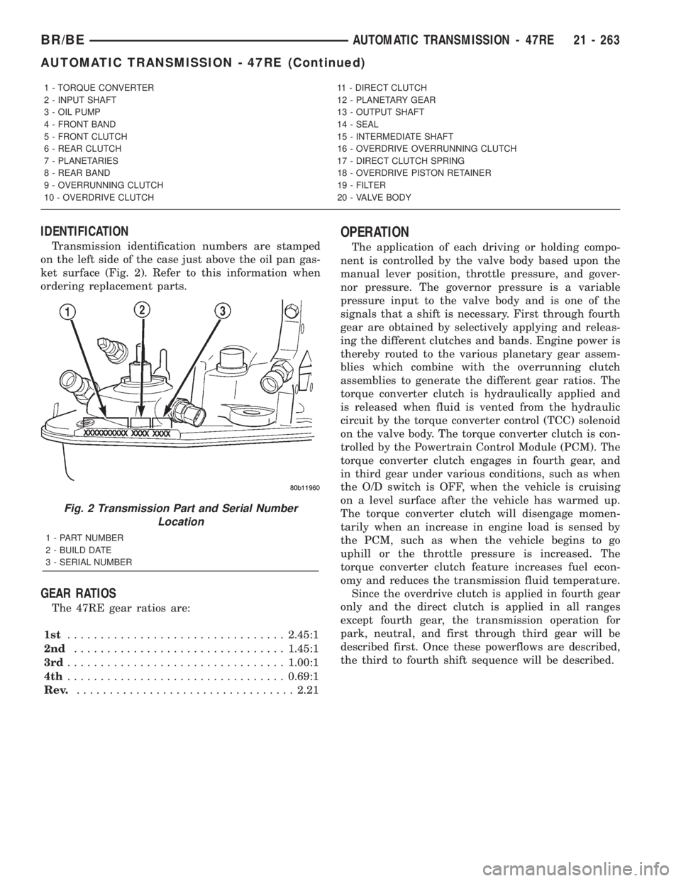
Transmission identification numbers are stamped
on the left side of the case just above the oil pan gas-
ket surface (Fig. 2). Refer to this information when
ordering replacement parts.
GEAR RATIOS
The 47RE gear ratios are:
1st.................................2.45:1
2nd................................1.45:1
3rd.................................1.00:1
4th.................................0.69:1
Rev..................................2.21
OPERATION
The application of each driving or holding compo-
nent is controlled by the valve body based upon the
manual lever position, throttle pressure, and gover-
nor pressure. The governor pressure is a variable
pressure input to the valve body and is one of the
signals that a shift is necessary. First through fourth
gear are obtained by selectively applying and releas-
ing the different clutches and bands. Engine power is
thereby routed to the various planetary gear assem-
blies which combine with the overrunning clutch
assemblies to generate the different gear ratios. The
torque converter clutch is hydraulically applied and
is released when fluid is vented from the hydraulic
circuit by the torque converter control (TCC) solenoid
on the valve body. The torque converter clutch is con-
trolled by the Powertrain Control Module (PCM). The
torque converter clutch engages in fourth gear, and
in third gear under various conditions, such as when
the O/D switch is OFF, when the vehicle is cruising
on a level surface after the vehicle has warmed up.
The torque converter clutch will disengage momen-
tarily when an increase in engine load is sensed by
the PCM, such as when the vehicle begins to go
uphill or the throttle pressure is increased. The
torque converter clutch feature increases fuel econ-
omy and reduces the transmission fluid temperature.
Since the overdrive clutch is applied in fourth gear
only and the direct clutch is applied in all ranges
except fourth gear, the transmission operation for
park, neutral, and first through third gear will be
described first. Once these powerflows are described,
the third to fourth shift sequence will be described.
1 - TORQUE CONVERTER 11 - DIRECT CLUTCH
2 - INPUT SHAFT 12 - PLANETARY GEAR
3 - OIL PUMP 13 - OUTPUT SHAFT
4 - FRONT BAND 14 - SEAL
5 - FRONT CLUTCH 15 - INTERMEDIATE SHAFT
6 - REAR CLUTCH 16 - OVERDRIVE OVERRUNNING CLUTCH
7 - PLANETARIES 17 - DIRECT CLUTCH SPRING
8 - REAR BAND 18 - OVERDRIVE PISTON RETAINER
9 - OVERRUNNING CLUTCH 19 - FILTER
10 - OVERDRIVE CLUTCH 20 - VALVE BODY
Fig. 2 Transmission Part and Serial Number
Location
1 - PART NUMBER
2 - BUILD DATE
3 - SERIAL NUMBER
BR/BEAUTOMATIC TRANSMISSION - 47RE 21 - 263
AUTOMATIC TRANSMISSION - 47RE (Continued)
Page 1717 of 2255
PARK POWERFLOW
As the engine is running and the crankshaft is
rotating, the flexplate and torque converter, which
are also bolted to it, are all rotating in a clockwise
direction as viewed from the front of the engine. The
notched hub of the torque converter is connected to
the oil pump's internal gear, supplying the transmis-
sion with oil pressure. As the converter turns, it
turns the input shaft in a clockwise direction. As the
input shaft is rotating, the front clutch hub-rear
clutch retainer and all their associated parts are also
rotating, all being directly connected to the input
shaft. The power flow from the engine through the
front clutch hub and rear clutch retainer stops at the
rear clutch retainer. Therefore, no power flow to the
output shaft occurs because no clutches are applied.
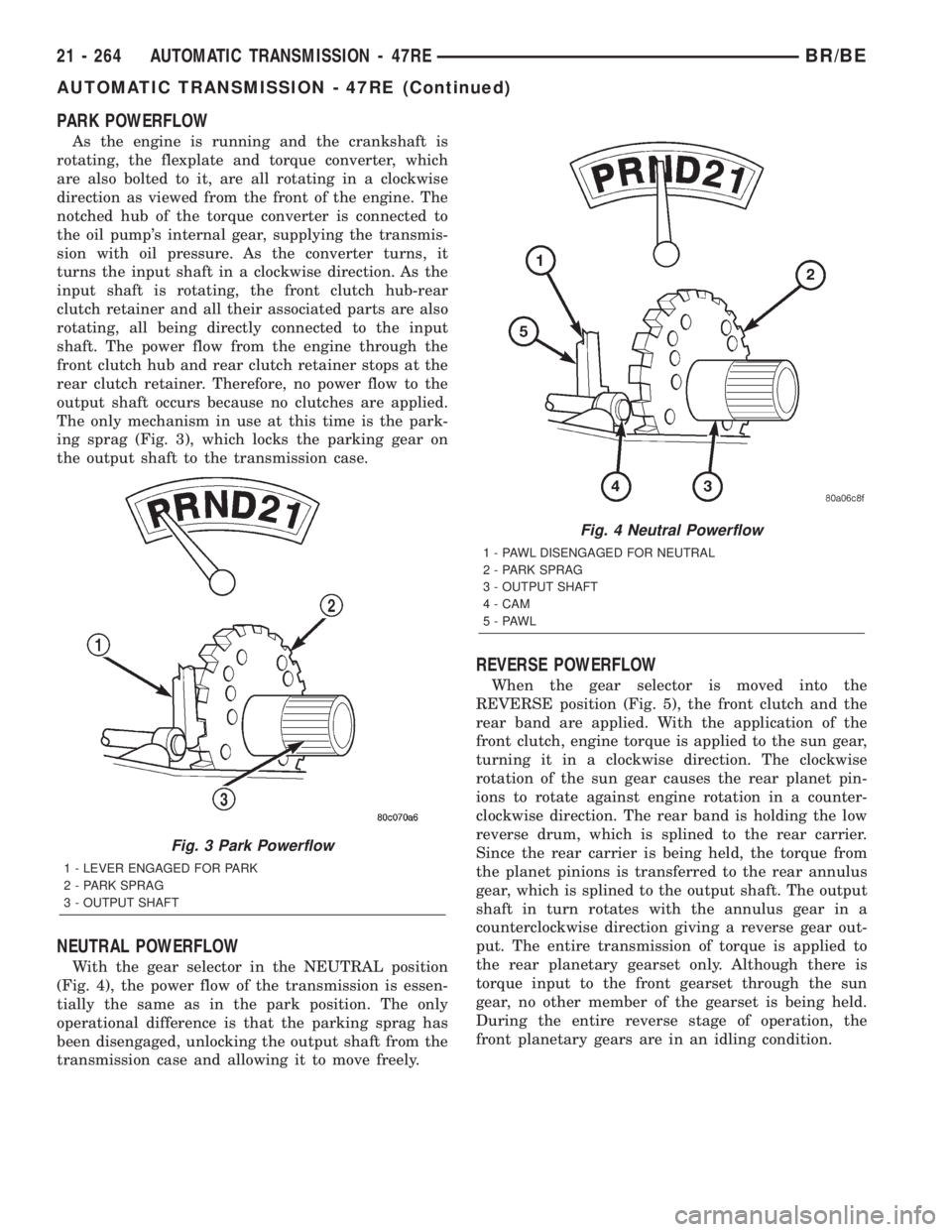
The only mechanism in use at this time is the park-
ing sprag (Fig. 3), which locks the parking gear on
the output shaft to the transmission case.
NEUTRAL POWERFLOW
With the gear selector in the NEUTRAL position
(Fig. 4), the power flow of the transmission is essen-
tially the same as in the park position. The only
operational difference is that the parking sprag has
been disengaged, unlocking the output shaft from the
transmission case and allowing it to move freely.
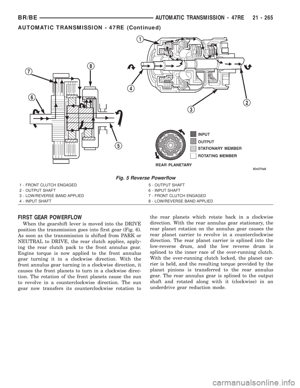
REVERSE POWERFLOW
When the gear selector is moved into the
REVERSE position (Fig. 5), the front clutch and the
rear band are applied. With the application of the
front clutch, engine torque is applied to the sun gear,
turning it in a clockwise direction. The clockwise
rotation of the sun gear causes the rear planet pin-
ions to rotate against engine rotation in a counter-
clockwise direction. The rear band is holding the low
reverse drum, which is splined to the rear carrier.
Since the rear carrier is being held, the torque from
the planet pinions is transferred to the rear annulus
gear, which is splined to the output shaft. The output
shaft in turn rotates with the annulus gear in a
counterclockwise direction giving a reverse gear out-
put. The entire transmission of torque is applied to
the rear planetary gearset only. Although there is
torque input to the front gearset through the sun
gear, no other member of the gearset is being held.
During the entire reverse stage of operation, the
front planetary gears are in an idling condition.
Fig. 3 Park Powerflow
1 - LEVER ENGAGED FOR PARK
2 - PARK SPRAG
3 - OUTPUT SHAFT
Fig. 4 Neutral Powerflow
1 - PAWL DISENGAGED FOR NEUTRAL
2 - PARK SPRAG
3 - OUTPUT SHAFT
4 - CAM
5-PAWL
21 - 264 AUTOMATIC TRANSMISSION - 47REBR/BE
AUTOMATIC TRANSMISSION - 47RE (Continued)
Page 1718 of 2255
FIRST GEAR POWERFLOW
When the gearshift lever is moved into the DRIVE
position the transmission goes into first gear (Fig. 6).
As soon as the transmission is shifted from PARK or
NEUTRAL to DRIVE, the rear clutch applies, apply-
ing the rear clutch pack to the front annulus gear.
Engine torque is now applied to the front annulus
gear turning it in a clockwise direction. With the
front annulus gear turning in a clockwise direction, it
causes the front planets to turn in a clockwise direc-
tion. The rotation of the front planets cause the sun
to revolve in a counterclockwise direction. The sun
gear now transfers its counterclockwise rotation tothe rear planets which rotate back in a clockwise
direction. With the rear annulus gear stationary, the
rear planet rotation on the annulus gear causes the
rear planet carrier to revolve in a counterclockwise
direction. The rear planet carrier is splined into the
low-reverse drum, and the low reverse drum is
splined to the inner race of the over-running clutch.
With the over-running clutch locked, the planet car-
rier is held, and the resulting torque provided by the
planet pinions is transferred to the rear annulus
gear. The rear annulus gear is splined to the output
shaft and rotated along with it (clockwise) in an
underdrive gear reduction mode.
Fig. 5 Reverse Powerflow
1 - FRONT CLUTCH ENGAGED 5 - OUTPUT SHAFT
2 - OUTPUT SHAFT 6 - INPUT SHAFT
3 - LOW/REVERSE BAND APPLIED 7 - FRONT CLUTCH ENGAGED
4 - INPUT SHAFT 8 - LOW/REVERSE BAND APPLIED
BR/BEAUTOMATIC TRANSMISSION - 47RE 21 - 265
AUTOMATIC TRANSMISSION - 47RE (Continued)
Page 1719 of 2255
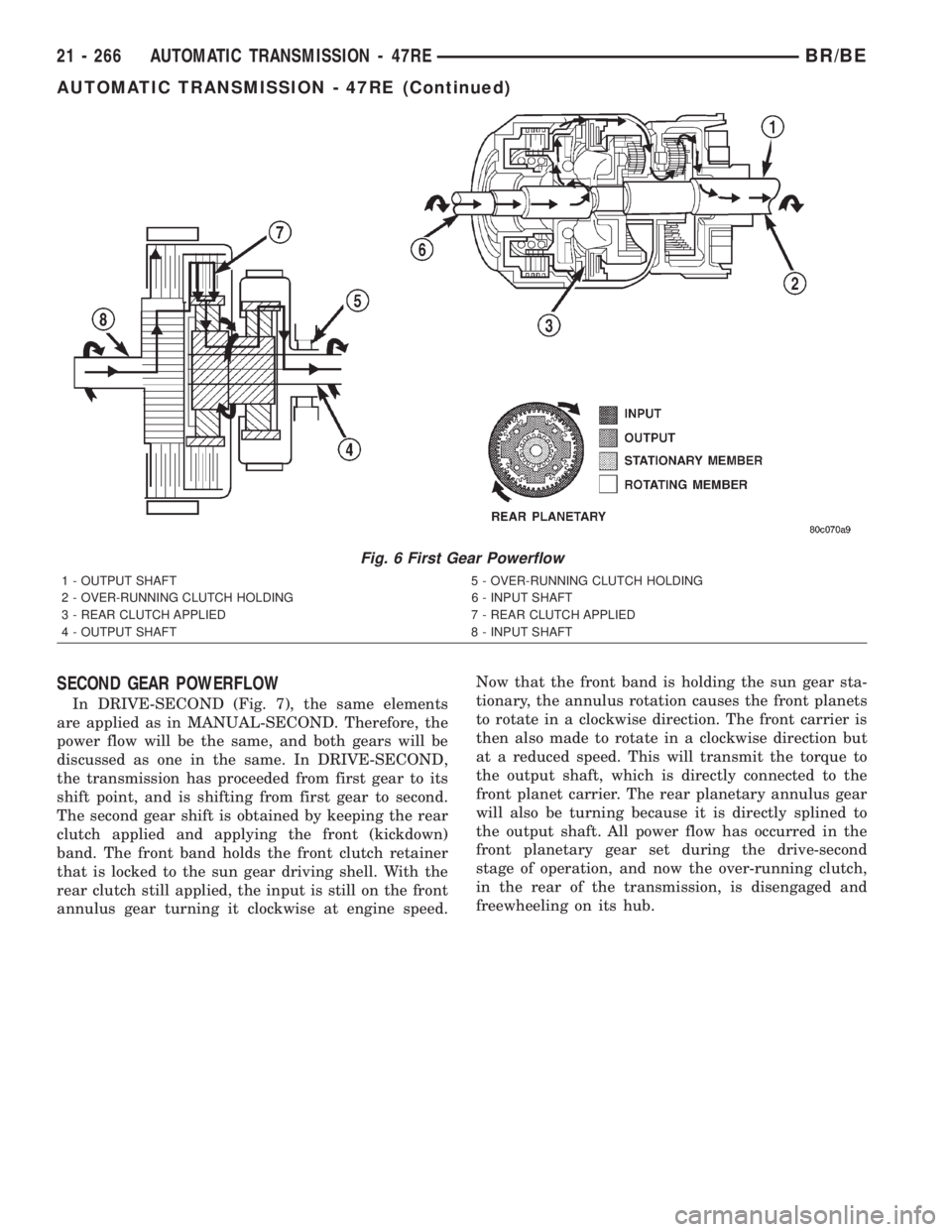
SECOND GEAR POWERFLOW
In DRIVE-SECOND (Fig. 7), the same elements
are applied as in MANUAL-SECOND. Therefore, the
power flow will be the same, and both gears will be
discussed as one in the same. In DRIVE-SECOND,
the transmission has proceeded from first gear to its
shift point, and is shifting from first gear to second.
The second gear shift is obtained by keeping the rear
clutch applied and applying the front (kickdown)
band. The front band holds the front clutch retainer
that is locked to the sun gear driving shell. With the
rear clutch still applied, the input is still on the front
annulus gear turning it clockwise at engine speed.Now that the front band is holding the sun gear sta-
tionary, the annulus rotation causes the front planets
to rotate in a clockwise direction. The front carrier is
then also made to rotate in a clockwise direction but
at a reduced speed. This will transmit the torque to
the output shaft, which is directly connected to the
front planet carrier. The rear planetary annulus gear
will also be turning because it is directly splined to
the output shaft. All power flow has occurred in the
front planetary gear set during the drive-second
stage of operation, and now the over-running clutch,
in the rear of the transmission, is disengaged and
freewheeling on its hub.
Fig. 6 First Gear Powerflow
1 - OUTPUT SHAFT 5 - OVER-RUNNING CLUTCH HOLDING
2 - OVER-RUNNING CLUTCH HOLDING 6 - INPUT SHAFT
3 - REAR CLUTCH APPLIED 7 - REAR CLUTCH APPLIED
4 - OUTPUT SHAFT 8 - INPUT SHAFT
21 - 266 AUTOMATIC TRANSMISSION - 47REBR/BE
AUTOMATIC TRANSMISSION - 47RE (Continued)
Page 1720 of 2255
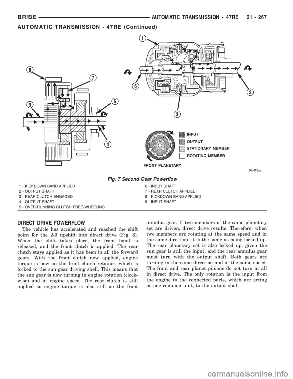
DIRECT DRIVE POWERFLOW
The vehicle has accelerated and reached the shift
point for the 2-3 upshift into direct drive (Fig. 8).
When the shift takes place, the front band is
released, and the front clutch is applied. The rear
clutch stays applied as it has been in all the forward
gears. With the front clutch now applied, engine
torque is now on the front clutch retainer, which is
locked to the sun gear driving shell. This means that
the sun gear is now turning in engine rotation (clock-
wise) and at engine speed. The rear clutch is still
applied so engine torque is also still on the frontannulus gear. If two members of the same planetary
set are driven, direct drive results. Therefore, when
two members are rotating at the same speed and in
the same direction, it is the same as being locked up.
The rear planetary set is also locked up, given the
sun gear is still the input, and the rear annulus gear
must turn with the output shaft. Both gears are
turning in the same direction and at the same speed.
The front and rear planet pinions do not turn at all
in direct drive. The only rotation is the input from
the engine to the connected parts, which are acting
as one common unit, to the output shaft.
Fig. 7 Second Gear Powerflow
1 - KICKDOWN BAND APPLIED 6 - INPUT SHAFT
2 - OUTPUT SHAFT 7 - REAR CLUTCH APPLIED
3 - REAR CLUTCH ENGAGED 8 - KICKDOWN BAND APPLIED
4 - OUTPUT SHAFT 9 - INPUT SHAFT
5 - OVER-RUNNING CLUTCH FREE-WHEELING
BR/BEAUTOMATIC TRANSMISSION - 47RE 21 - 267
AUTOMATIC TRANSMISSION - 47RE (Continued)