compression ratio DODGE RAM 2002 Service User Guide
[x] Cancel search | Manufacturer: DODGE, Model Year: 2002, Model line: RAM, Model: DODGE RAM 2002Pages: 2255, PDF Size: 62.07 MB
Page 1115 of 2255
lower rails. Insert oil rail spacer first, then side
rails.
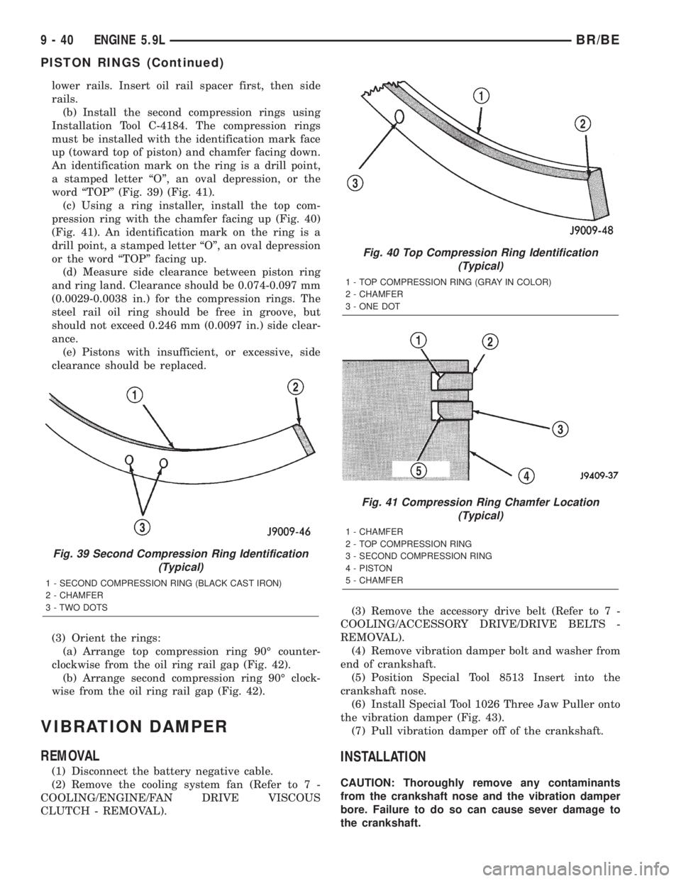
(b) Install the second compression rings using
Installation Tool C-4184. The compression rings
must be installed with the identification mark face
up (toward top of piston) and chamfer facing down.
An identification mark on the ring is a drill point,
a stamped letter ªOº, an oval depression, or the
word ªTOPº (Fig. 39) (Fig. 41).
(c) Using a ring installer, install the top com-
pression ring with the chamfer facing up (Fig. 40)
(Fig. 41). An identification mark on the ring is a
drill point, a stamped letter ªOº, an oval depression
or the word ªTOPº facing up.
(d) Measure side clearance between piston ring
and ring land. Clearance should be 0.074-0.097 mm
(0.0029-0.0038 in.) for the compression rings. The
steel rail oil ring should be free in groove, but
should not exceed 0.246 mm (0.0097 in.) side clear-
ance.
(e) Pistons with insufficient, or excessive, side
clearance should be replaced.
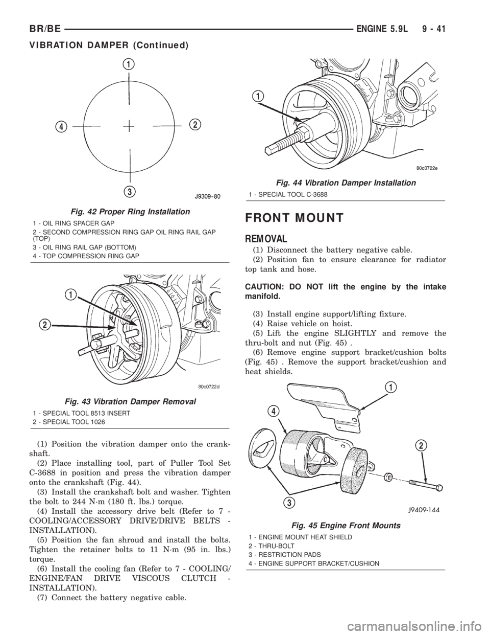
(3) Orient the rings:
(a) Arrange top compression ring 90É counter-
clockwise from the oil ring rail gap (Fig. 42).
(b) Arrange second compression ring 90É clock-
wise from the oil ring rail gap (Fig. 42).
VIBRATION DAMPER
REMOVAL
(1) Disconnect the battery negative cable.
(2) Remove the cooling system fan (Refer to 7 -
COOLING/ENGINE/FAN DRIVE VISCOUS
CLUTCH - REMOVAL).(3) Remove the accessory drive belt (Refer to 7 -
COOLING/ACCESSORY DRIVE/DRIVE BELTS -
REMOVAL).
(4) Remove vibration damper bolt and washer from
end of crankshaft.
(5) Position Special Tool 8513 Insert into the
crankshaft nose.
(6) Install Special Tool 1026 Three Jaw Puller onto
the vibration damper (Fig. 43).
(7) Pull vibration damper off of the crankshaft.
INSTALLATION
CAUTION: Thoroughly remove any contaminants
from the crankshaft nose and the vibration damper
bore. Failure to do so can cause sever damage to
the crankshaft.
Fig. 39 Second Compression Ring Identification
(Typical)
1 - SECOND COMPRESSION RING (BLACK CAST IRON)
2 - CHAMFER
3 - TWO DOTS
Fig. 40 Top Compression Ring Identification
(Typical)
1 - TOP COMPRESSION RING (GRAY IN COLOR)
2 - CHAMFER
3 - ONE DOT
Fig. 41 Compression Ring Chamfer Location
(Typical)
1 - CHAMFER
2 - TOP COMPRESSION RING
3 - SECOND COMPRESSION RING
4 - PISTON
5 - CHAMFER
9 - 40 ENGINE 5.9LBR/BE
PISTON RINGS (Continued)
Page 1116 of 2255
(1) Position the vibration damper onto the crank-
shaft.
(2) Place installing tool, part of Puller Tool Set
C-3688 in position and press the vibration damper
onto the crankshaft (Fig. 44).
(3) Install the crankshaft bolt and washer. Tighten
the bolt to 244 N´m (180 ft. lbs.) torque.
(4) Install the accessory drive belt (Refer to 7 -
COOLING/ACCESSORY DRIVE/DRIVE BELTS -
INSTALLATION).
(5) Position the fan shroud and install the bolts.
Tighten the retainer bolts to 11 N´m (95 in. lbs.)
torque.
(6) Install the cooling fan (Refer to 7 - COOLING/
ENGINE/FAN DRIVE VISCOUS CLUTCH -
INSTALLATION).
(7) Connect the battery negative cable.
FRONT MOUNT
REMOVAL
(1) Disconnect the battery negative cable.
(2) Position fan to ensure clearance for radiator
top tank and hose.
CAUTION: DO NOT lift the engine by the intake
manifold.
(3) Install engine support/lifting fixture.
(4) Raise vehicle on hoist.
(5) Lift the engine SLIGHTLY and remove the
thru-bolt and nut (Fig. 45) .
(6) Remove engine support bracket/cushion bolts
(Fig. 45) . Remove the support bracket/cushion and
heat shields.
Fig. 42 Proper Ring Installation
1 - OIL RING SPACER GAP
2 - SECOND COMPRESSION RING GAP OIL RING RAIL GAP
(TOP)
3 - OIL RING RAIL GAP (BOTTOM)
4 - TOP COMPRESSION RING GAP
Fig. 43 Vibration Damper Removal
1 - SPECIAL TOOL 8513 INSERT
2 - SPECIAL TOOL 1026
Fig. 44 Vibration Damper Installation
1 - SPECIAL TOOL C-3688
Fig. 45 Engine Front Mounts
1 - ENGINE MOUNT HEAT SHIELD
2 - THRU-BOLT
3 - RESTRICTION PADS
4 - ENGINE SUPPORT BRACKET/CUSHION
BR/BEENGINE 5.9L 9 - 41
VIBRATION DAMPER (Continued)
Page 1135 of 2255
CONDITION POSSIBLE CAUSES CORRECTION
7. Blown cylinder head gasket 7. Install new cylinder head gasket
8. Low compression 8. Test cylinder compression (Refer
to 9 - ENGINE - DIAGNOSIS AND
TESTING).
9. Burned, warped, or pitted valves 9. Install/Reface valves as
necessary
10. Plugged or restricted exhaust
system10. Install new parts as necessary
11. Faulty ignition cables 11. Replace any cracked or shorted
cables
12. Faulty ignition coil 12. Test and replace, as necessary
(Refer to 8 - ELECTRICAL/
IGNITION CONTROL/IGNITION
COIL - REMOVAL).
ENGINE STALLS OR ROUGH IDLE 1. Carbon build-up on throttle plate 1. Remove throttle body and
de-carbon. (Refer to 14 - FUEL
SYSTEM/FUEL INJECTION/
THROTTLE BODY - REMOVAL).
2. Engine idle speed too low 2. Check Idle Air Control circuit.
(Refer to 14 - FUEL SYSTEM/FUEL
INJECTION/IDLE AIR CONTROL
MOTOR - DESCRIPTION)
3. Worn or incorrectly gapped spark
plugs3. Replace or clean and re-gap
spark plugs (Refer to 8 -
ELECTRICAL/IGNITION CONTROL/
SPARK PLUG - CLEANING)
4. Worn or burned distributor rotor 4. Install new distributor rotor
5. Spark plug cables defective or
crossed5. Check for correct firing order or
replace spark plug cables. (Refer to
8 - ELECTRICAL/IGNITION
CONTROL/SPARK PLUG CABLE -
DIAGNOSIS AND TESTING)
6. Faulty coil 6. Test and replace, if necessary
(Refer to 8 - ELECTRICAL/
IGNITION CONTROL/IGNITION
COIL - REMOVAL)
7. Intake manifold vacuum leak 7. Inspect intake manifold gasket
and vacuum hoses (Refer to 9 -
ENGINE/MANIFOLDS/INTAKE
MANIFOLD - DIAGNOSIS AND
TESTING).
ENGINE MISSES ON
ACCELERATION1. Worn or incorrectly gapped spark
plugs1. Replace spark plugs or clean and
set gap. (Refer to 8 - ELECTRICAL/
IGNITION CONTROL/SPARK PLUG
- CLEANING)
2. Spark plug cables defective or
crossed2. Replace or rewire secondary
ignition cables. (Refer to 8 -
ELECTRICAL/IGNITION CONTROL/
SPARK PLUG CABLE - REMOVAL)
9 - 60 ENGINE 8.0LBR/BE
ENGINE 8.0L (Continued)
Page 1146 of 2255
DESCRIPTION SPECIFICATION
Ring Side Clearance
Compression Rings 0.074 ± 0.097 mm
(0.0029 ± 0.0038 in.)
Oil Ring (Steel Rails) 2.591 ± 2.743 mm
(0.102 ± 0.108 in.)
VALVE TIMING
Exhaust Valve
Closes (ATDC) 25É
Opens (BBDC) 60É
Duration 265É
Intake Valve
Closes (ATDC) 61É
Opens (BBDC) 6É
Duration 246É
Valve Overlap 31É
CRANKSHAFT JOURNAL MARKING
LOCATION
MEASURE-
MENTITEM IDENTI-
FICATIONLOCATION
OF
IDENTI-
FICATION
0.0254 mm
(0.001 in.)
U/SCrankshaft
JournalsRorM
M-2-3 ect.
(indicating
No. 2 and
3 main
bearing
journal)
and/or
R-1-4 ect.
(indicating
No. 1 and
4
connecting
rod
journal)Milled flat
on No. 8
crankshaft
counter-
weight.
0.508 mm
(0.020 in.)
O/SCylinder
BoresA Following
engine
serial
number.
MEASURE-
MENTITEM IDENTI-
FICATIONLOCATION
OF
IDENTI-
FICATION
0.2032 mm
(0.008 in.)
O/SHydraulic
TappetsLDiamond-
shaped
stamp top
pad - front
of engine
and flat
ground on
outside
surface of
each O/S
tappet
bore.
0.127 mm
(0.005 in.)Valve
StemsX Milled pad
adjacent to
two tapped
holes 3/89
on each
end of
cylinder
head.
TORQUE
TORQUE CHART 8.0L ENGINE
DESCRIPTION N´m Ft. In.
Lbs. Lbs.
Camshaft SprocketÐBolt 75 55 Ð
Camshaft Thrust PlateÐ
Bolts22 16 Ð
Coil Pack BracketÐBolts 21 Ð 190
Connecting Rod CapÐBolts 61 45 Ð
Main BearingÐBolts
Step 1 27 20 Ð
Step 2 115 85 Ð
Crankshaft Pulley/DamperÐ
Bolt312 230 Ð
Crankshaft Rear Seal
RetainerÐ22 16 Ð
Bolts
Cylinder HeadÐBolts
Step 1 58 43 Ð
Step 2 143 105 Ð
Cylinder Head CoverÐBolts 16 Ð 144
BR/BEENGINE 8.0L 9 - 71
ENGINE 8.0L (Continued)
Page 1151 of 2255
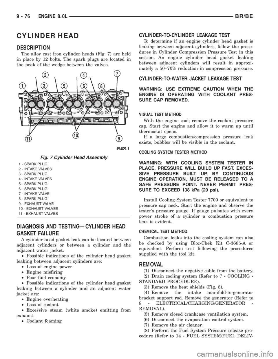
CYLINDER HEAD
DESCRIPTION
The alloy cast iron cylinder heads (Fig. 7) are held
in place by 12 bolts. The spark plugs are located in
the peak of the wedge between the valves.
DIAGNOSIS AND TESTINGÐCYLINDER HEAD
GASKET FAILURE
A cylinder head gasket leak can be located between
adjacent cylinders or between a cylinder and the
adjacent water jacket.
²Possible indications of the cylinder head gasket
leaking between adjacent cylinders are:
²Loss of engine power
²Engine misfiring
²Poor fuel economy
²Possible indications of the cylinder head gasket
leaking between a cylinder and an adjacent water
jacket are:
²Engine overheating
²Loss of coolant
²Excessive steam (white smoke) emitting from
exhaust
²Coolant foaming
CYLINDER-TO-CYLINDER LEAKAGE TEST
To determine if an engine cylinder head gasket is
leaking between adjacent cylinders, follow the proce-
dures in Cylinder Compression Pressure Test in this
section. An engine cylinder head gasket leaking
between adjacent cylinders will result in approxi-
mately a 50±70% reduction in compression pressure.
CYLINDER-TO-WATER JACKET LEAKAGE TEST
WARNING: USE EXTREME CAUTION WHEN THE
ENGINE IS OPERATING WITH COOLANT PRES-
SURE CAP REMOVED.
VISUAL TEST METHOD
With the engine cool, remove the coolant pressure
cap. Start the engine and allow it to warm up until
thermostat opens.
If a large combustion/compression pressure leak
exists, bubbles will be visible in the coolant.
COOLING SYSTEM TESTER METHOD
WARNING: WITH COOLING SYSTEM TESTER IN
PLACE, PRESSURE WILL BUILD UP FAST. EXCES-
SIVE PRESSURE BUILT UP, BY CONTINUOUS
ENGINE OPERATION, MUST BE RELEASED TO A
SAFE PRESSURE POINT. NEVER PERMIT PRES-
SURE TO EXCEED 138 kPa (20 psi).
Install Cooling System Tester 7700 or equivalent to
pressure cap neck. Start the engine and observe the
tester's pressure gauge. If gauge pulsates with every
power stroke of a cylinder a combustion pressure
leak is evident.
CHEMICAL TEST METHOD
Combustion leaks into the cooling system can also
be checked by using Bloc-Chek Kit C-3685-A or
equivalent. Perform test following the procedures
supplied with the tool kit.
REMOVAL
(1) Disconnect the negative cable from the battery.
(2) Drain cooling system (Refer to 7 - COOLING -
STANDARD PROCEDURE).
(3) Remove the heat shields (Fig. 8).
(4) Remove the intake manifold-to-generator
bracket support rod. Remove the generator (Refer to
8 - ELECTRICAL/CHARGING/GENERATOR -
REMOVAL).
(5) Remove closed crankcase ventilation system.
(6) Disconnect the evaporation control system.
(7) Remove the air cleaner.
(8) Perform the Fuel System Pressure release pro-
cedure (Refer to 14 - FUEL SYSTEM/FUEL DELIV-
Fig. 7 Cylinder Head Assembly
1 - SPARK PLUG
2 - INTAKE VALVES
3 - SPARK PLUG
4 - INTAKE VALVES
5 - SPARK PLUG
6 - SPARK PLUG
7 - INTAKE VALVE
8 - SPARK PLUG
9 - EXHAUST VALVE
10 - EXHAUST VALVES
11 - EXHAUST VALVES
9 - 76 ENGINE 8.0LBR/BE
Page 1169 of 2255
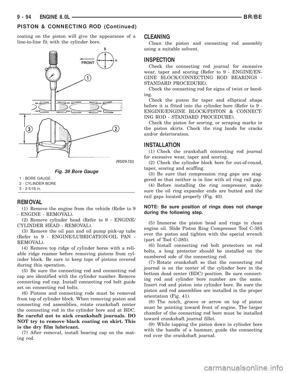
coating on the piston will give the appearance of a
line-to-line fit with the cylinder bore.
REMOVAL
(1) Remove the engine from the vehicle (Refer to 9
- ENGINE - REMOVAL).
(2) Remove cylinder head (Refer to 9 - ENGINE/
CYLINDER HEAD - REMOVAL).
(3) Remove the oil pan and oil pump pick-up tube
(Refer to 9 - ENGINE/LUBRICATION/OIL PAN -
REMOVAL).
(4) Remove top ridge of cylinder bores with a reli-
able ridge reamer before removing pistons from cyl-
inder block. Be sure to keep tops of pistons covered
during this operation.
(5) Be sure the connecting rod and connecting rod
cap are identified with the cylinder number. Remove
connecting rod cap. Install connecting rod bolt guide
set on connecting rod bolts.
(6) Pistons and connecting rods must be removed
from top of cylinder block. When removing piston and
connecting rod assemblies, rotate crankshaft center
the connecting rod in the cylinder bore and at BDC.
Be careful not to nick crankshaft journals. DO
NOT try to remove black coating on skirt. This
is the dry film lubricant.
(7) After removal, install bearing cap on the mat-
ing rod.
CLEANING
Clean the piston and connecting rod assembly
using a suitable solvent.
INSPECTION
Check the connecting rod journal for excessive
wear, taper and scoring (Refer to 9 - ENGINE/EN-
GINE BLOCK/CONNECTING ROD BEARINGS -
STANDARD PROCEDURE).
Check the connecting rod for signs of twist or bend-
ing.
Check the piston for taper and elliptical shape
before it is fitted into the cylinder bore (Refer to 9 -
ENGINE/ENGINE BLOCK/PISTON & CONNECT-
ING ROD - STANDARD PROCEDURE).
Check the piston for scoring, or scraping marks in
the piston skirts. Check the ring lands for cracks
and/or deterioration.
INSTALLATION
(1) Check the crankshaft connecting rod journal
for excessive wear, taper and scoring.
(2) Check the cylinder block bore for out-of-round,
taper, scoring and scuffing.
(3) Be sure that compression ring gaps are stag-
gered so that neither is in line with oil ring rail gap.
(4) Before installing the ring compressor, make
sure the oil ring expander ends are butted and the
rail gaps located properly (Fig. 40).
NOTE: Be sure position of rings does not change
during the following step.
(5) Immerse the piston head and rings in clean
engine oil. Slide Piston Ring Compressor Tool C-385
over the piston and tighten with the special wrench
(part of Tool C-385).
(6) Install connecting rod bolt protectors on rod
bolts, a long protector should be installed on the
numbered side of the connecting rod.
(7) Rotate crankshaft so that the connecting rod
journal is on the center of the cylinder bore in the
bottom dead center (BDC) position. Be sure connect-
ing rod and cylinder bore number are the same.
Insert rod and piston into cylinder bore. Be sure the
piston and rod assemblies are installed in the proper
orientation (Fig. 41).
(8) The notch, groove or arrow on top of piston
must be pointing toward front of engine. The larger
chamfer of the connecting rod bore must be installed
toward crankshaft journal fillet.
(9) While tapping the piston down in cylinder bore
with the handle of a hammer, guide the connecting
rod over the crankshaft journal.
Fig. 39 Bore Gauge
1 - BORE GAUGE
2 - CYLINDER BORE
3 - 2-5/16 in.
9 - 94 ENGINE 8.0LBR/BE
PISTON & CONNECTING ROD (Continued)
Page 1171 of 2255
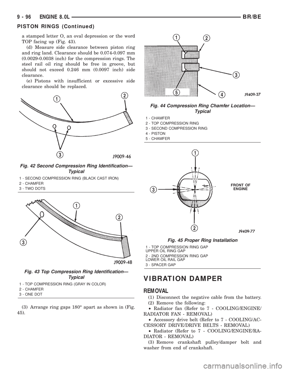
a stamped letter O, an oval depression or the word
TOP facing up (Fig. 43).
(d) Measure side clearance between piston ring
and ring land. Clearance should be 0.074-0.097 mm
(0.0029-0.0038 inch) for the compression rings. The
steel rail oil ring should be free in groove, but
should not exceed 0.246 mm (0.0097 inch) side
clearance.
(e) Pistons with insufficient or excessive side
clearance should be replaced.
(3) Arrange ring gaps 180É apart as shown in (Fig.
45).
VIBRATION DAMPER
REMOVAL
(1) Disconnect the negative cable from the battery.
(2) Remove the following:
²Radiator fan (Refer to 7 - COOLING/ENGINE/
RADIATOR FAN - REMOVAL)
²Accessory drive belt (Refer to 7 - COOLING/AC-
CESSORY DRIVE/DRIVE BELTS - REMOVAL)
²Radiator (Refer to 7 - COOLING/ENGINE/RA-
DIATOR - REMOVAL)
(3) Remove crankshaft pulley/damper bolt and
washer from end of crankshaft.
Fig. 42 Second Compression Ring IdentificationÐ
Typical
1 - SECOND COMPRESSION RING (BLACK CAST IRON)
2 - CHAMFER
3 - TWO DOTS
Fig. 43 Top Compression Ring IdentificationÐ
Typical
1 - TOP COMPRESSION RING (GRAY IN COLOR)
2 - CHAMFER
3 - ONE DOT
Fig. 44 Compression Ring Chamfer LocationÐ
Typical
1 - CHAMFER
2 - TOP COMPRESSION RING
3 - SECOND COMPRESSION RING
4 - PISTON
5 - CHAMFER
Fig. 45 Proper Ring Installation
1 - TOP COMPRESSION RING GAP
UPPER OIL RING GAP
2 - 2ND COMPRESSION RING GAP
LOWER OIL RAIL GAP
3 - SPACER GAP
9 - 96 ENGINE 8.0LBR/BE
PISTON RINGS (Continued)
Page 1192 of 2255
CONDITION POSSIBLE CAUSES CORRECTION
LUBRICATING OIL
PRESSURE TOO HIGH1. Pressure switch/gauge not
operating properly.1. Verify pressure switch is functioning
correctly. If not, replace switch/gauge.
2. Engine running to cold. 2. Refer to Coolant Temperature Below
Normal (Refer to 7 - COOLING -
DIAGNOSIS AND TESTING).
3. Oil viscosity too thick. 3. Make sure the correct oil is being used.
(Refer to LUBRICATION &
MAINTENANCE/FLUID TYPES -
DESCRIPTION).
4. Oil pressure relief valve stuck
closed or binding4. Check and replace valve.
LUBRICATING OIL LOSS 1. External leaks. 1. Visually inspect for oil leaks. Repair as
required.
2. Crankcase being overfilled. 2. Verify that the correct dipstick is being
used.
3. Incorrect oil specification or
viscosity.3. (a) Make sure the correct oil is being
used (Refer to LUBRICATION &
MAINTENANCE/FLUID TYPES -
DESCRIPTION).
(b) Look for reduced viscosity from dilution
with fuel.
(c) Review/reduce oil change intervals.
4. Oil cooler leak 4. Check and replace the oil cooler.
5. High blow-by forcing oil out the
breather.5. Check the breather tube area for signs of
oil loss. Perform the required repairs.
6. Turbocharger leaking oil to the air
intake.6. Inspect the air ducts for evidence of oil
transfer. Repair as required.
7. Piston rings not sealing (oil being
consumed by the engine).7. Perform blow-by check. Repair as
required.
COMPRESSION KNOCKS 1. Air in the fuel system. 1. Bleed the fuel system (Refer to 14 -
FUEL SYSTEM/FUEL DELIVERY -
STANDARD PROCEDURE).
2. Poor quality fuel or water/gasoline
contaminated fuel.2. Verify by operating from a temporary
tank with good fuel. Clean and flush the
fuel tank. Replace fuel/water separator filter.
3. Engine overloaded. 3. Verify the engine load rating is not being
exceeded.
4. Incorrect injection pump timing. 4. Check injection pump for proper
installation.
5. Improperly operating injectors. 5. Check and replace inoperative injectors.
EXCESSIVE VIBRATION 1. Loose or broken engine mounts. 1. Replace engine mounts.
2. Damaged fan or improperly
operating accessories.2. Check and replace the vibrating
components.
3. Improperly operating vibration
damper3. Inspect/replace vibration damper.
BR/BEENGINE 5.9L DIESEL 9 - 117
ENGINE 5.9L DIESEL (Continued)
Page 1202 of 2255
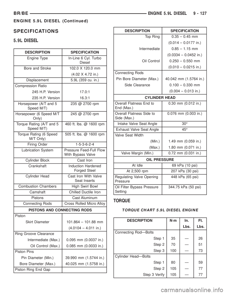
SPECIFICATIONS
5.9L DIESEL
DESCRIPTION SPECIFICATION
Engine Type In-Line 6 Cyl. Turbo
Diesel
Bore and Stroke 102.0 X 120.0 mm
(4.02 X 4.72 in.)
Displacement 5.9L (359 cu. in.)
Compression Ratio
245 H.P. Version 17.0:1
235 H.P. Version 16.3:1
Horsepower (A/T and 5
Speed M/T)235 @ 2700 rpm
Horsepower (6 Speed M/T
Only)245 @ 2700 rpm
Torque Rating (A/T and 5
Speed M/T)460 ft. lbs. @ 1600 rpm
Torque Rating (6 Speed
M/T Only)505 ft. lbs. @ 1600 rpm
Firing Order 1-5-3-6-2-4
Lubrication System Pressure Feed-Full Flow
With Bypass Valve
Cylinder Block Cast Iron
Crankshaft Induction Hardened
Forged Steel
Cylinder Head Cast Iron With Valve
Seat Inserts
Combustion Chambers High Swirl Bowl
Camshaft Chilled Ductile Iron
Pistons Cast Aluminum
Connecting Rods Cross Rolled Micro Alloy
PISTONS AND CONNECTING RODS
Piston
Skirt Diameter 101.864 ± 101.88 mm
(4.0104 ± 4.011 in.)
Ring Groove Clearance
Intermediate (Max.) 0.095 mm (0.0037 in.)
Oil Control (Max.) 0.085 mm (0.0033 in.)
Piston Pins
Pin Diameter (Min.) 39.990 mm (1.5744 in.)
Bore Diameter (Max.) 40.025 mm (1.5758 in.)
Piston Ring End Gap
DESCRIPTION SPECIFICATION
Top Ring 0.35 ± 0.45 mm
(0.014 ± 0.0177 in.)
Intermediate 0.85 ± 1.15 mm
(0.0334 ± 0.0452 in.)
Oil Control 0.250 ± 0.550 mm
(0.010 ± 0.0215 in.)
Connecting Rods
Pin Bore Diameter (Max.) 40.042 mm (1.5764 in.)
Side Clearance 0.100 ± 0.330 mm
(0.004 ± 0.013 in.)
CYLINDER HEAD
Overall Flatness End to
End (Max.)0.30 mm (0.012 in.)
Overall Flatness Side to
Side (Max.)0.076 mm (0.003 in.)
Intake Valve Seat Angle 30É
Exhaust Valve Seat Angle 45É
Valve Seat Width
(Min.) 1.49 mm (0.059 in.)
(Max.) 1.80 mm (0.071 in.)
Valve Margin (Min.) 0.72 mm (0.031 in.)
OIL PRESSURE
At Idle 69 kPa (10 psi)
At 2,500 rpm 207 kPa (30 psi)
Regulating Valve Opening
Pressure448 kPa (65 psi)
Oil Filter Bypass Pressure
Setting344.75 kPa (50 psi)
TORQUE
TORQUE CHART 5.9L DIESEL ENGINE
DESCRIPTION N´m In. Ft.
Lbs. Lbs.
Connecting RodÐBolts
Step 1 35 Ð 26
Step 2 70 Ð 51
Step 3 100 Ð 73
Cylinder HeadÐBolts
Step 1 80 Ð 59
Step 2 105 Ð 77
Step 3 Verify 105 Ð 77
BR/BEENGINE 5.9L DIESEL 9 - 127
ENGINE 5.9L DIESEL (Continued)
Page 1281 of 2255
(4) Connect the DRBIIItto the pressure trans-
ducer following the instructions supplied with the
DRB IIIt.
(5) Enter DRBIIItinto pressure reading mode and
test drive vehicle.
(6) The turbocharger boost pressure must be
between 110 - 138 kpa (16 - 20 psi.). If pressure read-
ings are lower than 110 kpa (16 psi.) inspect for the
following:
²Restricted air inlet system
²Leak in the charge air cooler system (Refer to 11
- EXHAUST SYSTEM/TURBOCHARGER SYSTEM/
CHARGE AIR COOLER AND PLUMBING - DIAG-
NOSIS AND TESTING)
²Turbocharger wastegate broken or misadjusted
²Turbocharger damaged (Refer to 11 - EXHAUST
SYSTEM/TURBOCHARGER SYSTEM/TURBO-
CHARGER - INSPECTION)
TURBOCHARGER
DESCRIPTION
The turbocharger is an exhaust-driven super-
charger which increases the pressure and density of
the air entering the engine. With the increase of air
entering the engine, more fuel can be injected into
the cylinders, which creates more power during com-
bustion.
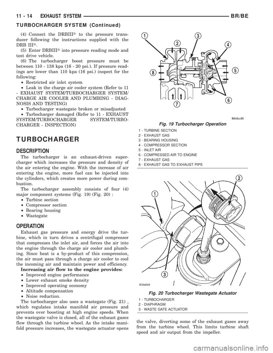
The turbocharger assembly consists of four (4)
major component systems (Fig. 19) (Fig. 20) :
²Turbine section
²Compressor section
²Bearing housing
²Wastegate
OPERATION
Exhaust gas pressure and energy drive the tur-
bine, which in turn drives a centrifugal compressor
that compresses the inlet air, and forces the air into
the engine through the charge air cooler and plumb-
ing. Since heat is a by-product of this compression,
the air must pass through a charge air cooler to cool
the incoming air and maintain power and efficiency.
Increasing air flow to the engine provides:
²Improved engine performance
²Lower exhaust smoke density
²Improved operating economy
²Altitude compensation
²Noise reduction.
The turbocharger also uses a wastegate (Fig. 21) ,
which regulates intake manifold air pressure and
prevents over boosting at high engine speeds. When
the wastegate valve is closed, all of the exhaust gases
flow through the turbine wheel. As the intake mani-
fold pressure increases, the wastegate actuator opensthe valve, diverting some of the exhaust gases away
from the turbine wheel. This limits turbine shaft
speed and air output from the impeller.
Fig. 19 Turbocharger Operation
1 - TURBINE SECTION
2 - EXHAUST GAS
3 - BEARING HOUSING
4 - COMPRESSOR SECTION
5 - INLET AIR
6 - COMPRESSED AIR TO ENGINE
7 - EXHAUST GAS
8 - EXHAUST GAS TO EXHAUST PIPE
Fig. 20 Turbocharger Wastegate Actuator
1 - TURBOCHARGER
2 - DIAPHRAGM
3 - WASTE GATE ACTUATOR
11 - 14 EXHAUST SYSTEMBR/BE
TURBOCHARGER SYSTEM (Continued)